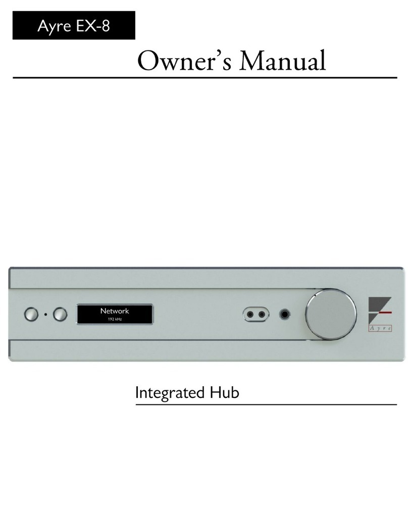
Ayre EX-8 User manual

Ayre EX-8
Owner’s Manual
Integrated Hub

2

3
Welcome to
Connection and
Controls and
Setup and
Streaming and
Numbers and
In Case
Statement o
A Place for
Ayre . . . . . . . . . . . . . . . . . . . . . . . . . . . . . . . . . . . . . 4
Installation . . . . . . . . . . . . . . . . . . . . . . . . . . . . . . . 6
Operation . . . . . . . . . . . . . . . . . . . . . . . . . . . . . . . .13
Customization . . . . . . . . . . . . . . . . . . . . . . . . . . . . 18
Networking. . . . . . . . . . . . . . . . . . . . . . . . . . . . . . .28
Specifications . . . . . . . . . . . . . . . . . . . . . . . . . . . . . 34
Trouble . . . . . . . . . . . . . . . . . . . . . . . . . . . . . . . . . 35
Warranty . . . . . . . . . . . . . . . . . . . . . . . . . . . . . . . . 39
Notes . . . . . . . . . . . . . . . . . . . . . . . . . . . . . . . . . . . 43
Contents
Welcome to
Setup and
Connection and
Controls and
Statement of
Streaming and
Numbers and
In Case of
A Place for
Table of

4
Thank you for purchasing the EX-8 Integrated Hub. We
sincerely hope you get as much joy listening through it as
we did designing and building it.
Our team has been designing world-class, award winning
products since 1993. It is our goal to make the most
musically accurate equipment we possibly can at any
given price range. We enjoy designing, building, and
talking about what we do. If you have any questions
about your new Ayre product, please don’t hesitate to
give us a call.
Your EX-8 is the culmination of decades of audio
innovation, distilling elements from Ayre’s most
celebrated works into one powerful piece of equipment.
As always, the warmth and immediacy of a live
performance are apparent from the first listening.
Combining superb resolution and a natural, relaxed
quality, your EX-8 will draw you into the music time
and time again.
This level of performance has been implemented using
the highest level of workmanship and materials. You can
be assured the EX-8 will provide you a lifetime of
musical enjoyment.
Welcome to
To our North American
customers, please be sure to
mail
your warranty
registration card.
Ayre

5
To begin enjoying your EX-8, connect any audio
source to the rear of the unit. You may also use a
wired or wireless Ethernet connection to begin
streaming music.
For the most current information on streaming
music with your EX-8, visit the streaming section
of our website: http://streaming.ayre.com
Connect your choice of an output device
(headphones, loudspeakers, or secondary amplifier) to
the appropriate connectors of the EX-8, and then
supply the EX-8 with power from a wall outlet.
Toggle the rear power switch to the ON (I) position
to provide power to the unit.
Press the left-hand button on the front of the EX-8 or
power button on the included remote control to wake
the unit from sleep. Use the right-hand button (on
the faceplate) or left and right arrow keys (on the
remote control) to select the input you wish to use.
Control the volume using either the knob on the EX-
8 or the + and – keys on the remote control.
Quick Start
The information required
to install, operate, and
optimize your amplifier is
contained in the following
three chapters of this
manual. The remaining
chapters cover
additional
information that may be
read at your leisure.

6
The Ayre EX-8 is easy to set up and use. The following
guidelines will ensure the installation goes smoothly.
At this point, you should consider how you would like
to use the EX-8 in your system and how to incorporate
your other equipment.
In this section, you will find descriptions of the various
connections that are available on your EX-8, as well as
recommendations for their intended use.
A good location for the EX-8 is in an open-backed
cabinet or on a shelf. The amplifier section produces a
moderate amount of heat during operation. Be sure to
provide at least three inches (75 mm) of air space
above the amplifier.
An adequate supply of air flow will avoid
overheating the amplifier.
The receiver for the remote control is between the two
front panel buttons. A line of sight from the listening
position will ensure maximum range.
Connection and
Do not stack the Ayre EX-8
directly with other
components,
as this may
restrict the air flow
or induce
hum into the audio
circuitry.
The infrared beam will travel
through glass.
Location
Installation

7
Due to the manufacturing processes used for the wires,
capacitors, and circuit board materials, a break-in
period is necessary for the amplifier to reach its full
sonic potential.
Each input uses a different physical path on the
input circuit board, therefore a separate break-
in period is required for each input.
Every EX-8 comes complete with three analog audio
inputs: one pair of balanced XLR inputs (B1)and
two pairs of single-ended RCA inputs (S1 and S2).
The Digital base option of the EX-8 includes four
inputs, one AES balanced input (AES/EBU), one RCA
(S/PDIF), and two TOSLINK (Optical 1 and 2).
The USB option includes one USB type B port for
asynchronous USB audio (USB Audio Input).
The Network option allows you to connect to your
local area network (Ethernet Input). There are also two
USB ports (USB Host)which allow you to connect
wirelessly using the included USB Wi-Fi adapter
and/or directly access files from a USB flash drive.
Once installed, a break-in
period of around 100 to 500
hours will allow the amplifier to
reach its full sonic potential.
Analog Inputs
Digital Inputs
Break-in Period
When you have a choice, a
balanced connection will offer
slightly higher sound quality
than a single-ended connection.
The digital inputs on the EX-8
are options which can be
included when the product is
first ordered or can be added at
a later time.

8
1) Loudspeaker Outputs
2) USB Host Ports
3) Ethernet Input
4) Word Clock Output
5) AES/EBU Input
6) S/PDIF Input
7) Optical Inputs
8) AyreLink Ports
9) Firmware Update Port
10) USB Audio Input
11) Balanced Analog Input
12) Singled-ended Analog Inputs
13) Preamp/Sub Outputs
14) On/Off Power Switch
15) Preamp/Sub Output Mode Switch
16) AC Fuse holder
17) IEC Power inlet
USB Audio Input
Fi rm ware
Update
AyreLink
AyreLink
Volts
50/60 Hertz
500 WMax
Preamp/Sub Outputs Analog Inputs
B1
S1S2
Preamp/Sub
Output Mode
Stereo
Mono
B1
S1 S2
Analog Inputs Preamp/Sub Outputs
EX-8 Integrated Hub
Serial No.
Optical Inputs
1 2
USB Ho st US B Host
Ethernet
Input Word Clk
Output
AES/EBU
Input
S/PDIF Input
Boulder, Colorado USA
A y r e
1 2
3
2
1
4
5
6
7
8
9
10
11
12
13
15
14
16
17
13
12
11

9
1
3
2
4
5
6
7
1) Left-hand Button
•Sleep/Mute
2) IR Receiver / Status LED
3) Right-hand Button
•Input Select
4) Display
5) Balanced Headphone Out
6) Single-ended Headphone Out
7) Volume Control

10
Stereo
Mono
1 2
The EX-8 drives the loudspeakers with balanced outputs.
Since none of the output terminals are grounded,
connecting any of them to ground may result in damage
to the amplifier.
Do not connect the loudspeaker outputs to
any speaker switch-box, accessory, or test
equipment that has a common ground
connection.
The balanced and single-ended preamplifier outputs on
the rear panel of the EX-8 allow for a seperate
amplifier/subwoofer to be driven. Two switches
accessible through the rear panel allow for these outputs
to be configured as mono or stereo. Both switches must
be in the same position (up or down) for the outputs to
operate as intended.
Headphones can be connected easily to the front of the
EX-8. Between the display and volume knob you will
find three connectors; one for single-ended headphones
and two for a set of balanced headphones. The single ¼”
on the right will allow you to listen in single-ended
mode.
Loudspeaker Outputs
Headphone Outputs
Preamplifier Outputs
The heavy-
duty output
terminals of the Ayre EX-
8
work best with speaker cables
equipped with ¼” spade lugs.
The Stereo/Mono Selection
switch lets you configure your
preamplifier outputs for
different purposes.
¼” Headphone Jack:
Single-ended

11
The two 3.5mm connectors on the left will allow you to
listen to headphones in balanced mode. These outputs
are not compatible with single-ended headphones.
Headphones with a 3.5mm stereo connector can
be used with the EX-8 by using a ¼” to 3.5mm
adapter.
Only use headphones with stereo phone plugs
(two insulating rings). Mono phone plugs
(single ring) may damage the unit. Four
conductor (three rings) plugs may not
connect properly, distorting the sound.
The EX-8 automatically detects when headphones are
plugged in. The loudspeaker and preamp outputs are
disabled while the headphone outputs are active.
All outputs on the EX-8 share a common
volume control. Exercise caution when
connecting headphones, as ‘nominal’ volume
levels vary.
The AyreLink communication system provides a
convenient way to control your audio system. There are
two AyreLink ports on the rear panel of the EX-8. Each
port has four contacts and contains both an input and an
output. Both ports function identically and may be used
interchangeably.
Be sure to use two-line telephone cords to
make AyreLink connections. These can be
identified by the four gold contacts on each
connector.
AyreLink Ports
For improved stack
integration, try connecting
your Ayre equipment
together with AyreLink.
3.5mm Headphone Jacks:
Balanced

12
The linked components should be connected in daisy-
chain fashion, connecting each component to another
until all of the linked components have been connected.
Be careful not to connect the two ends of the chain.
Closing the chain to form a loop will cause the AyreLink
system not to function.
Some digital products have word clock inputs and
provide higher performance when supplied with a high-
quality external word clock. The word clock output in
the Ayre EX-8 is derived from the ultra-low phase-noise
master clock built into the Digital base option.
The Firmware Update port allows you to update core
Firmware with a USB flash drive. For more
information, see page 25.
Word Clock Output
The word clock output lets
yo
u synchronize a digital
source to the EX-8.
Firmware Update Port
To use AyreLink with an
integrated control system, an
optional RS-
232 adapter box
is available.
Contact your
Ayre dealer for details.

13
System-sleep mode reduces
the power consumption of
the EX-8 without turning it
off completely.
Operation
Active mode provides
power to the audio circuit
and enables the system for
listening.
The following chapter details operation of the EX-8. On
the front of the unit, you will find two buttons, a status
LED, a display, an IR receiver for the remote, and a
volume knob. In addition to these controls, some
network applications can provide further integration
with the unit.
When first turned on, the EX-8 automatically enters
System-sleep mode, indicated by a green status LED.
The amplifier’s audio circuitry is disabled, reducing the
amount of power it draws. To activate the unit, simply
press the left-hand button on the front of the unit, or the
power button on the remote. If either button is held for
three seconds, AyreLink connected devices will also be
turned on.
Once in Active mode, the audio circuitry in the unit is
enabled. The currently selected input is displayed on the
screen and any signal present at that input will be driven
to the enabled output(s). When available, information or
meta-data from a digital recording being played will be
shown on the EX-8’s display.
System-sleep Mode
Active Mode
Controls and

14
Volume Control
The volume control in the EX-8 is motorized and may
be controlled using the knob on the front of the unit, the
remote control handset, or a network application.
Input Selection
By pressing the right-hand button on the front panel,
the currently selected input will cycle to the next enabled
input. This may also be adjusted using the left/right
arrow keys or number keys on the remote handset. To
learn more about enabling/disabling inputs, see page 21.
Mute / System-sleep
A quick press of the left-hand button will mute the
audio outputs of the EX-8. While muted, an icon will
appear on the display. A second short press of the left-
hand button will un-mute the unit.
By pressing and holding the left-hand button for three
seconds, the EX-8 and any AyreLink connected devices
will return to System-sleep mode.
Headphones
When either single-ended or balanced headphones are
connected, the amplifier automatically reconfigures for
headphone playback, and the headphone symbol is
shown on the display.
By pressing the headphone button on the remote
control, you can switch between headphone and rear-
panel outputs while headphones are connected.
The EX-
8 volume control is
purely analog.
To make input selection
easier, try disabling any
inputs you aren’t using
through the menu.
When muted, the amplifier
prevents signal from
reaching the outputs.

15
Brightness button
Display
After a period of inactivity the display automatically
powers off, indicated by a blue status LED. This
minimizes the amount of active digital circuitry to
ensure the best sound quality while also extending the
lifetime of the display. This feature may be extended,
shortened, or disabled entirely through the menu, see
page 23.
The brightness of the display may be controlled via
remote control. Each press of the brightness button
cycles through the four available brightness settings.
Changing the brightness on your EX-8 will adjust
the display brightness of any AyreLink connected
components to the same level.
Sample Rate
When digital audio is playing, the EX-8 will display the
sample rate it is receiving. If you are expecting a different
sample rate than what the EX-8 shows, check the
settings in your source software.
Meta-data
If “Track” or “Artist” information becomes available
while using the Network input, it will be displayed on
the screen.
The display in the EX-
8 is
rated for years of use, but to
keep it in best condition we
recommend that
the display
be allowed to timeout.

16
HDCD Indicators
If Pacific Microsonics HDCD headers are detected in
the digital data-stream, the HDCD icon will appear on
the screen to indicate the EX-8 is playing true HDCD.
Pre-emphasis Indicator
The letters PRE beside the sample rate indicates that the
current track was recorded with pre-emphasis, and the
proper de-emphasis EQ is being applied.

17
123
456
78 9
0
OK
The provided remote control handset will operate the
Ayre EX-8 as well as other Ayre products.
The top row of buttons contains illuminating product
selection keys. By pressing one of these, you may select
which type of device you would like to control.
Whenever another button is pressed, the key
corresponding to the current selection will illuminate.
1) Product Selection Keys
2) System-sleep / Active Mode
3) Brightness Cycle
4) Mute Toggle
5) Number Keys (Input Selection)
6) Headphone button
7) Navigation keys
a. Up (Volume)
b. Down (Volume)
c. Left (Previous Input)
d. Right (Next Input)
e. Enter Setup
f. OK (Select)
g. Return
8) Transport Controls (Not used)
Remote Handset
3
1
2
4
5
7
8
c
b
a
d
e
g
f
6

18
Setup button
Return button
Your EX-8 offers a high level of flexibility in terms of
setup. The following information will allow you to
configure the unit in the best way for your system.
To access and operate the menu, you may either use the
remote included with the unit, or the two buttons to the
left of the display.
Operation using the remote
To access the menu, press the Setup button on the
remote. “Setup Menu” will be displayed on the screen
briefly, then the main menu will load. All outputs are
muted while the unit is in the setup menu.
Once in the menu, the navigation keys (up, down, left
and right) allow you to adjust your selection in the
menu. With the desired selection highlighted, press OK
to select it. To return to the previous screen, press the
Return button. To immediately exit the menu, you may
press the Setup button at any time.
Customization
Setup and
Setup Menu

19
Arrow symbols indicate more
content is available off-screen:
Setting Selection marker:
Operation using front panel buttons
To access the menu, you must first place the unit into
System-sleep mode. This can be done by pressing and
holding the left-hand button for 3 seconds and will be
indicated by a green status LED. Next press and hold the
right-hand button for three seconds. “Setup Menu” will
be displayed on the screen briefly, then the root menu
will load.
Once in the menu, the right-hand button will allow you
to adjust your current selection; each press will cycle
through the list of available options. With the desired
selection highlighted, a quick press of the left-hand
button will select it. To return to the previous screen,
press and hold the left-hand button.
Screen layout and icons
The menu screen is organized with the section title at the
top and a list of options below.
At any one time, four options may be displayed on the
screen. An arrow symbol on either the left or right side
of the screen indicates that more options are available
off-screen, in that direction.
Some screens contain a list of sub-menus, while others
control a specific setting. On a setting screen, the current
value of the setting being modified is indicated by a
mark to the left of that setting. Once a new setting has
been selected, the mark moves to reflect the change.

20
From the main menu, you will have access to the five
main sub-menus: Input, Output, Display, Network, and
System.
The Input sub-menu will allow you to access settings
specific to each input installed in your EX-8.
The Output sub-menu contains settings for the output
sections of your amplifier.
The Display sub-menu will allow you to adjust the
display timeout setting, which causes the display to turn
off after a preset period of inactivity.
The Network sub-menu will allow you to access Wi-Fi
setup functions, network connection information,
network F/W updates, and network module reset.
The System sub-menu will allow you to set Auto-sleep
mode, check current F/W revisions, check module
installation, and perform a system factory default reset.
After entering the Input sub-menu, select the input you
would like to modify. The settings available for the
selected input will appear.
Some settings are available for all inputs, while others are
only available for analog or digital inputs exclusively.
Menu Structure and Contents
Input Sub-menu
The EX-
8 setup menu has
five sub-
menus, which allow
you to optimize the
amplifier
for your system.
Different settings are
available for the different
types of
inputs available in
the EX-8.
Other manuals for EX-8
2
Table of contents
Other Ayre Switch manuals
Popular Switch manuals by other brands

Intelligent network solutions
Intelligent network solutions TSM100-K quick start guide

Leonton
Leonton PG2-1002-10GSFP Series user manual

CTM LYNG
CTM LYNG 5648533 Installation and user instructions

SOtM
SOtM tX-USBhubEX operating instructions

Planet Networking & Communication
Planet Networking & Communication SGS-5220 user manual

HP
HP 316095-B21 - StorageWorks Edge Switch 2/24 installation instructions