BDI 8/16 Product manual

Broadcast Devices, Inc.
8/16 Passive
Switcher
TECHNICAL REFERENCE MANUAL
Broadcast Devices, Inc.
www.broadcast-devices.com
Tel. (914) 737-5032
Fax. (914) 736-6916 REV: D01/21

Table of Contents
I. Introduction 3
II.
Specifications
3
III. Installation 4-5
IV.
Warranty
6
V. Schematic Diagrams 7-9

I. Introduction
The 8/16 Switcher series are an 8 or 16 input, 2 by 1 passive switchers. The 8/16 series are
capable of accepting up to two or four sets of balanced inputs and switching them to a single or
dual set of up to 8 outputs. The signal path is completely passive using latching relays. Front
panel and remote control of the unit is possible. Local status is provided by lights on the front
panel and remote status is provided via dry contact closure on the remote control connector. The
unit requires only a momentary connection to ground on the appropriate pin for switcher
operation.
A. Unpacking and Inspection
Carefully unpack the unit after receipt and inspect for damage that may have occurred during
shipping. If damage is noted, contact the shipper immediately and file a damage claim. The
contents of the package have been insured to cover total replacement cost. Make certain that the
package contents are the same as noted on the packing slip. If not, contact Broadcast Devices,
Inc. Check to make sure all mechanical parts are secure.
B. General Description
The 8/16 series switchers can accept as many as two sets of 8 or 16 monaural balanced inputs
which can be selected to a single or dual set of 8 outputs. By use of a simple microprocessor unit
the control functions of the unit can be made to be momentary or maintained closure for
command. In addition there is provision for configuring the unit for power loss position memory or
not. The signal path is completely passive.
The front panel has two momentary lighted pushbutton switches. They provide local control and
status of the 8/16 Switcher.
II. Specifications
Input Connectors: DB25 Female
Output Connector: DB25
Female
Remote Control Connector: DB25 Female
Status: Dry
Contact NC/C/NO for position
Number of A/B inputs: 8 balanced for 8 Channel unit 16 for 16 channel unit
Power Requirements: 100 - 240 Volts A.C. 50 - 60 Hertz
Operating Temperature Range: 0 - 60° Celsius non condensing atmosphere
Physical Dimensions: 1.75 H X 19 W X 10 D (inches)
Shipping Weight: 14 lbs.

III. Installation
A. Initial Configuration
The unit as configured from the factory is set to accept 100 to 240 Volts A.C. 50 - 60 Hertz
electrical power. No changes are necessary to change voltage selection.
B. Location and Hookup Considerations
Locate the 8/16 in a 19-inch E.I.A. standard rack enclosure in close proximity to the equipment
that it is going to interface between. Allow sufficient airflow space between equipment to allow for
proper cooling. Make all desired input and output connections to your external equipment using
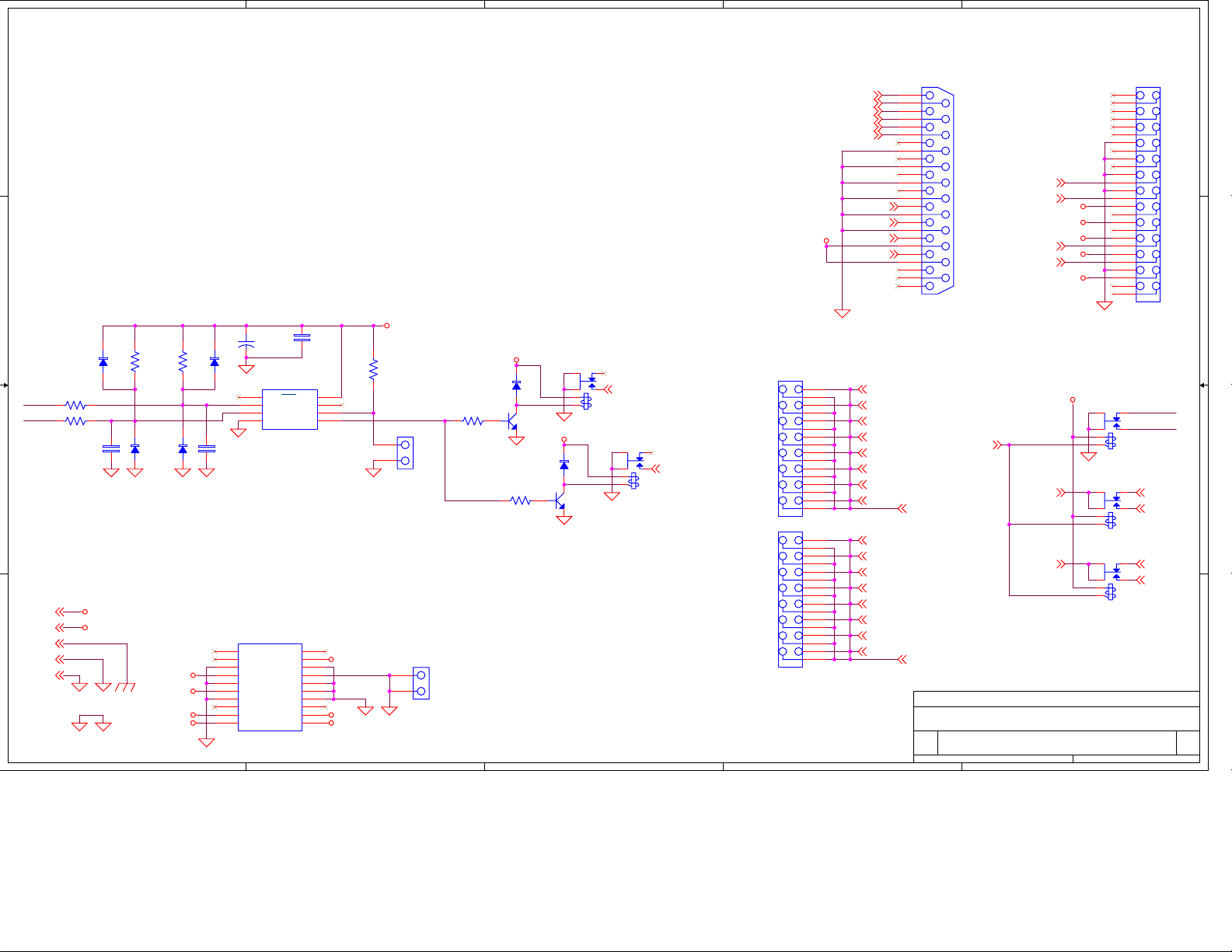
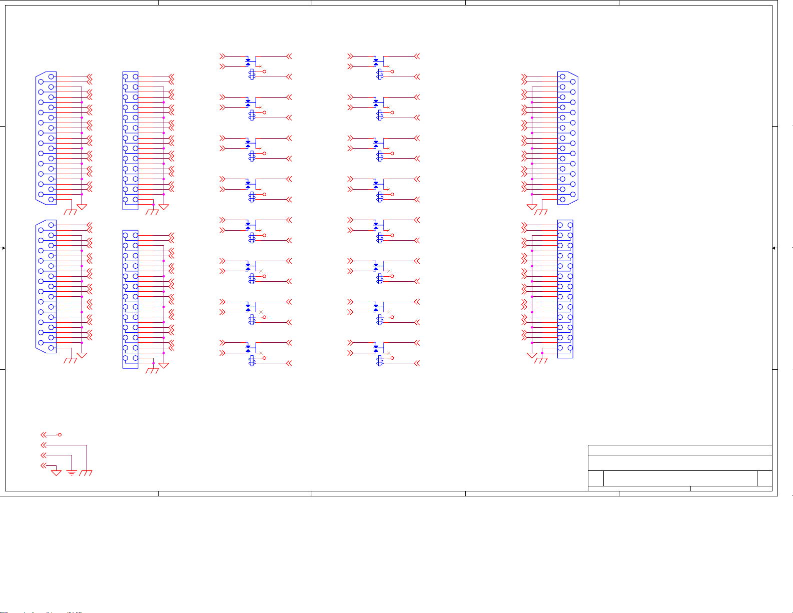
the pin out provided for the DB25 connectors. Optional DB25 to XLR breakout panels are
available from bdi. The audio connector pin assignments which can be found in the schematics
section of this manual conform to the Tascam A-DAT™ format. This is a commonly used
worldwide standard for which cable assemblies are available from multiple sources including BDI.
Call us for more information about availability and pricing.
Always make sure that the 8/16 is plugged in to a properly grounded A.C. receptacle. A common
practice to break ground loops is to isolate the chassis from electrical ground. THIS IS NOT
RECOMMENDED AND WILL VOID THE WARRANTY IF DONE IN THE FIELD. An alternate
method to break ground loops is to break the signal grounds on one side of the equipment.
C. Remote Control/Status Connection
Refer to the table on the following page for remote control and status connections. The 8/16
requires a momentary ground closure for switching operation in its factory default mode. The 8/16
can accept an open collector output for this purpose or a simple relay closure will actuate a
switching function. Status provided is a set of dry contacts offering NO/C/NC connection to
remote control equipment.
D. Optional User Features
i. Maintained Switch Closure Operation Instructions:
The 8/16 Switcher can be configured to require a maintained remote closure to hold the B
position. In this configuration a maintained remote control closure is necessary to keep the
switcher in the B position. To place the 8/16 in this mode connect pin 8 of J2 Remote
Control/Status connector to common such as pin 17. To command the 8/16 into the B position
connect a switch closure from J2 Remote Control/Status connector pin 9 to common such as pin
18. As long as the connection between pin 9 and to any of the common pins 17-20 the unit will
remain in the B position. To command to the A position the connection between pin 9 and
common is broken.
ii. Power Loss Memory
When the 8/16 is configured for momentary closure to command from A to B or B to A input
(factory default), the 8/16 can be configured to default to the last channel selected upon power up
or can be configured to default to the A position upon power up. Factory default is for the 8/16 to
remember last channel selected upon power up. If it is desired for the unit to always default to
position A upon power up remove the top cover and locate JP3 on the main PC board. The
jumper should be installed connecting the two pins together. Check the operation of the unit after
installing the jumper and then replace the top cover.

IV. Warranty
Broadcast Devices, Inc. products are warranted against failure due to faulty materials or
workmanship for a period of one year from the date of shipment to the ultimate user. The
warranty covers repair or replacement of defective parts at the factory, provided the unit has been
returned prepaid by the user. All shipments to the factory shall have affixed to the outside of the
container an R. A. number obtained from the factory. The above warranty is void if the unit has
been modified by the user outside of any recommendations from the factory or if the unit has
been abused or operated outside of its electrical or environmental specifications. If customer
conducted field tests suggest that the unit may be faulty, whether or not the unit is in warranty, a
full report of the difficulty should be sent to Broadcast Devices, Inc. factory. The office may
suggest further tests or authorize return for factory evaluation. Units sent to the factory should be
well packed and shipped to Broadcast Devices, Inc. – Check our web site for shipping address at
www.broadcast-devices.com Remember to affix the R.A. number to the outside of the
carton. Any packages received without such R.A. number will be refused. Note: freight collect
shipments will also be refused. When the unit has been received, inspected and tested, the
customer will receive a report of the findings along with a quotation for recommended repairs,
which are found falling outside of the standard warranty. Units returned for in-warranty repairs
which are found not to be defective will be subject to an evaluation and handling charge. In
warranty units will be repaired at no charge and returned via prepaid freight.
Out-of-warranty units needing repair require a purchase order and will be invoiced for parts,
labor, and shipping charges. When ordering replacement part, always specify A) Part number or
Description, and Quantity; B) Date of Purchase, Where Purchased; C) Any Special Shipping
Instructions. Always specify a street address, as shipping companies cannot deliver to a postal
box.
Broadcast Devices, Inc. is not responsible for any other manufacturer’s warranty on original
equipment. Nor are we responsible for any failure, damage, or loss of property that may occur
due to the installation or operation of our equipment outside of recommended specifications.
Broadcast Devices, Inc. reserves the right to make changes to specifications and materials
without prior notice.

V. Schematic Diagrams
A. Schematic Diagrams

5
5
4
4
3
3
2
2
1
1
D D
C C
B B
A A
Broadcast Devices, Inc.
REMOTE DB-25
PWR SUPPLY
BUTTON
BOARD
C
8/16 SWITCHER CONTROL
B
13Monday, July 22, 2013
{}
Title
Size Document Number Rev
Date: Sheet of
STATUSA
STATUSB
POSA
POSB RELAYS
+12V
+5V
AGND
DGND
EARTH
RELAY8
RELAY5
RELAY6
RELAY3
RELAY7
RELAY4
RELAY2
RELAY1
RELAY15
RELAY12
RELAY14
RELAY11
RELAY13
RELAY16
RELAY9
RELAY10
POSB
STATUSA
POSA
STATUSB
K36-NC
K37-NO
K37-COM
K36-COM
K36-NO
K37-NC
ALL-RELAYS
ALL-RELAYS
ALL-RELAYS
ALL-RELAYS
ALL-RELAYS
K37-COM
K36-NO
K37-NC
K37-NO
K36-NC
K36-COM
POSB
STATUSB
STATUSA
POSA
+12V
+5V
D
+5V
+12V
D
+5V
D
D
D
+5V
+5V
+5V
+5V
+5V
D
+5V
D
+5V
D
D
+5V
-12V
D
+5V
DD D
D
+5V LOGIC
+5V LOGIC
D
D
D
D
+5V
+5V
D
Q5
2N3904
K35
CIT J1031C5VDC.15S
P9
DB25
1
14
2
15
3
4
5
6
7
8
9
10
11
12
13
16
17
18
19
20
21
22
23
24
25
U4
ATTINY13A
1
2
3
4 5
6
7
8
PB5/RST
PB3
PB4
GND PB0
PB1
PB2
VCC
JP1
HDR8X2
1
2
3
4
5
6
7
8
9
10
11
12
13
14
15
16
+
C4
100uF 6.3V
JP2
HDR8X2
1
2
3
4
5
6
7
8
9
10
11
12
13
14
15
16
CR5
1N4148
C3
.1 50V
R9
220 1/4W
CR1
1N4148
K38
CIT J1031C5VDC.15S
P10
HDR26
1
2
3
4
5
6
7
8
9
10
11
12
13
14
15
16
17
18
19
20
21
22
23
24
25
26
Q6
2N3904
J3
39-30-0200
1
2
3
4
5
6
7
8
9
10 20
19
18
17
16
15
14
13
12
11
+3.3V
+3.3V
COM
+5V
COM
+5V
COM
PW-OK
+5VSB
+12V +5V
+5V
N/C
COM
COM
COM
PS-ON
COM
-12V
+3.3V
J4
HDR2
1
2
K37
CIT J1031C5VDC.15S
CR6
1N4148
CR3
1N4148
K34
CIT J1031C5VDC.15S
R6
4.70K 1/4W
R8
4.70K 1/4W
C2
.1 50V
R7
4.70K 1/4W
JP3
PWR UP MODE
1
2
R12
4.70K 1/4W
R10
220 1/4W
C1
.1 50V
CR4
1N4148
CR2
1N4148
R11
4.70K 1/4W
K36
CIT J1031C5VDC.15S

5
5
4
4
3
3
2
2
1
1
D D
C C
B B
A A
Broadcast Devices, Inc.
C
8/16 SWITCHER CHAN 1-8
B
23Monday, July 22, 2013
{}
Title
Size Document Number Rev
Date: Sheet of
+5V
AGND
DGND
EARTH
CH5AN
CH6AP
CH1AN
CH8AP
CH2AP
CH3AP
CH4AN
CH1AP
CH7AP
CH2AN
CH3AN
CH7AN
CH4AP
CH5AP
CH8AN
CH6AN
CH1BP
CH5BP
CH7BN
CH7BP
CH8BP
CH5BN
CH3BP
CH4BP
CH2BP
CH3BN
CH6BP
CH6BN
CH8BN
CH2BN
CH4BN
CH1BN
CH1-OUTP
CH5-OUTP
CH7-OUTN
CH7-OUTP
CH8-OUTP
CH5-OUTN
CH3-OUTP
CH4-OUTP
CH2-OUTP
CH3-OUTN
CH6-OUTP
CH6-OUTN
CH8-OUTN
CH2-OUTN
CH4-OUTN
CH1-OUTN
CH1AP
CH1BP
CH1-OUTP CH1-OUTN
CH1BN
CH1AN
CH5AP CH5AN
CH3AP
CH4AP
CH2AP
CH3AN
CH6AP CH6AN
CH2AN
CH4AN
CH2BP
CH8BP CH8BN
CH3BP CH3BN
CH7BP
CH4BP
CH5BP
CH7BN
CH4BN
CH2BN
CH6BN
CH5BN
CH8AP CH8AN
CH7AP CH7AN
CH6BP
CH7-OUTN
CH4-OUTN
CH2-OUTP
CH7-OUTP
CH3-OUTN
CH8-OUTN
CH5-OUTN
CH2-OUTN
CH8-OUTP
CH5-OUTP
CH3-OUTP
CH4-OUTP
CH6-OUTNCH6-OUTP
RELAY1 RELAY1
RELAY2
RELAY3
RELAY4
RELAY5
RELAY6
RELAY7
RELAY8
RELAY5
RELAY3
RELAY4
RELAY7
RELAY6
RELAY8
RELAY2
CH5AP
CH1AN
CH3AN
CH2AP
CH7AP
CH6AN
CH4AN
CH5AN
CH4AP
CH8AN
CH6AP
CH1AP
CH3AP
CH2AN
CH8AP
CH7AN
CH6BN
CH5BN
CH7BN
CH3BN
CH7BP
CH1BN
CH6BP
CH8BP
CH2BP
CH5BP
CH3BP
CH1BP
CH4BN
CH4BP
CH8BN
CH2BN
CH1-OUTN
CH2-OUTN
CH6-OUTN
CH5-OUTP
CH4-OUTP
CH3-OUTN
CH4-OUTN
CH3-OUTP
CH1-OUTP
CH8-OUTP
CH7-OUTP
CH2-OUTP
CH8-OUTN
CH7-OUTN
CH5-OUTN
CH6-OUTP
+5V
+5V
+5V
+5V
+5V
+5V
+5V
+5V +5V
+5V +5V
+5V +5V
+5V +5V
+5V +5V
P3
DB25
1
14
2
15
3
4
5
6
7
8
9
10
11
12
13
16
17
18
19
20
21
22
23
24
25
K8
CIT J1031C5VDC.15S
K5
CIT J1031C5VDC.15S
K2
CIT J1031C5VDC.15S
K17
CIT J1031C5VDC.15S
P3A
HDR26
1
2
3
4
5
6
7
8
9
10
11
12
13
14
15
16
17
18
19
20
21
22
23
24
25
26
K16
CIT J1031C5VDC.15S
K11
CIT J1031C5VDC.15S
K10
CIT J1031C5VDC.15S
K6
CIT J1031C5VDC.15S
K3
CIT J1031C5VDC.15S
K7
CIT J1031C5VDC.15S
P4
DB25
1
14
2
15
3
4
5
6
7
8
9
10
11
12
13
16
17
18
19
20
21
22
23
24
25
K15
CIT J1031C5VDC.15S
P4A
HDR26
1
2
3
4
5
6
7
8
9
10
11
12
13
14
15
16
17
18
19
20
21
22
23
24
25
26
P5A
HDR26
1
2
3
4
5
6
7
8
9
10
11
12
13
14
15
16
17
18
19
20
21
22
23
24
25
26
K14
CIT J1031C5VDC.15S
K13
CIT J1031C5VDC.15S
K9
CIT J1031C5VDC.15S
P5
DB25
1
14
2
15
3
4
5
6
7
8
9
10
11
12
13
16
17
18
19
20
21
22
23
24
25
K12
CIT J1031C5VDC.15S
K4
CIT J1031C5VDC.15S

5
5
4
4
3
3
2
2
1
1
D D
C C
B B
A A
Broadcast Devices, Inc.
C
8/16 SWITCHER CHAN 9-16
B
33Monday, July 22, 2013
{}
Title
Size Document Number Rev
Date: Sheet of
+5V
AGND
DGND
EARTH
CH13AN
CH14AP
CH9AN
CH16AP
CH10AP
CH11AP
CH12AN
CH9AP
CH15AP
CH10AN
CH11AN
CH15AN
CH12AP
CH13AP
CH16AN
CH14AN
CH9-OUTP
CH13-OUTP
CH15-OUTN
CH15-OUTP
CH16-OUTP
CH13-OUTN
CH11-OUTP
CH12-OUTP
CH10-OUTP
CH14-OUTP
CH14-OUTN
CH16-OUTN
CH10-OUTN
CH12-OUTN
CH9-OUTN
RELAY9
RELAY10
RELAY11
RELAY12
RELAY13
RELAY14
RELAY15
CH14BN
CH15BN
CH9BP
CH12BP
CH12BN
CH11BN
CH14BP
CH10BP
CH13BN
CH16BN
CH15BP
CH16BP
CH13BP
CH9BN
CH10BN
CH11BP
CH11-OUTN
RELAY16
RELAY9
RELAY10
RELAY12
RELAY15
RELAY11
RELAY13
RELAY14
RELAY16
CH14AN
CH15AN
CH9AP
CH12AP CH12AN
CH11AN
CH14AP
CH10AP
CH13AN
CH16AN
CH15AP
CH16AP
CH13AP
CH9AN
CH10AN
CH11AP
CH12BP
CH13BP
CH15BP
CH9BP
CH11BP
CH14BP
CH16BP
CH10BP CH10BN
CH12BN
CH9BN
CH16BN
CH11BN
CH13BN
CH15BN
CH14BN
CH10-OUTN
CH16-OUTP
CH13-OUTP
CH11-OUTP
CH14-OUTN
CH15-OUTP
CH12-OUTP
CH14-OUTP
CH9-OUTP
CH10-OUTP
CH16-OUTN
CH9-OUTN
CH12-OUTN
CH15-OUTN
CH13-OUTN
CH11-OUTN
+5V
+5V
+5V
+5V
+5V
+5V
+5V
+5V +5V
+5V +5V
+5V +5V
+5V +5V
+5V +5V
K27
CIT J1031C5VDC.15S
K22
CIT J1031C5VDC.15S
K23
CIT J1031C5VDC.15S
K31
CIT J1031C5VDC.15S
K30
CIT J1031C5VDC.15S
K29
CIT J1031C5VDC.15S
K25
CIT J1031C5VDC.15S
K28
CIT J1031C5VDC.15S
K20
CIT J1031C5VDC.15S
K24
CIT J1031C5VDC.15S
K21
CIT J1031C5VDC.15S
K18
CIT J1031C5VDC.15S
P8
HDR26
1
2
3
4
5
6
7
8
9
10
11
12
13
14
15
16
17
18
19
20
21
22
23
24
25
26
K33
CIT J1031C5VDC.15S
K32
CIT J1031C5VDC.15S
K26
CIT J1031C5VDC.15S
P7
HDR26
1
2
3
4
5
6
7
8
9
10
11
12
13
14
15
16
17
18
19
20
21
22
23
24
25
26
P6
HDR26
1
2
3
4
5
6
7
8
9
10
11
12
13
14
15
16
17
18
19
20
21
22
23
24
25
26
K19
CIT J1031C5VDC.15S
Table of contents
Other BDI Switch manuals
Popular Switch manuals by other brands

H3C
H3C S3100-52P installation manual

Siemens
Siemens 3LD3.10 Series operating instructions

Brocade Communications Systems
Brocade Communications Systems A7533A - Brocade 4Gb SAN Switch Base Command reference

IOGear
IOGear MicroHub GUH274W3 Manual do usuário

Analog way
Analog way Smart Vu LE user manual

Lindy
Lindy 32586 quick start guide

Panasonic
Panasonic AV(FS-FS-T) manual

TP-Link
TP-Link TL-SG1005P installation guide

HB Products
HB Products HBSR instruction manual

ZyXEL Communications
ZyXEL Communications GS2220 Series user guide

Nortel
Nortel Application Switch 2424-SSL Product brief

HP
HP aruba 9300-32D Series Installation and getting started guide