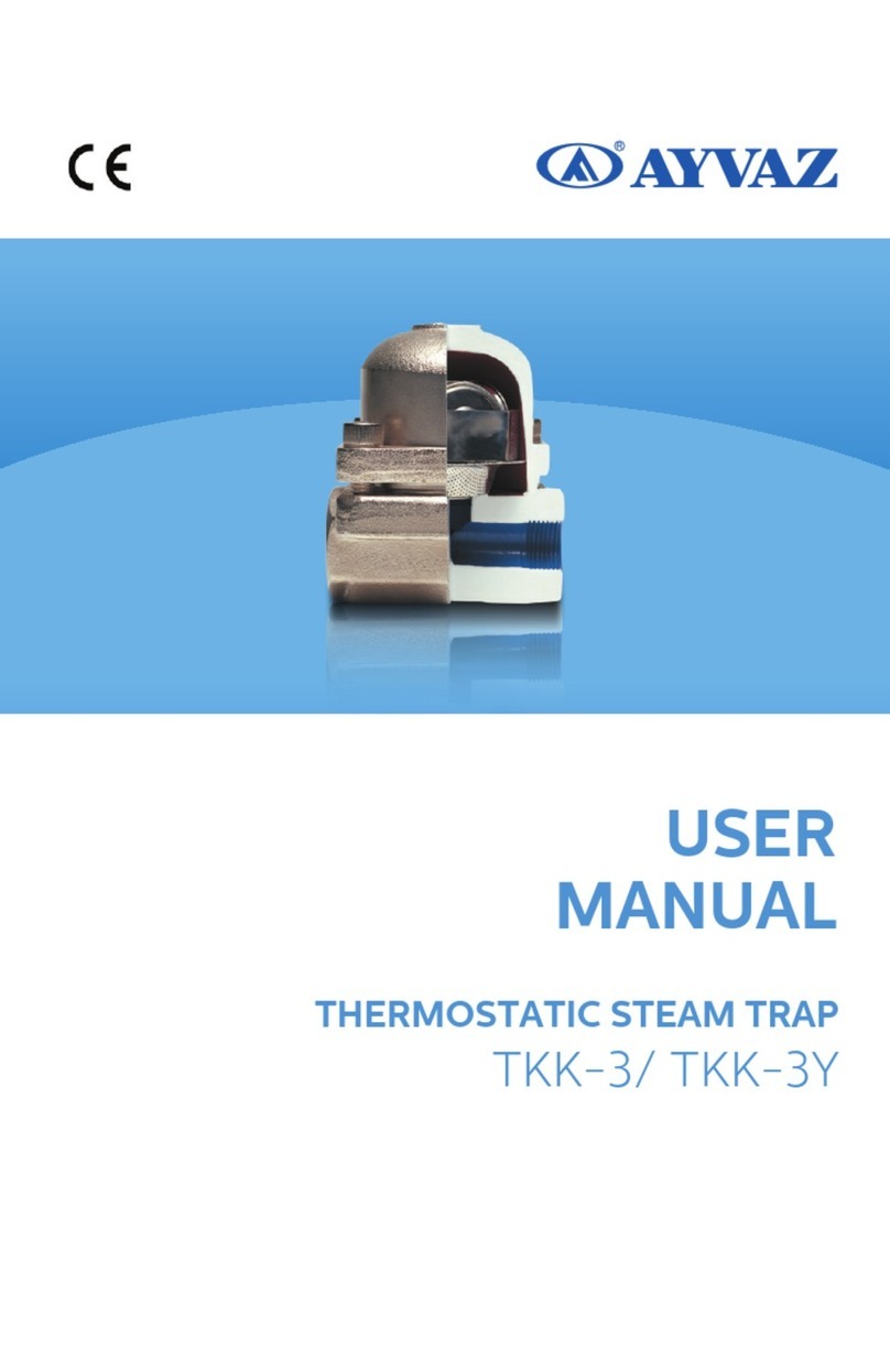
AYVAZ TK-1 User manual

BIMETALLIC STEAM TRAP
TK-1/ TK-1A
USER
MANUAL

© 03/2019 Hacı Ayvaz Endüstriyel Mamuller Sanayi ve Ticaret A.Ş.
All Rights Reserved.
AYVAZ® is a registered trademark.
Please read this manual before you start using it!
SYMBOLS AND DESCRIPTIONS
Warning Signs in User's Guide
MPORTANT INFORMATION
DANGER
FIRE DANGER Warning danger of fire!
HOT SURFACE Warning risk of hot surface!
HIGH VOLTAGE
Shows useful tips and suggestions.
Indicates danger to life and property.
Warning danger of electric shock!
Bimetallic Steam Trap

Bimetallic Steam Trap
CONTENT
General Information
General Features
Safety and Environmental Instructions
Transport, Packaging and Storage
Installation
Operation
Maintenance and Cleaning Disassembly,
Maintenance and Cut-out
Technical Drawing
2
2
PAGE TITLE
3-4
4
5
5
6
7
8-9

2
Bimetallic Steam Trap
Product Code: TK-1 / TK-1A
2. GENERAL FEATURES
2.1 GENERAL SAFETY INFORMATION
The safety use of steam trap according to working instructions can be done if it
can be installed and maintained by qualified person. lnstallation of steam trap to
the line, safety instructions, safety tools and correct use of tools must be available
toó.
PRESSURE
Before the maintenance,be careful if there is pressure at the pipeline which the
steam trap is installed. lf there is a pressure in the system, it should be discharged
safety.
TEMPERATURE
Before the maintenance,be careful for the temperatura of steam trap. lt can cause
sorne physical injures. Please wait unlil the temperature is nominal.
·Products are designed and manufactured by professional persons. All parts are
manufactured with high quality standards and environmental factors in mind.
·The user manual describes the correct and safe use of the device. All health
and safety instructions must be followed during the installation.
·The operating area must be selected correctly to prevent accidents.
· That user manual is a part of the product and must be kept. If the product is
replaced, it must be returned with the user manual.
·The installer must carry out the installation in accordance with the warnings and
information specified in the user manual.
· General terms and conditions stated at sales document.
· Ayvaz reserves the right to change products, specifications at any time and
without any prior notice.
1. GENERAL INFORMATION

3
TK-1 Bimetallic steam trap is the combination of thermostatic and thermodynamic
steam trap. The opening and closing is provided with bi-metal plates. Valve design
is like check valve. It can be mounted horizontally, vertically, and at an angle,
paying attention to the flow direction. Housing cover is made of forged steel and
stainless steel.
3. SAFETY AND ENVIRONMENTAL INS.
This product is produced for commercial use. It is dangerous for household use.
3.1 General Safety Instructions
3.2 Working Conditions
Pressure Class PN40
PMA-Pressure Maximum Allowable (bar) 40
TMA-Temperature Maximum Allowable (°C) 400
PMO-Pressure Maximum Operating (bar) 32
TMO-Temperature Maximum Operating (°C) 250
PMX-Maximum Pressure Difference (bar) 32
Bimetallic Steam Trap
·Follow the installation and maintenance instructions of the user manual.
·Wear protective goggles and gloves during operation.
· Repairs should only be carried out by technical experts. Otherwise, accidents
may occur.
·Do not use non-operating switches and electronic devices. Contact the
authorized service for support.
·Signs should be placed where the fluid temperature is 60 ° C and above.
The device must be operated in accordance with the general safety instructions
listed above. Ayvaz cannot be held responsible for problems arising from use that
does not comply with the safety instructions.
3.3 Incorrect Usage
Incorrect use may result in hazardous situations and injuries.
· Do not make any changes to the product without authorization. Otherwise the
product will not be covered by the warranty.
· Do not use the product in hazardous areas.
Ayvaz cannot be held responsible for any dangerous situations and injuries caused
by incorrect usage.
Do not use this device in combination with safety precautions or emergency
devices.

4
Bimetallic Steam Trap
3.4 Responsibility of the User
This device is a commercial product. Therefore, the user is responsible for legal
obligations related to occupational safety.
Along with the safety instructions specified in this user manual; accident
prevention measures and environmental protection laws must be observed.
To use the device safely, the user must follow the instructions below;
·The user must be regularly familiar with occupational health and safety issues, be
familiar with first aid and be able to follow the instructions in this manual.
·User must read user manual and safety instructions and understand.
·Do not test the device and do not go beyond the instructions for use.
·Control of the safety, pressure and temperature of the facility where the device
will be used belongs to the user.
3.5 User Competence
Operating and handling errors can cause serious damage to the user and the
product.
·Actions described in this guide, a user with professional qualifications which is
mentioned below can perform operations.
Competent User
A competent user is an individual authorized by the company, who is able to
understand the technical information contained in this manual, has knowledge of
measurement and control, knows the legal responsibilities of the country in which
he performs the operation or installation operation, is able to operate
independently in dangerous areas, in compliance with current standards and
regulations.
3.6 Personal protective equipment
Personal protective equipment is a means of protecting competent users from
hazards that may occur during operation. The competent user must wear personal
protective equipment during installation.Follow the protection directives at the work
site.Personal protective equipment must be supplied by the company that
purchased the product.
4. TRANSPORT, PACKAGING AND STORAGE
4.1 Transport
After the device reaches you, check for damage caused by the transport. Report any
significant damage immediately.
4.2 Packaging and Storage
Do not remove the package before installing the device. Keep the device in a safe
place for damage.

5
5. INSTALLATION
Before the installation, you should read safety instructions carefully.
6. OPERATION
The main element in bimetallic steam traps is the valve and bimetallic itself.
bimetal; It is a composite material consisting of two separate plates having
different coefficients of expansion.
OPENING
When the system is cold, the valve is open and non-condensing gases and
cold condensate are discharged. When the system is activated, the metallic
plates that shrink by the cooling of the condensate from the condensate
provide the discharge of the condensate by pushing the valve from the bed.
CLOSING
When the hot condensate arrives, the long protrusions and then the short ones
are respectively bent, since the amount of bending at different temperatures is
proportional to the length of the protrusions. Therefore, they gradually pull the
valve towards its seat. As the temperature increases, the applied force increases
and stabilizes the bearing. As it is understood from the working principle, it keeps
the condensate in the steam chamber and waits for the temperature to drop
below a few degrees. This feature should be considered in practice.
STEAM LINE
STEAM LINE
FUEL-OIL LINE
FLOW DIRECTION
CONDENSATE LINE
DRAIN
FRONT VIEW
TK-1
SIDE VIEW
FUEL-OIL
LINE
S
T
E
A
M
L
I
N
E
Bimetallic Steam Trap
a- Check the label and technical information sheet if the product is suitable
for the required installation.
b- Check the maximum pressure and temperatura values. lf the pressure in the
system is higher than the maximum value of the product, provide the use of
safety tools in arder to preven! the excess pressure.
c- Indicate the flow direction and correct installation position. (The flow
directions is on the body.
d- Take off the covers from the product.
e- Consider the temperature of the released condense as 1 00ºC if there is
discharge of condense into atmosphere. Be sure that the system is working
correctly after the installation and maintenance.

6
7. MAINTENANCE AND CLEANING
7.1 Maintenance
Before doing any operation on the trap, such as; the condensate must be
isolated from the supply line and return line and the pressure in the system
must be relieved safely.
The trap should then be allowed to cool. When reassembling the system, all
connection surfaces must be clean.
7.2 Cleaning
It can cause physical injury, product damage and environmental damage.
The fluid in the device can be a risk to the user, the environment and the device
itself.
Bimetallic Steam Trap
· If there is a closing valve, first the bottom and then the top closing valve is closed.
The fluid inside the device is discharged into a suitable storage container through
the drain plug or valve.
·The device is carefully disassembled.
·The inside of the device is cleaned with a soft brush and the outside with a wet
cloth and left to dry.
·Electrical connections should not contact to wet area.
It can cause product damage and environmental damage.
·Do not clean with sharp or hard objects.
Discharge Capacities
Differential
Pressure P= Inlet Pressure
- Outlet Pressure
Discharge
Capacities
Red Chart
p = Condansate Discharge at
the temperature which is max 10°
C lower than steam saturation
temperature.
Blue Chart
p = Cold Condansate
Discharge at the temperature
which is 20°C

7
Bimetallic Steam Trap
8. DISASSEMBLY, MAINTENANCE AND CUT-OUT
Fluid that can cause physical injury, product damage and environmental damage.
·Carefully clean the dismantled device to eliminate physical injuries, fluid damage,
and damage to the environment.
8.1 Disassembly
If there are closing valves, remove the device safely after closing the closing valves.
If there is not closing valve, remove only the device to be disassembled on the
tank when the system pressure and electrical connections are cut off.
8.2 Maintenance
Clean the device carefully to eliminate physical injuries, product damage, and
environmental damage from the fluid before sending it to maintenance. Contact
our customer representative for shipping operations.
8.3 Cut-Out
This product is made of high quality parts and materials which are recyclable and
reusable. Therefore, do not dispose of the product with household or other waste
at the end of its service life.
Metal recycling facilities can be taken to recyling.
9.TECHNICAL DRAWING
DN(mm) H L
15 114,5 95
20 114,5 95
25 114,5 95
L
H

PART LIST
No Part Name Material
1 Body C 22,8
2 Control Unit Seat AISI 304
3 Gasket Klingerit
4 Seat AISI 304
5 Filter AISI 304
6 Seat Gasket AISI 304
7 Bolt 8,8
8 Bimetallic Plate Stem AISI 304
9 Cover C 22,8
10 Cover Set Gasket AISI 304
11 Cover Set Stopper 9 SMn 36
12 Gasket Rove AISI 304
13 Set Bolt Cushion AISI 304
14 Bimetallic Plate AISI 304
15 Bimetallic Plate AISI 304
16 Bimetallic Plate Part AISI 304
17 Threaded Reduction 9 SMn 36
DN(mm) H L
32 115,5 175
40 121 185
50 125,5 195,5
L
H
Bimetallic Steam Trap

DN(mm) H L
15 114,5 150
20 114,5 150
25 114,5 160
32 115,5 175
40 121 185
50 125,5 195
L
H
PART LIST
No Part Name Material
1 Body C 22,8
2 Control Unit Seat AISI 304
3 Gasket Klingerit
4 Seat AISI 304
5 Filter AISI 304
6 Seat Gasket AISI 304
7 Bolt 8,8
8 Bimetallic Plate Stem AISI 304
9 Cover C 22,8
10 Cover Set Gasket AISI 304
11 Cover Set Stopper 9 SMn 36
12 Gasket Rove AISI 304
13 Set Bolt Cushion AISI 304
14 Bimetallic Plate AISI 304
15 Bimetallic Plate AISI 304
16 Bimetallic Plate Part AISI 304
17 Flange C 22,8
18 Adapter C 1030
Bimetallic Steam Trap

DN(mm) H L
15 114,5 95
20 114,5 95
25 114,5 95
PART LIST
No Part Name Material
1 Body C 22,8
2 Control Unit Seat AISI 304
3 Gasket Klingerit
4 Seat AISI 304
5 Filter AISI 304
6 Seat Gasket AISI 304
7 Bolt 8,8
8 Bimetallic Plate Stem AISI 304
9 Cover C 22,8
10 Cover Set Gasket AISI 304
11 Cover Set Stopper 9 SMn 36
12 Gasket Rove AISI 304
13 Set Bolt Cushion AISI 304
14 Bimetallic Plate AISI 304
15 Bimetallic Plate AISI 304
16 Bimetallic Plate Part AISI 304
L
H
Bimetallic Steam Trap

PART LIST
No Part Name Material
1 Body C 22,8
2 Gasket Klingerit
3 Seat AISI 304
4 Filter AISI 304
5 Seat Gasket AISI 304
6 Imbus Bolt 8,8
7 Bimetallic Plate Stem AISI 304
8 Bolt Ring AISI 304
9 Adjustment Nut Bearing AISI 304
10 Bimetallic Plate AISI 304
11 Bimetallic Plate AISI 304
12 Bimetallic Plate AISI 304
13 Cover & Seat Welding Connection
14 Stem & Flap Welding Connection AISI 304
15 Adjustment Bolt AISI 304
16 O-ring Viton
17 Bolt Ring
18 Ring 1.0482
19 Nut
20 Gasket AISI 304
21 Adjustment Handle 1.0482
Bimetallic Steam Trap

8
Montage and Dismantling
a. Remove the cover clamps
b. Clean the strainer. Loosen the regulator.
c. The regulator is one piece. No need to disassemble to clean.
d. Clean the housing, clean the cover, clean the regulator, clean the gasket
seating surfaces and remove the gasket.
e. to Install a new cover gasket, replace the cover and tighten the bolts evenly.
KONTROL
ONAY
FİRMA RESİM NO:
AĞIRLIK:
MALZEME
ADET
RESİM NO:
YAYIN NO: 3
AYVAZ
R
İSİM
TARİH
İMZA
ÇİZEN
ÖLÇEK
>0.5
<3
>3
<6 >6
<30
>30
<120
>120
<400
±0.1
±0.2
±0.3
±0.1
±0.5
AYVAZ
R
>2000
<4000
GENEL TOLERANS DIN 7168 ORTA
B.ÖZBURSALI
D.YÜRÜSÜN
AYVAZ-CAD / Resim Üzerinden Ölçü Almayınız.
22.12.2009
E.LAK
1:1
TK1 FLANŞLI DN25 PN40
>400
<1000
>1000
<2000
±0.8
±1.2
±2
S.NO
ADET
PARÇA ADI
MALZEME
ÖLÇÜ
RESİM NO
AÇIKLAMA
1
2
3
1
1
1
Conta
Kontrol ünitesi supabı
Gövde
C 22,8
AISI 304
Kilingerit
603001000319
603404000000
214010303060
703.400.102.002
4
1
Sid
AISI 304
603404000001
S.NO
ADET
PARÇA ADI
MALZEME
ÖLÇÜ
RESİM NO
AÇIKLAMA
5
6
7
8
9
10
11
12
13
14
15
16
1
Süzgeç
AISI 304
603003000000
1
Sid contası
AISI 304
603003000005
4
İmbus civata
8.8
207020101256
2
Bimetal plaka mili
AISI 304
603408000000
1
Kapak ayar tapa contası
AISI 304
603407000000
1
Kapak
C 22.8
603402000000
1
Kapak ayar tapası
9 SMn 36
603408000006
1
Civata kilidi
AISI 304
603408000005
1
Ayar civata yatağı
AISI 304
603408000004
6
Bimetal plaka
AISI 304
603408000003
6
Bimetal plaka
AISI 304
603408000002
5
Bimetal plaka ara parçası
AISI 304
603408000001
17
2
Flanş
C 22.8
603107000008
DN25 / PN40
22.12.2009
PART LIST
No Part Name Material
1Body C 22,8
2Control Unit Seat AISI 304
3Gasket Kilingerit
4Seat AISI 304
5Filter AISI 304
6Seat Gasket AISI 304
7Imbus Bolt 8,8
8Bimetallic Plate Stem AISI 304
9Cover C 22,8
10 Cover Adjust Bolt AISI 304
11 Adjust Bolt Cover 9 SMn 36
12 Bolt Lock AISI 304
13 Adjust Seat AISI 304
14 Bimetallic Plate AISI 304
15 Bimetallic Plate AISI 304
16 Bimetallic Plate Gasket AISI 304
17 Flange C 22,8
18 Adapter C 1030
IMPORTANT
The thermal energy of the steam line is utilized to prevent heat loss in
the fuel-oil line. This prevents heat loss in the fuel-oil line.
In these lines, a bimetallic trap is used because of its working principle.
To benefit from the energy of the steam, bimetallic plates should be used
to open at the lowest point of the saturated steam temperature.
Bimetallic Steam Trap

11. ADJUSTMENT TK-1 A
1. Wear heat protection gloves for your own safety.
2. Remove the stem cover with tool.
3. Adjust the discharge temperature stem with screwdriver.
4. Close the stem cover.
HEAD OFFICE - FACTORY
Atatürk Sanayi Bölgesi Hadımköy Mahallesi
Mustafa İnan Caddesi No: 44 Arnavutköy - İSTANBUL
Tel: +90 212 771 01 45 (pbx) | Fax: +90 212 771 47 27
[email protected] | www.ayvaz.com
This manual suits for next models
1
Table of contents
Other AYVAZ Plumbing Product manuals
Popular Plumbing Product manuals by other brands

Tylo
Tylo Prime+ 1811 user manual

Hans Grohe
Hans Grohe Aquno Select M81 170 3jet sBox 73831 Series Instructions for use/assembly instructions

Axel
Axel ARAX.8105CR quick start guide

fine fixtures
fine fixtures VANNES VA1616 installation instructions

T&S
T&S 002824-40 Installation and maintenance instructions

Brizo
Brizo HK32 Series quick start guide

Sanela
Sanela SLS 02TB Instructions for use

Grohe
Grohe 34 211 manual

Hans Grohe
Hans Grohe AXOR Starck 10101 1 Series Installation/User Instructions/Warranty

Moen
Moen Show House S932 Specifications

Westfalia
Westfalia 81 29 64 instruction manual

NRS Healthcare
NRS Healthcare Linton Plus M53564 User instructions