Aztro DAVID G4 Setup guide

1
DAVID LABEL APPLICATOR
G4

2
DAVID LABEL APPLICATOR
INDEX
Chapter 1 Machine Overview
1.1 Overview
1.2 Specifications
1.3 Sequence of Events
Chapter 2 How to Set Up the Machine
2.1 Label Head Wind
2.2 Label Head Thread Pattern
2.3 Component Description and Operation
2.4 Label Head Button Operations
Chapter 3 Electrical/Pneumatic Diagrams
3.1 AC Wiring
3.2 Servo Wiring
Chapter 4 Parts
5.1 Machine Parts list and Suppliers List
5.2 Recommended Spares List
Chapter 5 Standards
5.1 List of Australian Standards Applicable to the Machine
Chapter 6 Maintenance
7.1 Maintenance Schedule
7.2 Trouble Shooting Guide
Chapter 7 Risk Assessments
7.1 Conveyor Risk Assessment
7.2 Label Head Risk assessment
7.3 Orientation Unit Risk Assessment
7.4 Electrical Cabinet Risk Assessment
7.5 Turn Table Risk Assessment

3
DAVID LABEL APPLICATOR
CHAPTER 1 MACHINE OVERVIEW
1.1 OVERVIEW
The David Label Applicator applies self adhesive labels to flat sided parallel products
that require a flat sided or round application. The David machine may consist of the
following:
•1 Right Hand stepper driven Label Head –To apply labels from the right-hand
side of the machine.
•Main Conveyor –To transport the product.
•Orientation Drive roller - To rotate and apply labels to round products with up to
100% wrap of the label.
•Capture Unit –To capture the product for labelling.
•Turn Table –To collect the product (Optional)
1.2 SPECIFICATIONS
Power Supply –10Amp 240Vac
Air supply –6 Bar
100.00 mm
A
z
t
ro
Label Copy 4
A
z
t
ro
1000.00 mm
455.00 mm
310.00 mm

4
1.3 SEQUENCE OF EVENTS
The sequence of events for David Labelling Application:
1. Product to be labelled enters the machine on the in-feed section of the main
conveyor.
2. Product travels along the conveyor triggering the product sensor.
3. The product sensor sends a signal to start the sequence of events. The capture
cylinder is activated at the completion of the start delay, turning on the capture
solenoid extending the capture cylinder. This in turn captures the product to be
labelled.
4. After the extend piston delay times out, the label head dispenses a label onto the
product.
5. The label gap sensor detects that the label has been ejected and stops the labels
feeding out.
6. After the retract delay has timed out, the capture solenoid is turned off and the
product is released.
7. The product continues the conveyor to be collected.
8. The sequence may now start again.

5
CHAPTER 2 HOW TO SET UP THE MACHINE
2.1 COMPONENT DESCRIPTION AND OPERATION
LABEL HEAD WIND
Up/Down Wind –By winding the Up/Down wind handle, the label head can be raised
and lowered to set the correct position of the peel plate to the surface that is being
labelled. Rotating the Up/Down handle Clockwise to raise to raise the label head up
higher on the product and rotate the Up/Down handle Counter Clockwise to lower the
label head lower on the product.
Figure 1
Up/Down

6
2.2 LABEL HEAD THREAD PATTERNS
The label web threading pattern of the label roll is most important to ensure the correct
label tension on the label web as it feeds through the machine. Some label head thread
patterns may vary, but the FIGURES below are the standard David Labelling Machine.
The label head thread pattern may be seen on the HMI screen by pressing the AZTRO
logo.
Fig 2

7
2.3 LABELLER COMPONENTS
LABEL HEAD
The label head function is to dispense labels on to the products. The components of a
standard label head are shown below:
Fig 3
Label Disk –The label disk assembly holds the roll of labels that are being used on the
labelling machine. Label rolls are pressed onto the label reel core to be held firmly into
position by the reel core blade. This stainless-steel blade can be bent to suit the cardboard
core of the labels to hold the core from slipping around the label reel core. The blade
needs to be engaging the label core with enough pressure to hold the core from slipping
while still allowing for easy core removal.
Fig 4
Label Disk
Dancer Arm
Peel Plate
Product sensor
Pinch Assembly
Label Gap Sensor
Guide Rollers
Waste Spool
REEL CORE BLADE

8
Dancer Arm –The Dancer Arm has the role of tensioning the labels and braking the
label disk to prevent the label roll from over running. The Dancer Assembly is a double
roller system to take some load of the label head motor when the labeler is operating at
higher speeds.
Fig 5
Brake O-ring - On the base of the label disk is a brake O-ring, this O-ring acts as friction
device for the dancer arm to engage. This O-ring needs regular checking for wear and
needs to be replaced if the rubber is cracked or worn to flat.
Fig. 6
Dancer arm tension - To tension the dancer, arm a tensioning knob is provided. There
are two locking grub screws on the dancer arm knob located 90 degrees to each other. If
these grub screws are loosened with an allen key the spring will uncoil slightly releasing
the tension. By twisting the knurled knob with your hand in the direction the spring is
coiled, the tension can be set. Hold the knob in the desired position whilst the grub
screws are tightened, locking the knob into position.
Fig. 7
BRAKE O’RING
DANCER ARM
TENSION KNOB

9
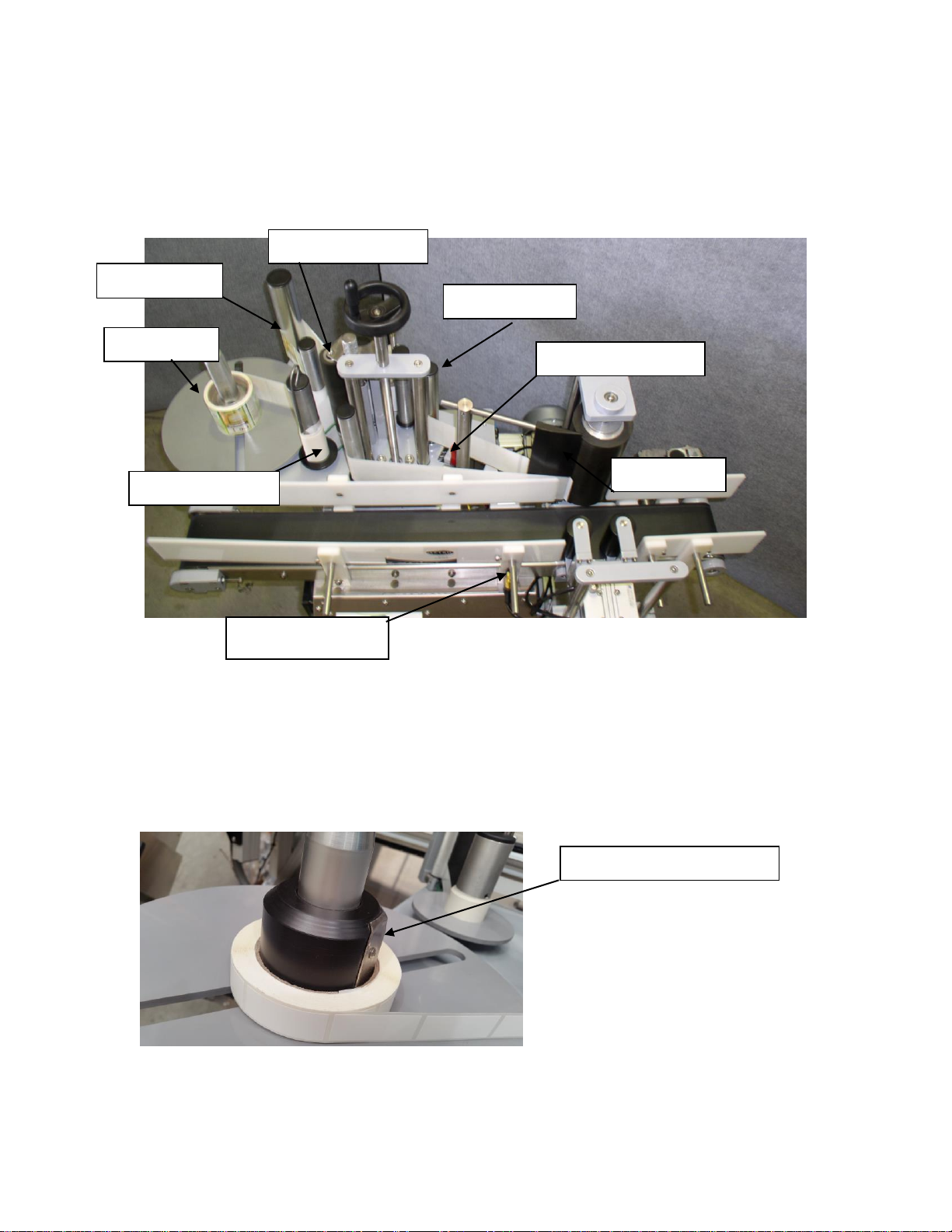
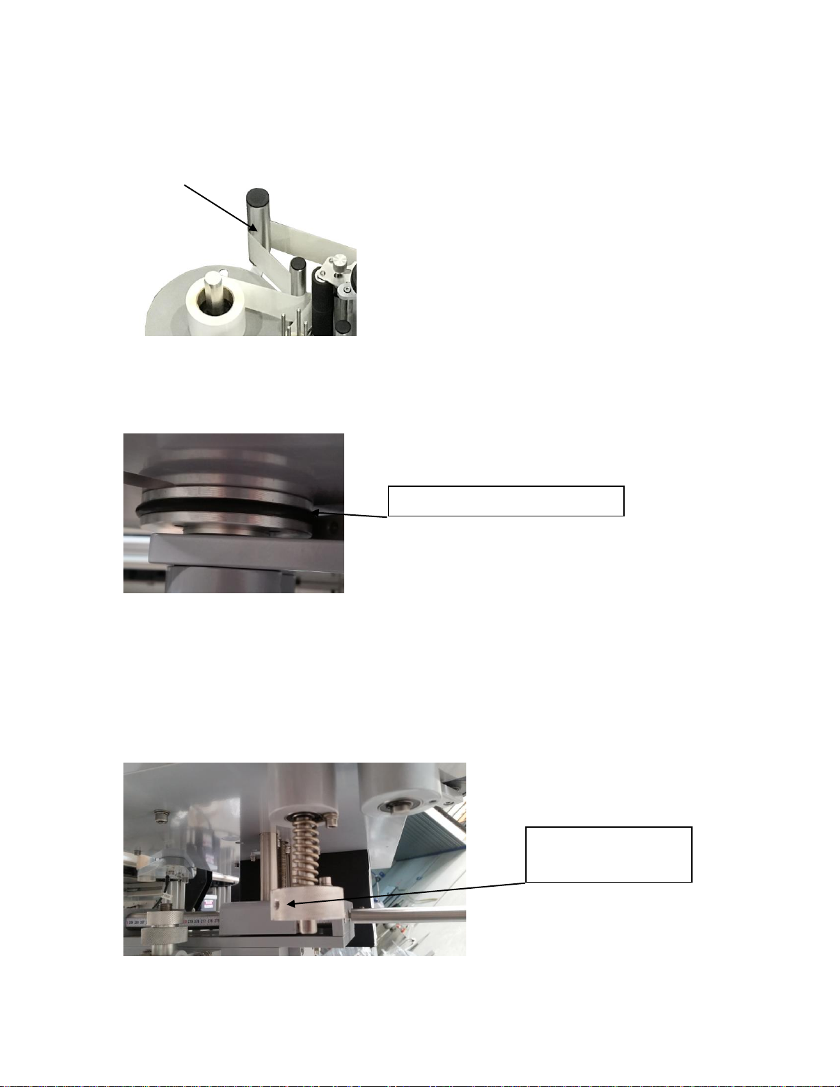
Guide Rollers –The guide rollers direct the path of the label movement around the label
head, it is very important that the correct path is threaded around the guide rollers to gain
the correct operation of the labeller. Label rings are fitted to the guide rollers to aid in the
tracking of the label head to give the operator a path to thread the label back at the correct
height. The label rings can be adjusted by sliding the up or down the roller.
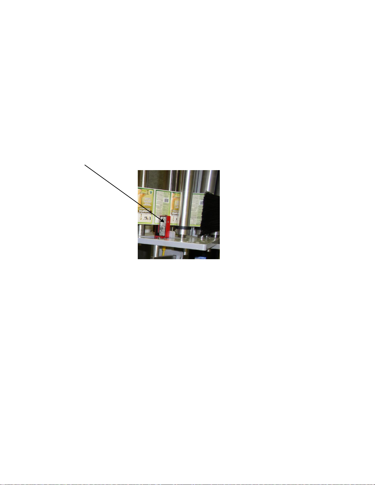
Label Gap Sensor –The Label Gap Sensor’s purpose is to end a labelling cycle. The
Label Gap Sensor is a fork sensor that has a beam of light that shines from an emitter to a
collector across the sensor. This beam of light is adjustable to control the sensitivity. The
sensitivity must be set to allow the sensor to only trigger when the label backing paper is
in the sensors eye. The sensor must not trigger on any part of the label. When the sensor
is triggered it sends a signal to the PLC (Programmable Logic Controller) to say stop
ejecting the label.
Refer to supplier instruction manual for set up explanation.
Fig. 8
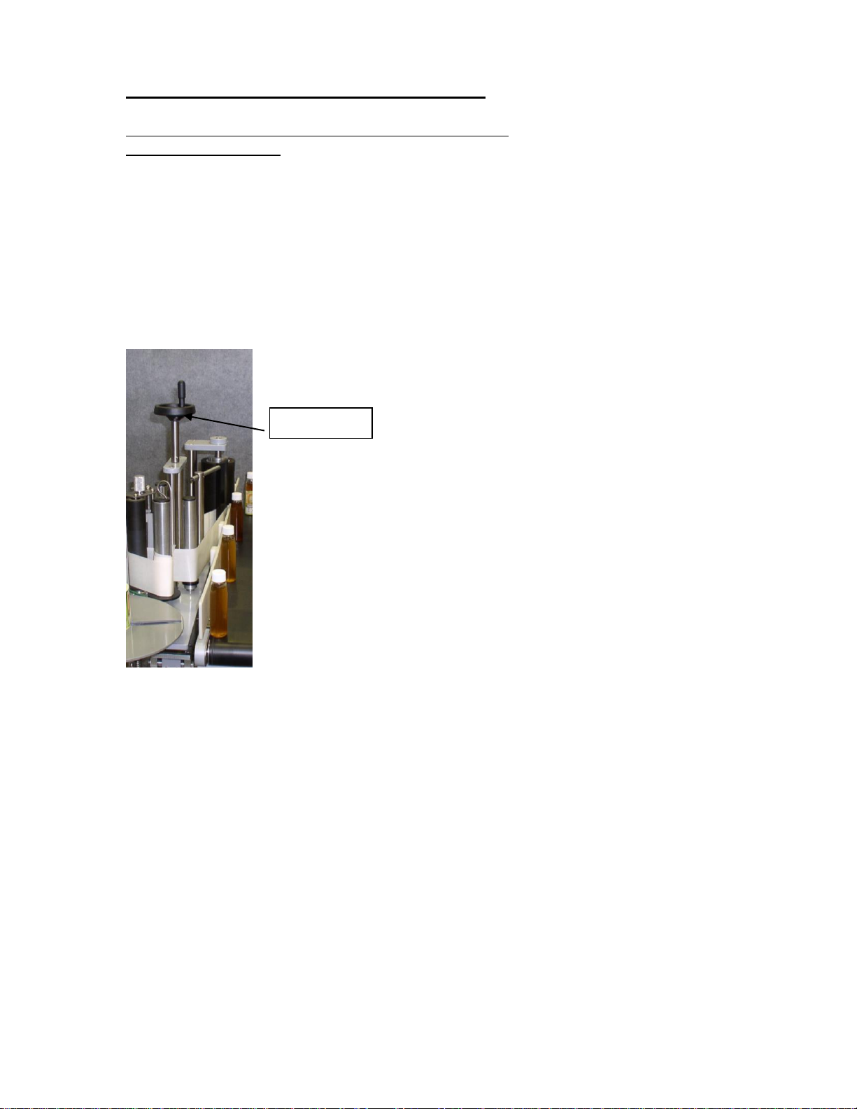
Label tension brush –The Label Tension Brush Assembly applies pressure to the label
surface to create some drag on the label to increase label web tension.
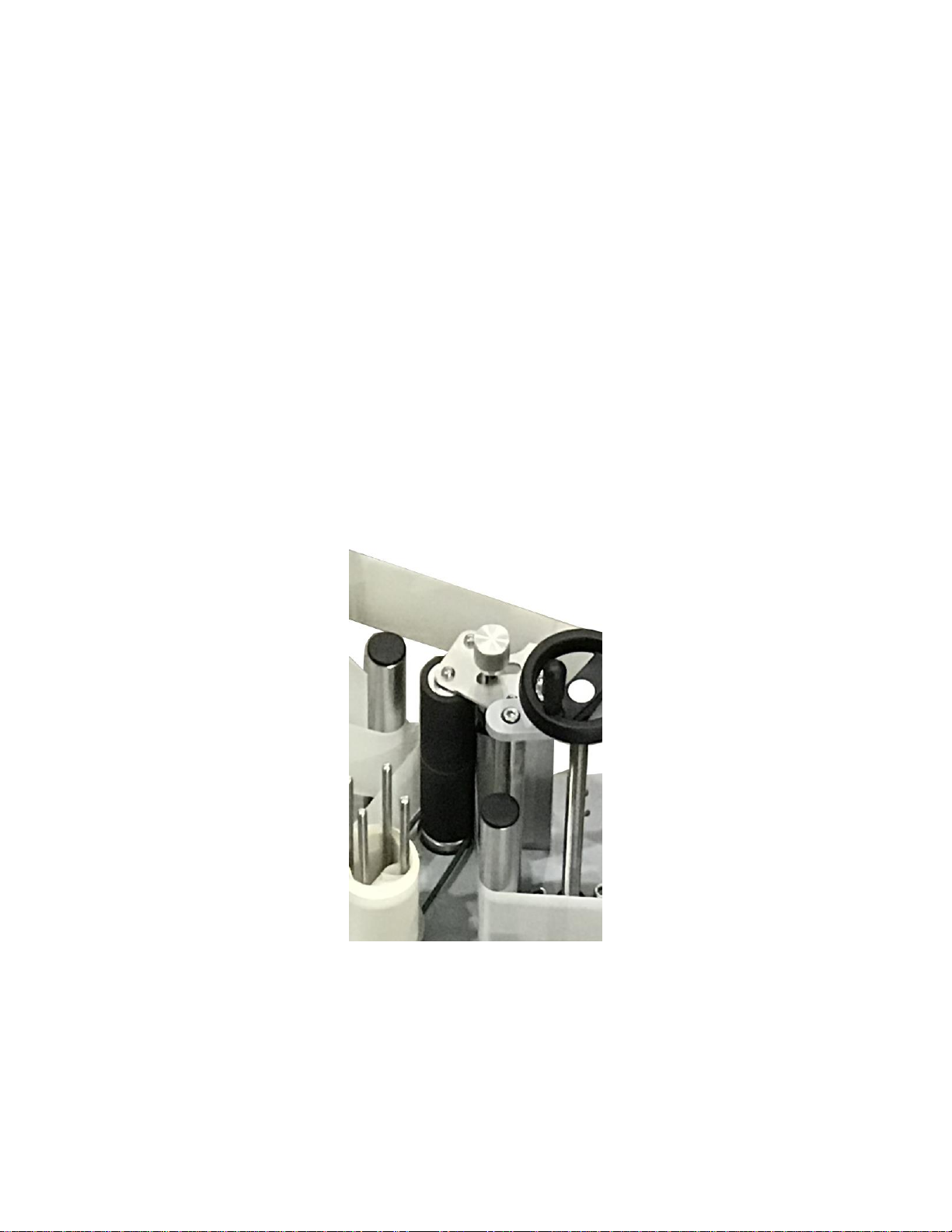
Peel Plate –The Peel Plate gives the labels a sharp edge to peel off the backing paper for
label application. The peel plate angle is adjustable. This is to get the label web tracking
correctly and it is important to achieve this before even applying a label to a product.
If the label web is tracking up, the peel plate must be tilted down to level out the label
web. If the label web is tracking down the peel plate must be tilted up. To adjust the peel
plate angle, follow the steps below.
•At the top of the mounting post for the peel plate bars there is a 6mm grubs crew.
There is also one at the bottom of the post. (DO NOT TOUCH THIS ONE)
•To change the angle of the peel plate, loosen the top grub screw.
•By sliding the peel plate bar left or right, the peel plate angle will change. Once
the desired position is obtained, re tighten the grub screw to hold the peel plate
bar into position.
If the label web is tracking correctly when just running labels out not onto a product and
there is a problem after application. The fault is not the label tracking. The likely causes
are passably the incorrect label ejection speed or that the product is not running square
and straight in the capture assembly.

10
Pinch Assembly –The Pinch Assembly is a most important part of the whole label head
assembly. This assembly controls the label movement and application. The pinch
assembly works by holding the label backing paper between a rubber drive roller and a
knurled aluminum pinch roller, as the rubber roller is turned by the servo motor, the
backing paper is pulled which in turn causes the label to be released from the backing
paper as the backing paper pulls around the peel plate.
The tension of the pinch roller can be adjusted by twisting the spring block towards the
rubber roller increasing the spring tension. There is no requirement to over tension the
pinch assembly, use only the tension required to create an even pull on the backing paper.
The rubber drive roller must be kept clean at all times to achieve the maximum grip
available. Turpentine is often the best cleaning agent for the rubber roller.
When threading or removing the backing paper from the pinch assembly, a handle is
provided to pull open the pinch roller to release the backing paper or make an opening to
thread the backing paper.
When threading the labels backing paper trough the pinch assembly, it is often easier to
have the label head turned off, the rest the backing paper in the pinch are and then simply
turn the rubber roller with your hand. The backing paper will be pulled through the pinch
assembly. Once the backing paper can be grabbed from the opposite side it was threaded,
grasp the backing paper with on hand and open the pinch roller with the other. The labels
backing paper can now be pulled freely through the pinch assembly to the waste spool.
Fig. 9

11
2.3.1 LABEL HEAD TILT VERNIER
Label Head Tilt Assembly –The label head has the possibility of adjusting its tilt left
and right. This is used to straighten labels on the product. If a label is adhering on an
angle every time a label is applied, this adjustment is used to have the label apply
straight. On one end of the tilt assembly is two locking plates. These plates lock the tilt
mechanism into position after an adjustment has been made.
To make an adjustment, loosen the locking bolts on the locking plate. Underneath the tilt
plate is a threaded bolt. This bolt acts as an adjustment tool for the tilt mechanism. By
adjusting this bolt up or down a different angle of label application is achieved. Make an
adjustment to the bolt as needed and on completion, tighten the locking bolts on the
locking plates to secure the tilt into position.
Fig. 10
Please note that if the label is skewing in both directions in the run, tilting the label head
will achieve nothing. This is an indication of a faulty product. Only make tilt adjustments
if the label is skewing in the same direction every time.
Threaded Bolt
Locking Plates

12
ORIENTATION MODULE
The orientation module is designed for labelling round containers with a single label up
to 100% label wrap of the product. Also, the Orientation Module makes it possible to
label a product requiring a front and back label off the same label web.
This is achieved by using a motorised drive roller with two pneumatic idler rollers. As the
product is transported along the product conveyor it will be captured by the orientation
idler roller set and product will be rotated for orientation.
Figure 11
Note: the correct set up is achieved when the product rotates evenly without leaning or
lifting off the product conveyor.
The height of the rollers is adjustable up and down as needed by sliding the mounting
bracket up and down the mounting shafts. The correct height is the same height as the
label is being applied and one that allows the product to stay parallel to the drive roller.
M5 Locking Cap Screw
Idler Rollers
Orientation Sensor
Drive Roller
Product sensor

13
TURN TABLE (Not fitted to all Machines)
Some David labellers may be fitted with turn tables. There are no adjustments on the turn
table. To operate the turn table, turn on the rocker switch shown in figure 4.
Figure 12
Figure 13
Turn Table Power Switch

14
GUIDE RAILS
One side of the conveyor has fixed guide rails, this is the datum edge. The other side of
the conveyor has moveable guide rails. The rail must be adjusted for the width of the
product.
To adjust the rail, loosen the star knobs as shown in figure 9.
Fig 14
STAR KNOBS

15
2.4 CONTROL PANEL
Control Panel Functions
Emergency Stop –
The emergency stop button is used to cut power to the machine in the event of an
emergency, or to turn the machine off.
Push to activate the stop and twist knob in an anti-clockwise direction and release to reset
the stop.
Power Stop Button- The power stop button isolates power in the same way as the
emergency stop, simply press the stop button to cut all power to the machine.
Power Start Button - The power start button applies power to the machine when pressed.
Note: the emergency stop button knob must be released to re start the machine.
SENSORS
There are two sensors on the machine and are as follows:
PRODUCT SENSOR –The purpose of the Product Sensor is to Sense the product
travelling on the conveyor and triggers the start of the labelling sequence.
LABEL GAP SENSOR –The Label Gap Sensor senses the gaps between the labels and
triggers the end of the labelling sequence.
ORIENTATION SENSOR –On some applications the label is to be orientated on to a
certain position on the product. The Orientation sensor is used to sense a certain position
on the product and place the label in relation to the position.
Refer to manufactures manuals for setup procedures on the sensors.

16
LABEL HEAD BUTTON OPERATIONS
MAIN SCREEN
Fig 15
From the Main Screen all other screens are accessible. The functions of the buttons are as
follows:
This button accesses the Run screen. Fig 16
This button accesses the Setting screen. Fig 17
This button accesses the Counter Screen. Fig18
This button accesses the Service screen. Fig 19

17
G4 TOUCH SCREEN OPERATOR INTERFACE
The functions of the screens are as follows:
RUN SCREEN
Fig 20
From the run screen the Labeller and the Conveyor/wrapper assemblies can be turned ON
and OFF.
To turn on the Labeller, press the labeller button and the button will
turn green and show labeller ON.
To turn off the Labeller, press the labeller button again and the button will turn grey and
show labeller OFF. Fig 16
To turn on the Conveyor, press the conveyor button and the button
will turn green and show conveyor ON.
To turn off the Conveyor, press the conveyor button again and the button will turn grey
and show conveyor OFF. Fig 17

18
OPERATOR INTERFACE TOUCH PANEL
SETTINGS SCREEN
When the settings button is pressed the screen will change to the first screen of the label
settings. The screens and their operations are as follows:
Fig 21
SETTING SCREEN BUTTONS
PROGRAM –Pressing this button will access the PROGRAM screen were the operator
can LOAD and SAVE program settings.
MENU+ - Pressing this button will allow the operator to index up through the labelling
settings.
MENU- - Pressing this button will allow the operator to index down through the labelling
settings.
RUN –Pressing this button will return the operator to the RUN screen.

19
LABELLING OPERATION SETTINGS
The operation of the touch screen controller is laid out in a series of steps.
The machine follows each of these steps in order and performs the function of each step,
to skip a step, set the value setting to zero on that variable. i.e. if two labels are required,
then to put a value setting in label 1 and label 2.
VARIABLE SELECTION
Fig 22
To switch through this variable menu, press the menu “MENU +”on the screen to go up
the menu and “MENU -”to go down the menu or back step.
The variable settings “MENU +” are as follows:
1. Speed –This is the speed of the label ejection and is displayed in meters per
minute. Set the value to get the speed required. To change this setting, touch the
number panel on the screen, this will activate a new pop up a keypad. Using this
numeric keypad, key in the new number value required then press ENTER.
Fig 23
2. Flag steps –This is for setting where the label stops, it operates by receiving a
signal from the label gap sensor to stop, after receiving this stop signal, the motor
moves by the number set in the values. To change this setting, touch the number
panel on the screen, this will activate a new pop up a keypad. Using this numeric
keypad, key in the new number value required then press ENTER.
Fig 24

20
3. Start Delay - This is the delay from the product sensor detecting the product to
the close of the capture module. When using the wrap capture module to hold the
product in place, set this delay to extend the pneumatic piston to hold the product
at the right time in the centre if the wrapping module. If not using this feature, set
value to 0000. To change this setting, touch the number panel on the screen, this
will activate a new pop up a keypad. Using this numeric keypad, key in the new
number value required then press ENTER.
Fig 25
4. Piston extend –When using the round container wrap module on the machine,
this is the time delay required to allow the pneumatic piston to extend and hold
the product to stabilise it within the capture module prior to labelling. When not
using the wrap option, set the value to 0000. To change this setting, touch the
number panel on the screen, this will activate a new pop up a keypad. Using this
numeric keypad, key in the new number value required then press ENTER.
Fig 26
Table of contents