B-Max B-Home Round 25 Technical manual

Code EBM0002 - 07/2016 - R2
Code
INSTRUCTIONS FOR USE,
INSTALLATION AND MAINTENANCE
B-Home Round 25
B-Essential Round 50
Before installing and using the burner, read this manual carefully and keep it close to
the burner.
PELLET BURNERS
EN
2
INTRODUCTION
Dear Client,
We would like to thank you for having chosen a
B-Max
appliance.
The model chosen by you, is a high-performance product, with an advanced technological conception, high reliability and
excellent construction quality.
We advise you to entrust the running and maintenance of this appliance to qualified professionals that you know, and also
to use only original spare parts when needed.
This manual contains important guidelines and suggestions which should be complied with in order to obtain a simple in-
stallation and the best possible use of the appliance.
INDEX
SYMBOLS USED IN THE MANUAL AND THEIR MEANING
l
WARNING
To indicate information about particular details.
m
WARNING CAUTION
To indicate information about particularly sensitive details.
a
WARNING DANGER
To indicate actions, which, if not carried out correctly, can cause injuries of a generic kind or can cause malfunc-
tions or material damage to the apparatus; so they require special attention and proper preparation.
f
WARNING DANGER ELECTRICITY
To indicate actions, which, if not carried out correctly, can cause injuries from electricity; so they require special
attention and proper preparation.
d
IT IS FORBIDDEN
To indication actions which MUST NOT be taken.
1 General information 3
1.1 General warnings 3
1.2 Restrictions 3
1.3 Conformities 3
1.4 Structure 4
1.5 Burner description 5
1.6 Safety devices 5
1.7 Size 5
1.8 Accessories 5
1.8.1 Supply feed cochlea: size and weight 6
1.8.2 Pellet container: size and weight 6
1.9 Technical data 6
1.10 Operational wiring diagram 7
1.11 Running 8
1.12 Pellet 8
1.13 Control Panel 9
1.13.1 Viewings on Screen 9
1.14 User parameters 10
2 Installation 11
2.1 Delivery and identification of the product 11
2.1.1 Identification 11
2.1.2 Contents of the package 11
2.2 Handling 11
2.3 Installation location 12
2.4 Mounting the burner 12
2.5 Mounting of the loading cochlea and the pellet
container 13
2.6 Release of exhaust fumes 13
2.7 Electrical connections 13
3 Start-up 14
3.1 Before starting up the burner 14
3.2 First ignition 14
3.3 Checks to carry out after the first ignition 14
3.4 Automatic shut-down and subsequent start-ups 14
3.5 Pellet calibration 14
3.6 Programming of user parameters 15
3.7 List of parameters 17
3.7.1 Technical parameters 17
3.8 Alarm messages 18
3.9 Problems - Possible causes - Solutions 18
4 Maintenance 19
4.1 Periodic maintenance 19
4.2 Disposal 20

3
1 GENERAL INFORMATION
1.1 General warnings
l
WARNING
–This manual is the property of
Elmec Group S.r.l.
and its contents may not be copied or passed on to third parties.
All rights reserved.
–The appliance is not designed to be used in environments with a potentially explosive atmosphere.
–This manual is an integral part of the product; make sure that it is always kept with the appliance, even in the
case of sale/transfer to another owner, so it can be consulted by the user or by the staff authorised to carry out
maintenance and repairs. Read this manual thoroughly before using the appliance in order to ensure operation-
al safety.
–In the event of doubts concerning the conditions and/or working of the appliance or its parts, the local distrib-
utor should be contacted for further information.
–Only use original spare parts or ones approved by the manufacturer in order to avoid damage to the product.
–In the event of damage to the packaging of the goods, inform the courier and the product supplier of the prob-
lem immediately.
–Carry out the operating tests on the appliance and inform the supplier of the product of any anomalies or run-
ning defects found.
1.2 Restrictions
d
IT IS FORBIDDEN
–Do not use the appliance in areas with a potentially explosive atmosphere.
–Do not carry out modifications to the product without the written authorisation of the manufacturer.
–Do not open the door of the boiler when it is in use.
–Do not store inflammable materials close to the burner, to minimise the risk of fire.
–Do not leave the appliance exposed to the weather.
–Do not install the appliance onto heat generators (boilers, water heaters) situated in places which are poorly
ventilated or are very damp. The vents in the building must be sufficiently large to guarantee complete com-
bustion.
–Do not touch the appliance with parts of the body which are wet, or damp and/or with bare feet.
–The appliance must not be used by children or by people who are inexperienced.
1.3 Conformities
The burners
B-Home Round 25
and
B-Essential Round 50
are in compliance with European directives:
–Machinery Directive 2006/42/CE
–Electromagnetic Compatibility Directive 2014/30/CE
–Low Voltage Directive 2014/35/CE
as stated in the Conformity Certificate supplied with the appliance.
4
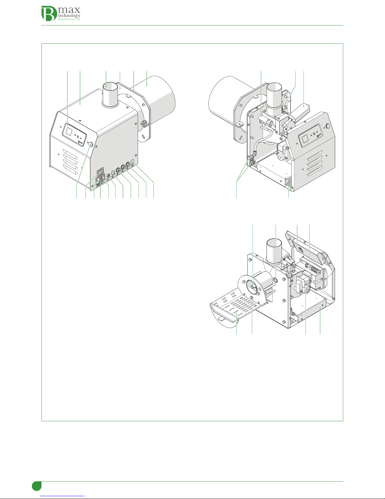
1.4 Structure
1 2
16 22 211517
3 54 6
1823 24 25
18 19 20
29 28 27 26
14 13 12 11 10 9 8 7
1
Control Panel
2
Carter housing
3
Socket connection hose
4
Boiler connection flange
5
Washer
6
Combustion chamber
7
Connection for optional applications
8
External thermostat connection
9
Boiler water probe connection
10
External cochlea motor connection
11
Manual pellet loading button
12
Fuse (3.15A delayed)
13
Main switch
14
Fuse (4A)
15
Power socket (230 volts)
16
External cochlea fan power socket
17
Connection for use with a PC
18
Flame detection photocell
19
Burner safety thermostat
20
Internal cochlea gear motor
21
Combustion air vent
22
Compressed air combustion kit (OPTIONAL)
23
Internal cochlea
24
Display card
25
Electronic card
26
230V/24V transformer
27
Burner fan
28
Ignition resistance
29
Fuel grill

5
1.5 Burner description
The burners
B-Home Round 25
and
B-Essential Round 50
are very versatile and are able to cover a great many functions, from
installation on new generation boilers, bread ovens and hot air generators to the transformation of old boilers
They are made up of a round combustion head, a variable-speed main ventilator, a reliable start-up system, thanks to the
flame detection photocell, an internal cochlea for feeding the fuel and they are designed so a compressed-air self-cleaning
kit can be installed.
They must be completed with a fuel feeding system made up of a cochlea, with a flexible tube connected to the burner and
by a pellet container, which is supplied separately , as an accessory.
The burners and the whole system are managed by a control panel with a microprocessor fitted onto the device, which,
as well as managing all the functions, also permits the programming of time bands; this is useful so the machine only runs
when it is needed.
1.6 Safety devices
The burners
B-Home Round 25
and
B-Essential Round 50
are fitted with the following safety devices:
–Burner safety thermostat
–Firebreak valve (optional)
1.7 Size
A AB H MI
N
F G
C E
D
L
Model A
[mm]
B
[Ø mm]
C
[mm]
D
[mm]
E
[mm]
F
[Ø mm]
G
[mm]
H
[mm]
I
[mm]
L
[mm]
M
[mm]
N
[mm]
Round 25 47,5 140 101 263 22 60 232 272,5 249 30 21 543
Round 50 33,5 168,5 77 263 17,5 60 232 272,5 249 30 21 543
1.8 Accessories
The following accessories can be ordered separately from the burner. They should be used to ensure that the burner is prop-
erly connected and integrated.
Model Code
Cochlea (Ø 60 mm) EBL0003-P01
Pellet container EBT0001-P01
Pellet container EBT0002-P00
Compressed air kit EBK0018-P00

6
1.8.1 Supply feed cochlea: size and weight
G
B C D F
A
E
H
A
[mm]
B
[mm]
C
[mm]
D
[mm]
E
[Ø mm]
F
[mm]
G
[Ø mm]
H
[mm]
Weight
[Kg]
1760 190 1168 402 60 190 60 120 9
1.8.2 Pellet container: size and weight
A B
C
Description Capacity
[Kg]
A
[mm]
B
[mm]
C
[mm]
Weight
[Kg]
Pellet container EBT0001-P01 280 750 650 1252 70
Pellet container EBT0002-P00 300 800 800 1300 57
1.9 Technical data
DESCRIPTION U/M
B-Home Round 25 B-Essential Round 50
Burner power kW 12 ÷ 34 12 ÷ 50
Power supply V~Hz 230~50 230~50
Average power consumption W 60 60
Ignition W 230 230
Fuse (delayed) A 3.15 3.15
Noise level dBA 35 40
Length of flame mm 200 300
Boiler combustion chamber minimum size
Height mm 300 400
Width mm 300 350
Depth mm 350 450
Flue draw Pa 20 20
7
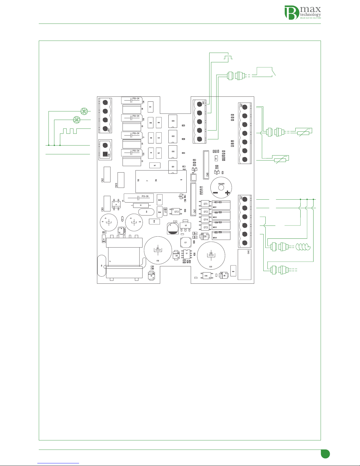
1.10 Operational wiring diagram
VPC
VCE
RS
230V/50Hz
M1
M2
24 Vdc
N
F
F
F
F
+
–
–
–
–
SA
ARC
TE
FR
PM1
VPC
Main combustion valve
VCE
External cochlea fan
RS
Resistance
PM1
External cochlea button
TE
External thermostat
SA
Water probe
FR
Photoresistance
M1
External cochlea
M2
Internal cochlea
ARC
Compressed air
8
1.11 Running
The running of the appliance is controlled from a control panel with a microprocessor which programmes the following
phases:
–When a request for heat is sent in start-up mode the main fan, the external cochlea and the internal loading cochlea start
up to supply the necessary quantity of pellets for ignition. The internal cochlea starts up 8 seconds later than the external
cochlea;
–When the pellet loading for ignition is finished, the ignition resistance is powered electrically, and this ignites the flame
the brightness of which is recorded by the photocell within a max. of 20 minutes (safety time). In the event of non-ignition,
the burner goes into SHUTDOWN mode. In the event of a SHUTDOWN, in order to reactivate normal running conditions,
it is necessary to disconnect the appliance from the mains, remove the cause of the malfunction, and then reconnect it to
the power supply;
–After the flame has been correctly detected, the appliance starts to run normally with a gradual increase in power supply
until the maximum value programmed is reached, and the appliance continues to operate in modulation until the pro-
grammed water temperature for the boiler is reached, or that of a water storage heater if one is installed. While the burner
is running, the external and internal cochleas also work according to the programmed ON and OFF times;
–Once the programmed temperature has been reached, the cochleas, both internal and external, are stopped by the control
panel, and the pellets remaining in the combustion chamber continue to burn;
–When the brightness of the photocell goes below 20 lux, the fan speed increases to clear the combustion chamber of the
last residue and then it stops.
The burner is then ready for the next start-up.
m
WARNING CAUTION
–The programming of the parameters MUST be carried out EXCLUSIVELY BY QUALIFIED TECHNICIANS AUTHOR-
ISED BY
Elmec Group S.r.l.
, and only after the Password has been given.
–For the working and shut-down periods of the burner, whether the "time bands" are activated or not should
be taken into consideration.
–If the COMPRESSED AIR KIT is also present, cleaning of the combustion chamber takes place at the beginning
and at the end of each operational cycle of the burner.
d
IT IS FORBIDDEN
Programming of the technical parameters from the User Menu.
1.12 Pellet
The devices are designed and built to
burn quality pellets
which have the following characteristics:
Description U/M Pellet
Diameter mm 6 Din Plus
Length mm 25 (max)
Density Kg/m3650
Lower heating power kWh/kg 5
Percentage of humidity % Max 8 (of the weight)
Percentage of ash % Max 1 (of the weight)

9
1.13 Control Panel
2 13
C A
D E F
B
1
CONTROL PANEL
2
OPERATING KEYS
(
Pressure SHORT (1 second)
Access to User Menu
Pressure LONG (> 2 seconds):
Check of programmed data
Pressure LONG (> 12 seconds):
Reset of all parameters. WARNING!!! With this operation, all previous pro-
gramming will be erased (*).
NB: to exit from the programmed data verification phase, press the key
(
for more than 2 seconds.
F
Pressure SHORT (1 second)
Modification of power
Pressure LONG (> 2 seconds):
Ignition/shut-down of burner
)
Pressure SHORT (1 second)
Temperature modification
Pressure LONG (> 2 seconds):
Access to Installer's Menu. To gain access it is necessary to know the pass-
word (*).
NB: to exit from the "Installer Menu", press the key
(
.
3
SCREEN
A
Date
B
Burner state
C
Time
D
Parameters
E
Power consumed
F
Boiler water temperature
(*) Actions only to be taken by AUTHORISED INSTALLERS.
1.13.1 Viewings on Screen
Power
Burner power
Tk1
Loading time of external cochlea (SI)
Tk2
(NOT USED)
Lux
Brightness intensity
Ext
Fan speed of external supply cochlea
l
WARNING
At the bottom of the screen You can see the "Guidelines", which
are useful for the operator.

10
1.14 User parameters
Main display
To enter boiler water
temperature (10-90°C)
To enter burner power
levels (1-2-3-4-5)
To enter "LANGUAGE"
To enter "TIME"
"HOUR FORMAT"
"DATE"
"TEMPERATURE"
"BRIGHTNESS"
ENABLE TIMER
"WEEKLY TIMER"
"TYPE OF FUEL"
"INFORMATION"
(*)
(*)
(*)
(*)
(*)
(*)
(*)
(*)
(*)
(*)
(*) To enter User Parameter programming (see paragraph "Programming of user parameters".

11
2 INSTALLATION
2.1 Delivery and identification of the product
The appliances
B-Max
are delivered in separate packs and are placed on wooden pallets.
4
4
12
4
3
Burner (1)
It is supplied packed into a duplex corrugated cardboard box.
Backfire safety device (2)
It is supplied packed into a duplex corrugated cardboard box.
Pellet supply cochlea (3)
It is supplied packed into a duplex corrugated cardboard box and it is sup-
plied separately from the burner.
Label (4)
It is placed on the outside of the packaging for identification of the product.
2.1.1 Identification
The identification of each pack is possible by means of the label placed on the outside of every package.
l
WARNING
On receipt of the product it should be checked that the delivery is complete and in the event of any non conform-
ities or complaints, the organisation that sold the appliance should be contacted.
2.1.2 Contents of the package
Burner
–Burner
–O-ring
–Socket pipe
–Flexible hose
–Seal and burner support flange
–Power supply cable
–Water probe
–Documentation envelope
The following material is supplied in the documentation envelope:
–Instruction manual
–Warranty certificate
–Declaration of conformity
–Catalogue of spare parts
–Bag of bolts and screws
–Connectors for electrical connections
Safety anti-backfire device
–Firebreak valve (optional)
Pellet supply cochlea
–Cochlea complete with:
-Fan electrical cable
-3.15A Delay Fuse.
2.2 Handling
The burners
B-Home Round 25
and
B-Essential Round 50
have been designed to operate solely with heat generators that have
a vacuum combustion chamber, so the smoke duct and the flue must be designed and realised to satisfy these requirements.
The joints must be sealed and resistent to the maximum temperature levels that the fumes can reach.
12
2.3 Installation location
The pellet burner must be installed in a place that conforms to current Legislation, Regulations and Directives against fire
hazards.
The positioning of the devices and the components must be organised so that there is enough space for maintenance work,
cleaning and soot removal from the burner, the boiler and the flues.
a
WARNING DANGER
The room must have sufficient ventilation vents which are of the right size and are positioned correctly.
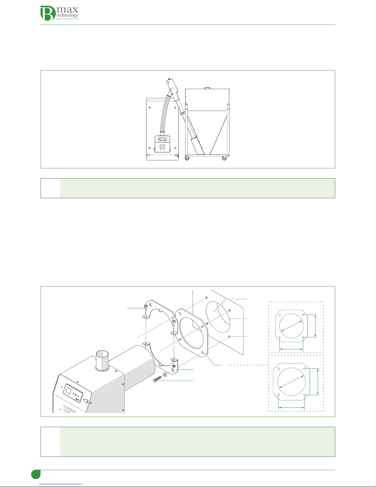
2.4 Mounting the burner
When mounting the burner onto the boiler:
–check that the opening (1) of the door (2) of the boiler is sufficiently large to allow the combustion chamber of the burner
to pass through it. If this is not the case, adapt it to the diameter
–make four threaded holes (3) (M8) for fixing the burner support flange
–position the seal (4), supplied with the burner, between the flange (5) and the door (2) of the boiler
–push in the 4 screws (6) (M8) but ONLY tighten the two screws which hold the lower split-flange. The two screws of the
upper split-flange must ONLY BE PLACED but not tightened.
–Insert the combustion chamber of the burner into the boiler as far as is necessary
–tighten the two semi-flanges with the screws (7) and the screws (6), which were previously just placed in position
6
7
5
1
4
2
3
Round 25
Round 50
159
159
Ø 172
135
135
Ø 142
a
WARNING DANGER
–The burner
MUST
be mounted
ONLY
in the position shown in the diagram. Any other position
is FORBIDDEN
.
–The flame will propagate in a straight line, through the hole of the burner combustion chamber.
13
a
WARNING DANGER
The mounting of the burner on the boiler must be sealed to avoid any dangerous smoke escaping. Use the seal
supplied by the manufacturer.
2.5 Mounting of the loading cochlea and the pellet container
The mounting of the external loading cochlea and of the pellet container is very important if the burner is to run correctly.
It is advisable to buy and use the original accessories, because they have been specifically designed to ensure the correct
running of the burner.
l
WARNING
The manufacturer
Elmec Group S.r.l.
DOES NOT ACCEPT RESPONSIBILITY for any damage to people, animals or
things caused by the use of components that are not original.
2.6 Release of exhaust fumes
The burners
B-Home Round 25
and
B-Essential Round 50
have been designed to operate solely with heat generators that have
a vacuum combustion chamber, so the smoke duct and the flue must be designed and realised to satisfy these requirements.
The joints must be sealed and resistent to the maximum temperature levels that the fumes can reach.
a
WARNING DANGER
–Any applications which are different from the one specified in the manual can cause fire.
–Non-insulated exhaust ducts are a potential source of danger.
–It is possible to install a flue valve which conforms to applicable legislation
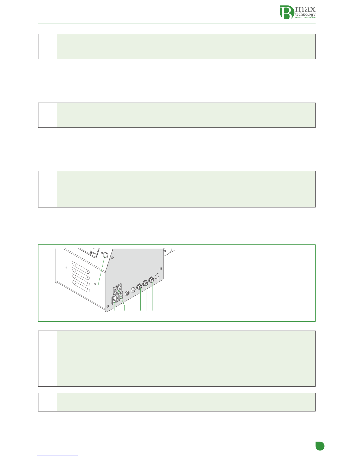
2.7 Electrical connections
The burners
B-Home Round 25
and
B-Essential Round 50
have been wired in the factory and it is essential that only profession-
ally-qualified personnel carry out the work reported below.
21 3 4 5 76
1
Power supply socket (230V~50Hz)
2
External cochlea fan power socket
3
External cochlea motor
4
Boiler water temperature probe
5
External thermostat connection
6
Connection for use with a PC
7
Connection for optional applications
f
WARNING DANGER ELECTRICITY
Please remember that
IS OBLIGATORY
:
–to use an omnipolar circuit breaker switch, a disconnect switch in conformity with EN regulations
–to use an L (phase) - N (Neutral) connection
–to connect the earth to an efficient plant grounding device. The manufacturer
Elmec Group S.r.l.
DECLINES ANY
RESPONSIBILITY for any damage to people, animals or things, caused by the absence of grounding of the appli-
ance and of the non-compliance with anything specified in this manual.
d
IT IS FORBIDDEN
Use the water pipes for the grounding of the appliance.

14
3 STARTUP
3.1 Before starting up the burner
Before starting up the appliance check that:
–the burner is correctly mounted on the boiler door and that this latter is firmly closed
–the cochlea and the burner flexible connection hose are positioned correctly
–the pellet container has been filled
–the water temperature probe has been correctly positioned
–the boiler and the plant has been filled with water
–the hydraulic circuit valves are open
–the fumes exhaust duct has been set up properly.
3.2 First ignition
Connect the burner power supply, positioning the plant main switch and the main burner switch in the "ON" position , and
check that the screen lights up.
The burner has already been calibrated for maximum power in the factory, so for the first ignition just press the Fkey for
about 2 seconds and wait for the flame to light.
Leave the burner in the continuous running mode, at maximum power for about 15 minutes, and then with a flue gas analys-
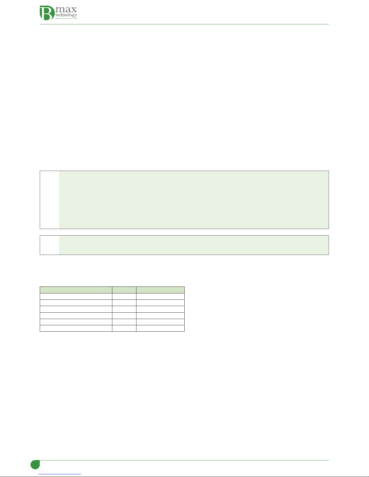
er check that the values recorded are close to the ones indicated in the table:
Description U/M Correct vlaue
O2% ~ 10
CO (average) mg/cm3< 500
Exhaust temperature °C 120 ÷ 200
Press the Fkey to turn off the burner and leave it to cool.
l
WARNING
This operation must be carried out ONLY by authorised and qualified technicians.
3.3 Checks to carry out after the first ignition
After the first ignition, with a cold burner:
–disconnect the pellet supply tube from the burner
–open the boiler door and check that on the combustion chamber grill THERE IS NO unburnt material. If this is not the case,
it is necessary to modify the settings on the basis of the specific needs (the combustion air and the quantity of fuel) and to
repeat the "FIRST IGNITION" phase previously described.
3.4 Automatic shut-down and subsequent start-ups
Once the request for heat has been satisfied, the pellet feeder stops, and the burner regulates its speed for the burning of
the residual pellet, present in the combustion chamber, up to the minimum luminance (20 lux) measured by the photocell.
When 20 lux is reached, the fan goes up to maximum velocity (for 4 minutes) to clean the combustion chamber of any resid-
ual matter and then it turns off.
At every request for heat all the phases described previously are repeated.
3.5 Pellet calibration
The calibration of the quantity of pellets necessary for ignition and for running the burner is achieved as follows:
–fill the pellet container
–pull out the flexible hose from the burner socket and place it in a recipient (basin)
–Check that there are no requests for heat
–Connect the burner power supply, positioning the plant main switch and the main burner switch in the "ON" position , and
check that the screen lights up
–press the button (manual loading) until the pellets are falling continuously into the recipient (the cochlea is full of pellets)
–empty the recipient and press the button again (manual loading) for about 6 seconds (loading time for max power 5),
controlling the time with a stopwatch, and weigh the pellets which have fallen into the basin.
15
Calculate the maximum burner power using the following formula:
Y*5/45*3,6= z (kW/h)
where
Y
Quantity of pellets (in grams) weighed in 6 seconds (loading time for max power)
5
p.c.i. of the pellets
45
max. cochlea time
3,6
pellets in Kg/h.
m
WARNING CAUTION
If the type of pellets being used is changed (not advisable) the calibration of the pellets MUST be repeated, be-
cause the combustion characteristics will change.
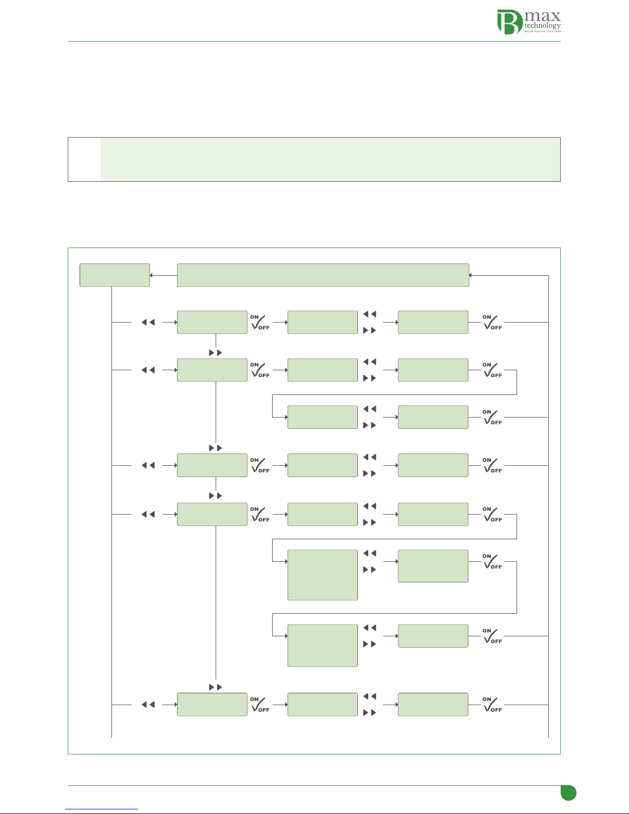
3.6 Programming of user parameters
The programming of the user parameters can be done following the flow diagram above, after connecting the burner to the
mains.
To enter "LANGUAGE" To conrm selection To select
EN - IT - ES - FR - DE
Main display To conrm selection and go back to Main Display
o
"DATE" View
month
To select current
month
o
To enter
"TIME"
"HOUR FORMAT"
View current
time oTo programme or
modify time
oTo select
12 or 24 hours
To programme or
modify date
24/03/2015 o
To programme
or modify
current day
To conrm setting
and to move
to day setting
o
To programme or
modify year
To conrm setting
and to move
to year setting
o
View 12 or 24 hours
format
"TEMPERATURE" oTo select
F° or C°
View
F° or C°
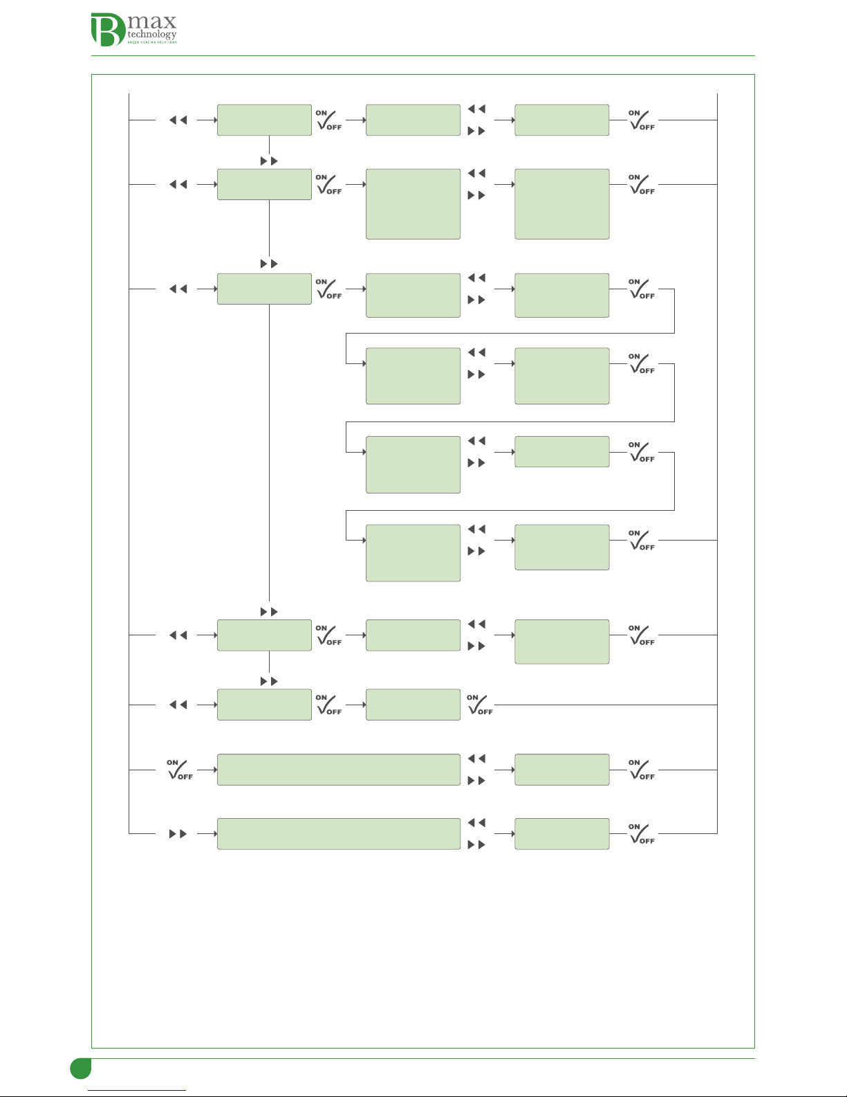
16
"BRIGHTNESS"
View brightness on
display
To regulate brightness
levels
o
"WEEKLY TIMER" View Band 1 of 7
programmable bands
To enter programming
of times
o
“ENABLE TIMER” View operation
enabling in line with
programmed time
bands
oTo enable operations in
line with programmed
time bands, or not,
YES/NO
To programme minute
start time for Sunday
operations
To programme hour
start time for Sunday
operations
o
To programme or
modify year settings
To conrm setting and
move to year setting
o
Proceed in the same
way for all the days of
the week (*)
To conrm setting and
move to start time for
Monday
o
"TYPE OF FUEL" oTo select the type of fuel
used (A-B-C-D)
To view type of fuel
used
oTo select the desired
level
"INFORMATION"
To enter burner power levels (1-2-3-4-5)
oTo select the desired
temperature
To enter boiler water temperature (10-90°C)
View software version
(*)
1
When the Saturday times have been programmed, press the key Fto save the programmed times and to prepare
for programming the Band 2 times
2
Press the key )to select Band 2. Press the Key to confirm Fand enter the level for programming the start and end
of running times
3
To programme the times, proceed as described above
4
Repeat the same procedure to programme the times of all the available time bands (up to 7)
To prevent the burner working in a particular time band, programme both the start time and the end time at
00.00.
17
3.7 List of parameters
3.7.1 Technical parameters
Viewing of screen Description U/M Field Factory default setting
Round 25 Round 50
TECHNICIAN - Starting up
Δ temp. -
Hysteresis for water regulation temperature. When the set tem-
perature is reached, the burner shuts off. If the temperature of the
hysteresis value programmed falls below the set value, the burner
starts up again.
°C 2 ÷ 30 2
Δ temp. +
Maximum value the water temperature can reach beyond the set
value. If the temperature exceeds the set value of the amount se-
lected (5°C) the burner shuts off and only starts up again when the
temperature programmed in the temperature control parameter is
reached "∆ temperature ceck".
°C 1 ÷ 5 5
External thermostat Enables the use of an external thermostat (e.g. TA or TB). On / Off Off
Viewing on display h2oEnables viewing on the screen of the temperature programmed for
the water in the boiler. On / Off On
110V / 60Hz To be activated in the countries with this mains voltage. YES / NO NO
STARTING UP - Power
Pellet pre-loading (s) This parameter sets the first pellet loading time. sec 0.0 ÷ 60.0 10
Compressed air (s) Duration of cleaning process with compressed air. sec 0.0 ÷ 20.0 6,00
Initial ventilation Fan intensity in the ingnition phase after the "pellet pre-loading"
phase (“precarico pellet”). rpm 0 ÷ 300 160
Minimum lux start-up Minimum brightness to establish a regular ignition. Lux 0 ÷ 1000 60
Lux shut-down
If the brightness goes below the level recorded during the time
regulated within the Dead Band parameter ("Banda Morta"), the
burner shuts down. If this happens during normal running of the
appliance, the signal ERROR appears on the display.
Lux 0 ÷ 100 20
Dead band (s)
This is the time during which the optical sensor must continuously
record a value higher than the parameter "Minimum lux start- up"
("Lux minimo avvio"). Every time the values recorded go below the
parameter Minimum lux start- up ("Lux minimo avvio"), the count
starts up again.
sec 0 ÷ 600 60
Flame stabilisation (m) Time deemed necessary for stabilisation of the flame, after which
the burner is enabled to start up. min 0 ÷ 20 1
POWER - Cleaning
Type Type of combustion being used. A-B-C-D A
Fuel supply interval. Time between one pellet reloading and the next. Sec. 1.0 ÷ 90.0 45.0
Start-up Filling Time from external cochlea to start. Sec 0.0 ÷ 30.0 3,0
Fan Fan speed at start. rpm 0 ÷ 300 220
Power 1 Filling Time from external cochlea to Power 1. Sec 0.0 ÷ 60.0 2,0
Fan Fan speed at Power 1. rpm 0 ÷ 300 150
Power 2 Filling Time from external cochlea to Power 2. Sec 0.0 ÷ 60.0 3,5
Fan Fan speed at Power 2. rpm 0 ÷ 300 160
Power 3 Filling Time from external cochlea to Power 3. Sec 0.0 ÷ 60.0 4,5
Fan Fan speed at Power 3. rpm 0 ÷ 300 170
Power 4 Filling Time from external cochlea to Power 4. Sec 0.0 ÷ 60.0 5,5
Fan Fan speed at Power 4. rpm 0 ÷ 300 180
Power 5 Filling Time from external cochlea to Power 5. Sec 0.0 ÷ 60.0 6,5
Fan Fan speed at Power 5. rpm 0 ÷ 300 200
NOTA
The fill-up time depends on the power level programmed and on the type of fuel being used
The fan speed depends on the fuel (type and quantity) and on the flue draw
CLEANING - Shutting down
Cleaning intervals (m)
The interval between the cleaning of the combustion grill carried
out by the burner fan and the cleaning carried out with com-
pressed air.
min 0 ÷ 300 60
Grill cleaning (s) Duration of cleaning process with burner fan running at maximum
power. sec 1 ÷ 180 30
Fan cleaning Fan speed during cleaning phase. rpm 0 ÷ 300 300
Compressed air Presence of compressed air kit (optional). YES / NO NO
External fan Speed of cochlea fan. rpm 0 ÷ 300 300
SHUTTING DOWN - Test Page
Duration
The time during which the ventilator goes on running at max.
power when the burner has been shut down due to an alarm going
off. The objective is to burn all the residual fuel left on the grill. This
cycle is activated when the burner is off.
min 0 ÷ 20 2
Ventilation Fan speed during shut-down phase. rpm 0 ÷ 300 300
External thermostat. This determines the operational mode of the burner once the
environment set value programmed has been reached. min 0 ÷ 90 0

18
Viewing of screen Description U/M Field Factory default setting
Round 25 Round 50
TEST PAGE
Resistance Start-up / Shut-down Ignition resistance. ON/OFF OFF
Cochlea Shut-down Internal cochlea. ON/OFF OFF
Tank shut-down External cochlea. ON/OFF OFF
Internal Fan Burner fan. rpm 0 ÷ 300 0
External Fan. Cochlea fan. rpm 0 ÷ 300 0
Air Start-up / Shut-down Activates 24V electrovalve power supply for the compressed air kit. ON/OFF OFF
Alarm Start-up / Shut-down Activates the 230V output. ON/OFF OFF
NOTA
This checks that the main components of the burner are working correctly.
REMOTE CONTROL
Module Must be activated to connect the GSM module to connector 6 on
the burner. YES / NO NO
3.8 Alarm messages
In the event of a fault or malfunction, the following signs appear on the screen:
Description
Failed ignition
Blackout alarm
Faulty water probe alarm
Fuel finished alarm
TS overheating
Fuel finished
3.9 Problems - Possible causes - Solutions
In the table below are reported the most common problems with their possible solutions.
Problem Possible cause Solution
Failed ignition
Empty pellet container Fill the container
Disconnected or broken external cochlea cable Reconnect the cable or find the break
Ignition resistance broken Check the resistance and/or substitute it
Combuston grill is blocked Pull out the grill and clean it
Internal cochlea blocked Check the internal cochlea and remove any
blockages
Power supply absent Electrical supply to burner not present
Check the mains supply
Check that the electrical cables are connected
correctly
Check that the general switches and the switches
on the burner are in the correct position
Water probe
The probe is incorrectly positioned or connected Check its position and connections
Probe faulty Replace the probe
Fuel finished
Pellet container empty Fill the container
Disconnected or broken cochlea cable Re-establish the connection
Cochlea motor not working Check the motor

19
4 MAINTENANCE
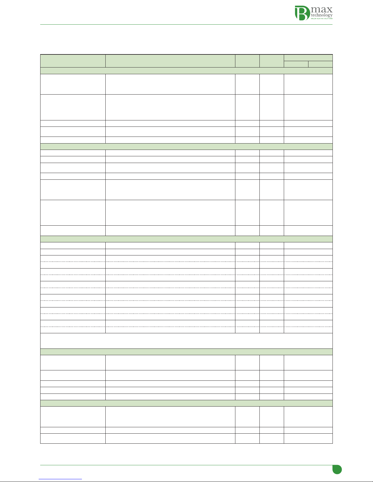
4.1 Periodic maintenance
Periodic maintenance, as well as being necessary for the optimal functioning of the burner and the plant, is required by Law
and if maintenance regulations are not observed, there can be problems or even fines.
Maintenance must be entrusted to and carried out SOLELY by qualified technicians.
The pellet burners
B-Home Round 25
and
B-Essential Round 50
have been designed to require minimal maintenance, the
frequency of which depends directly on the quality and the size of the pellets used (certified or not) and on how the burner
is regulated.
f
WARNING DANGER ELECTRICITY
Before carrying out any maintenance activity, disconnect the appliance from the mains, and put the general
switches on the plant into the OFF position, but also the main ones on the burner and the boiler (if present).
m
WARNING CAUTION
–When carrying our maintenance, all the Personal Safety Equipment required by current Legislation must be
used.
–Periodic maintenance refers to the whole plant in which the burner is installed.
–If non-certified pellets are used, the indications below are rendered null and void, since the characteristics of the
fuel are not known.
–In the event of the use of non-certified pellets,
Elmec Group S.r.l.
DOES NOT ACCEPT RESPONSIBILITY for any
breakages or malfunctions or for any possible harm to people, animals or things, or to the environment.
–The table is only for suggestion purposes and is not binding.
–For cleaning the housing of the burner, use a damp cloth with water and soap or water and methylated spirits,
or with specific non-abrasive products.
Description Periodic
When necessary Weekly Six-monthly Annual
BURNER CLEANING
Combustion chamber - ash and slag x x
Burner fan x x
Internal cochlea
Photocell
Ignition resistance
x x
Pellet container Filling x x
Combustion air suction grill x x
External cochlea bearings
Possible greasing or lubrication x
External cochlea fan x
Control of perishable parts x x
Control of cables and electrical connections x x
PLANT CLEANING
Smoke channel and flue pipe x x
Inside and back part of the boiler x x
Control of perishable parts x x
Control of exhaust fumes x x

20
m
WARNING CAUTION
–After any maintenance work, checks should be made to ensure that the burner is operating correctly.
–Use of the appliance in a poor state of maintenance could cause unexpected and potentially extremely danger-
ous malfunctions.
–If any parts have to be substituted, only original parts should be used.
l
WARNING
The manufacturer
Elmec Group S.r.l.
DOES NOT ACCEPT RESPONSIBILITY for any damage to people, animals or
things caused by the use of components that are not original.
Any modification of or tampering with the burner will render the GUARANTEE, as well as the Manufacturer's RE-
SPONSIBILITY, null and void.
4.2 Disposal
The burner must be disposed of, at the end of its working life, in line with current recycling laws;
for example, the European Directives 2002/95/CE RoHS and 200296/CE RAEE.
This manual suits for next models
1
Table of contents
Popular Burner manuals by other brands


baltur
baltur TBG 2000 MC INSTALLATION, USE AND MAINTENANCE INSTRUCTION MANUAL

Jumbuck
Jumbuck HS-16JCG601-B operation instruction

Riello
Riello RLS 300/E MX Installation, use and maintenance instructions

KitchenAid
KitchenAid KBZU122TSS - 17" Side Burner parts list

Ecoflam
Ecoflam BLU 15000.1 PR manual

Unigas
Unigas HTP90A Manual of installation - use - maintenance