16
Start the Burner
Burner start procedure
(Before proceeding, turn off and lock out electrical
power and close the main leak test cock to shut off gas
to the burner.)
With the power and main gas supply to the burner
turned off, make sure gas has not accumulated in the
boiler or flues.
Check the initial air settings (shutter & band) for input
firing rate. Check the manufacturer’s settings either on
the nameplate shown in Figure 1 or listed in Table 2. If
adjustment is necessary refer to Figure 11 and loosen
the adjustment screws then twist the shutter and/or air
band until the indicators point to the values shown on
the nameplate or listed in Table 2.
With the main gas supply valve closed. Set the limit or
controller to call for heat then apply power to start the
burner. Reset the high and low gas pressure switches
if necessary.
In order to check the function of each component
(i.e: flame safeguard sequence, airflow proving
switch, ignition transformer, gas valves, safety lockout
timing, etc.), with the gas supply closed off, monitor
a complete burner run sequence. Note that the flame
safeguard control will lock out since the fuel supply has
been closed off.
If component operation sequence and function is
correct, reset the flame safeguard and initiate a new
cycle. Monitor the start-up cycle and manually open
1.
2.
3.
4.
5.
the main leak test cock as soon as the flame safeguard
powers the safety shutoff valves. If the boiler room is
quiet you may be able to hear the valve open, if not
you can generally place your hand on the valve and
feel it open. After you have observed main flame for
a brief time, trip any of the switches in the limit string
to shut the burner down. Monitor the flame and safety
shutoff valves to assure that shutdown is controlled by
the valves and that they operate properly. With this
test passed you may safely initiate automatic start-ups
on subsequent cycles.
Verify input firing rate
Clock the meter for CFH and calculate the
input firing rate. Compare the calculated rate to
the specified input for the boiler found on the
specification sheets and on the rating plates for
the burner and boiler. Do not exceed the specified
maximum input for the boiler.
Attach a manometer to the manifold test port, clock
the meter, and adjust the regulated pressure until the
specified input level is achieved. Refer to Table 2.
Be sure to set the breech or furnace pressure to the
correct value, since this will have an effect on the
manifold pressure.
1.
2.
3.
Section: Start the Burner
Professional Installation
and Service Required
Incorrect installation and mishandling
of start-up could lead to equipment
malfunction and result in asphyxiation,
explosion or fire.
This burner must be installed and prepared for start-
up by a qualified service technician who is trained
and experienced in commercial gas burner system
installation and operation.
Do not attempt to start the burner unless you are
fully qualified.
Do not continue with this procedure until all items in
the ‘Prepare the Burner for Start-up’ section have
been verified.
Carefully follow the wiring diagrams, control
instruction sheets, flame safeguard sequence
of operation, test procedures and all appliance
manufacturer’s directions that pertain to this
installation.
If any of these items are not clear or are unavailable,
call Beckett at 1-800-645-2876 for assistance.
y
y
y
y
y
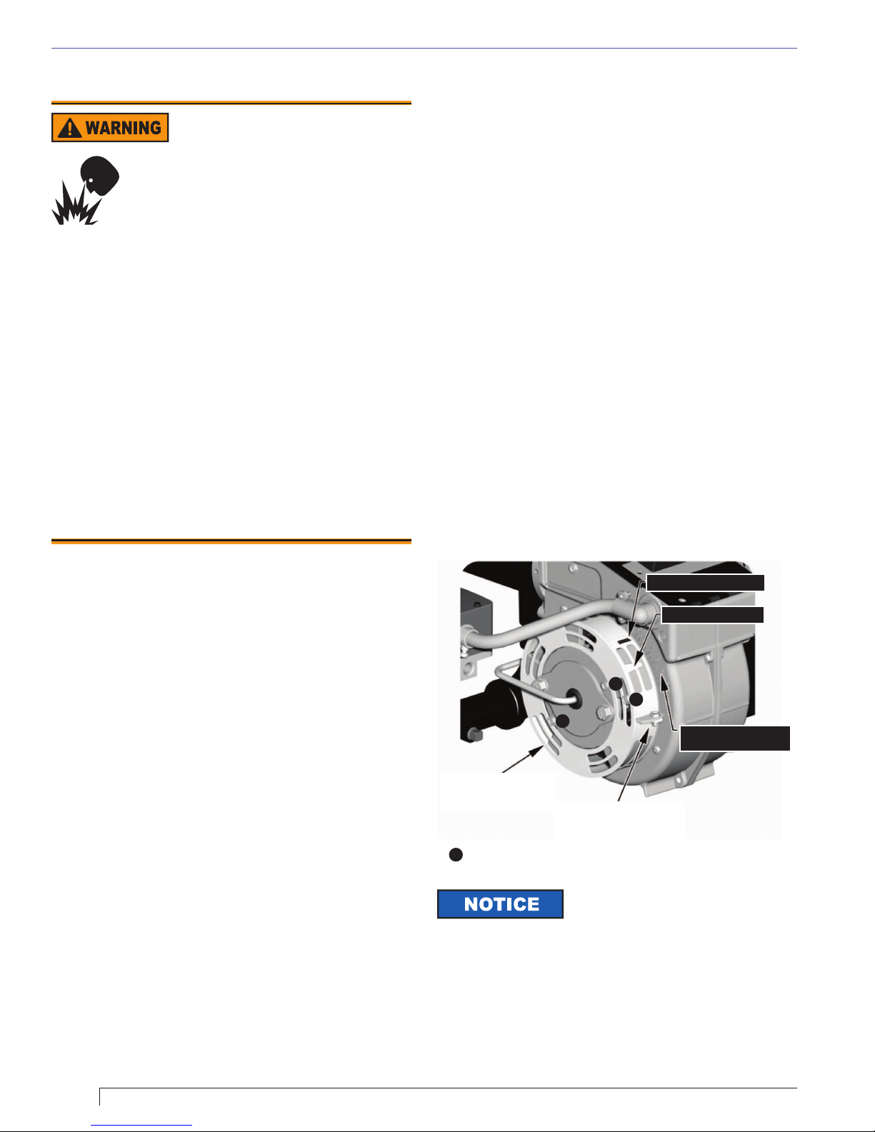
Figure 11. Shutter and Band
ADJUSTMENT SCALE
(FOR SHUTTER AND BAND)
BAND INDICATOR MARK
SHUTTER INDICATOR
SHUTTER
(for low rate adjustments)
adjust this with band fully
CLOSED AIR BAND
(for high rate adjustments)
adjust this with shutter fully
OPEN
=
Tighten locking screws securely after adjustments have been made
◄
◄
◄
◄
The shutter and band both control
the amount of flow area available for
air inlet to the burner. The greater their combined flow area,
the higher the firing rate. The primary differences between
the two are their ease of adjustment and their total airflow
area. The shutter turns more easily and has a smaller net
flow area. As a result we have found the shutter to be better
suited for low rate adjustments, and the band better suited
for high rate adjustments. We recommend that at low rates
the band be left completely closed until the shutter has been
fully opened, and that for higher rates the shutter is left
completely open as the band is opened.


 User manual")


