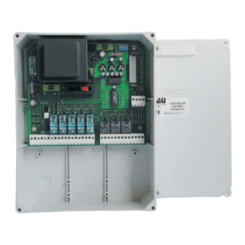
Böning AHD 903BS User manual

1
bugvs-e.mcd
BOWTHRUSTERCONTROLWITH
VARIABLEPITCH PROPELLER
AHD 903BS
13579
13579
2468
2468
11 13 15 17 19 21 23 25 27 29 31 33 35 37 39
11 13 15 17 19 21 23 25 27 29 31 33 35 37 39
10121416 18 20 22 24 26 28 30 32 34 36 38 40
10121416 18 20 22 24 26 28 30 32 34 36 38 40
40-poleribbon cable
40-poleribbon cable
14-poleribbon cable
14-poleribbon cable
pluggableon bothsides
pluggableon bothsides
Covering
Covering
pluggableon bothsides
pluggableon bothsides
12345678
12345678
Transferstation
Transferstation
Analog station AHD 903-15
Analog station AHD 903-15
Relaystation AHD903R
OutputunitAHD 903IP
Rail TS32 or35
Accelerator
Wing pt. Bridge Wing stb.
4wiresincl.powersupply
Actual-value-registration
Fordisplayatthe
controldesks
Rail TS32 or35
Impulselengthcontrolled magneticvalves
Development, manufacturing, service for shipping and industry
Böning Automationstechnologie GmbH & Co. KG • Am Steenöver 4 • D-27777 Ganderkesee
Phone: +49(0)4221 9475-0 • Fax: +49(0)4221 9475-22 • Internet: www.boening.com • E-Mail: [email protected]

2
Control for Bow Thruster with Adjustable Pitch Propeller
AHD 903BS 903bsi-e
Contents
Page
1. Construction 3
2. Control Units 3
3. Bow Thruster 4
4. Failure Report 4
5. Commissioning 4
Terminal Diagram 8
Dimensional Drawing 9
Technical Data 9

3
Control for Bow Thruster with Adjustable Pitch Propeller
AHD 903BS
1180-1i-e.DOC
1. Construction
The system for controlling a bow thruster with adjustable-pitch propeller consist of two units.
The operating unit for the three control units is located on the bridge, the control unit for
propeller adjustment at the bow thruster. Both units communicate serially with each other and
are connected over four wires (incl. power supply). They consist of similar analogue data
stations AHD 903-15. An additional relay module AHD 903R is used on the bridge and a
module AHD 903IP, as well as two further relays, are used for impulse length control on the
bow thruster side.
2. Control Units
The operating unit on the bridge receives the inputs from the main control unit, as well as
from two wing control units on port and starboard. The default angle for propeller adjustment
is reegistered and evaluated over a potentiometer (joystick with 0-positon in the middle).
After activation, the system can only be operated from the bridge control unit. Before starting
for propeller drive is enabled at the bow thruster side (relay K3), the selector switch for
operation has to be in position "bridge” and the potentiometer has to be in position “0” (micro-
contact). As long as these conditions are not fulfilled, the lamp „ready for operation“ at the
bridge control unit signalises this by slow flashing in a 1.5-seconds-cycle. Once the start
function is enabled, the flashing turns into permanent light.
Adjustment of the bow thruster angle is done over a 3-point after-running controller by
comparison of target (joystick) and actual value (controller at the bow thruster).
If, during operation, driving shall be continued from one of the wing control units, the selector
switch for operation at the main control unit has to be switched into the appropriate position
(port or starboard). Then, the takeover-button at the wing control unit has to be pushed, which
causes flashing of the lamp „ready for operation“. The real takeover happens when the default
target value at the wing control unit (joystick position) is the same as the presently active
actual value. As long as this is not the case, operation of the bow thruster will be continued
from the bridge control unit, even if the selector switch for operation is in starboard- or port-
position. If the conditions for takeover at the wing control unit are fulfilled, the flashing of the
lamp „ready for operation“ turns into permanent light and the system is now operated from the
wing. If there is no synchronisation between target and actual value within ten minutes, the
flashing lamp „ready for operation“ at the wing control unit goes out again. In this case,
takeover would have to be repeated.
The re-transmission of the command from wing to bridge is done in the same way as
described before. The selector switch for operation has to be switched into position
“bridge/main control unit” and the takeover-button has to be pushed. For correct takeover, the
default target value must be equal to the actual value, too.
Each control unit has an actual value indication for the actual propeller angle. For safety
reasons, this indication is led separate from the system and activated directly by the actual-
value-controller at the bow thruster.

4
3. Bow Thruster
On the bow thruster side, the target value default settings are received serially by the
operating unit and the relevant proportional-magnet-valves are activated via a servo control
(impulse length control). For return information, the actual value of the propeller angle is
registered analogously and then evaluated.
If target and actual position are too far from each other, the relevant transistor output
(increase or decrease angle) connects through completely. The actual value now tracks the
target value and gets close to it. Within this close-up range, the two proportional solenoid
valves are activated by the impulse durations. Therefore, there should always be a stabile
condition when the system is deactivated (actual value = target value).
The close-up range must be regarded as positive and negative offset around the actual value.
The default value for it corresponds to a certain angle which can be adjusted over 6 DIP-
switches on the circuit board in the terminal box. At this, two criteria have to be considered:
a) The smaller the close-up range can be chosen, the more precisely the actual value is
adjusted to the target value.
b) On the other hand, the value should be chosen high enough to allow balancing (in the
relevant system) of deviations caused by oil leakages, within the range of the impulse length
activation or within the close-up range.
The solenoid valves do not open before a minimum current is reached. The minimum current
is usually 20% of the rated current. This minimum current can be adjusted with a special DIP-
switch.
a) Level 1 = 16% minimum current, which means that the valve is still closed at the start of
the control range.
b) Level 2 = 24% minimum current, which means that the valve is always opened a little bit at
the start of the control range.
The solenoid valves are only activated in connection with enabled start function. The
conditions for enabled start function are as described above.
4. Failure Report
Relay K4 serves for failure report at the bridge side, as well as at the bow thruster side. An
open contact signalises a failure, missing configuration (see Setup) or wire breakage and can
thus be evanluated or indicated correspondingly. Additionally, in case of failure, the start
release is cancelled and the solenoid valves are switched idle.
5. Commissioning
In order to make the system ready for operation, it has to be programmed via the integrated
adjustment software. If programming has not yet been done, the system can not work. In this
case, the failure-relay K4 is activated after switching on of the device and the lamp “ready for
operation” on the bridge flashes in a 5-seconds-cycle; 1 second on, 4 seconds off. Thus, the
user is requested optically to do the programming.

5
On request, the system can be pre-configured ex works. Thus, the system is ready for
operation immediately after switching on, but this is only reasonable, if the exact adjustment
values are known (e. g. for spare-parts, as far as the adjustment values had been taken
down).
During programming, the target- and actual-value-positions of the controllers are co-ordinated
with eachother. For this purpose, the relevant limiting positions of the adjustable pitch
propeller have to be adjusted and the corresponding positions of the controllers have to be
stored durably. Please program as follows:
1. Switch off power supply of the device. To activate the programming mode, terminals
37 and 38 of the unit, which is installed on the bridge, have to be connected over a
jumper.
2. Now switch on again the power supply. The lamp “ready for operation” in the bridge
control unit should flash rapidly with two flashes per minute. This signalises the
activated programming mode.
3. The selector switch for operation from the bridge control unit is now turned into
position “port” to adjust the first limiting position. “Port” is now the value for max.
negative propeller angle.
4. Correspondingly, now the max. negative propeller angle is directly adjusted over
manual or emergency control of the bow thruster.
5. Then, the target value controllers (joysticks) of all three control units are switched into
position „max. negative propeller angle“ (lowest position).
6. After checking the three previous instructions again, now, the relevant controller
positions for this limiting position can be stored durably. For this purpose, the
takeover-button in the bridge control unit has to be pushed for app. 1 sec. After
disengaging this button, the lamp “ready for operation” shows permanent light for app.
2 sec. in order to acknowledge programming optically.
7. For adjustment of the second limiting position, the selector switch for operation is
switched into position “starboard” (Stb. is now the value for max. positive propeller
angle).
8. Now the max. positive propeller angle is adjusted over manual or emergency control.
9. The controllers (joysticks) of the three control units are then adjusted into the
corresponding position “max. positive propeller angle” (highest position).
10. The programming of this limiting position is now done as described under 6. (pushing
of the takeover-button for app. 1 sec.).
11. Finally, the zero-position is adjusted. For this purpose, the selector switch for
operation is switched into position “bridge” (bridge is now the value for zero-position).
12. Now, the zero-position (angle = zero) is adjusted over manual or emergency control.
13. The potentiometers (joysticks) of the three control units are adjusted into positon
“angle zero”. While doing this, it has to be monitored, if the micro-switch “position

6
zero”, which is mechanically linked with the bridge control, really closes, as otherwise
the zero-position can not be adjusted.
14. The programming of the zero-position is now also done as described under 6.
(pushing of the takeover-button for app. 1 sec.). If there is no optic acknowledgement
(2 sec. permanent light), the micro-switch “position zero” at the controller of the bridge
control unit is not closed. Please check again.
15. The jumper between terminals 37 and 38 is now removed to quit the programming
mode. The power supply can remain switched on during this procedure. In case of
correct programming, normal operation starts immediately.
After every programming step and after every activation, the installed software checks the
conclusiveness of all programmed adjusting values. If they are not conclusive (e. g. min.-
value higher than max.-value), the failure-relay K4 is activated and the lamp „ready for
operation“ flashes in a 5-second-cycle; 1 sec. on, 4 sec. off.
Possible mistakes are, e. g., mix-up of the exterior controller connections (at max. positive
propeller angle, the voltage at the slider has to be higher than in zero-position) or a wrong
position of the selector switch (operation), whose labelling has a different meaning during
programming. Anyway, in case of such a mistake, the whole programming procedure has to
be repeated. The same applies, if there is a power failure during the programming phase.
If necessary, a new adjustment can be done later at any time. Here, it is also possible to only
program single positions, e. g. only position angle zero --> follow instructions 1, 2, 11 to 15.
If the stored adjustment parameters shall be taken down, the installed EEPROM has to be
removed for a short time and has to be read with a separate programming device.
DIP-Switch on Additional Module AHD 903IP
The size of the close-up range can be specified qualitatively as binary value with 6 DIP-
switches in a range of 0-63. The value is proportional to the adjustable angle and has to be
adjusted iteratively depending on the overall order. The close-up range is adjusted on the
value 32 at delivery.
1 2 3 4 5 6 7 8
1
1
2
2
3
3
4
S
W
1
S
W
2
AnsichtaufdieAusgabeein-
h
e
i
t
A
H
D
9
0
3
I
P
v
o
n
o
b
e
n
ohne Abdeckung
DIP-SchalterSW1,SW2
zurEinstellung desNah-
bereichs
View of the output-unit
AHD 903IP from
above without cover.
Dip-switch SW1, SW2
for adjustment of
minimum range

7
For the DIP-switches applies: ON = binary low
OFF = binary high
SW1 – switch 2 corresponds to the most significant byte
(value = 32)...
SW2 – switch 4 corresponds to the least significant byte
(value = 1)
Example: SW1-S2(32) = OFF Byte = High Proportion of total value = 32
SW1-S3(16) = ON Byte = Low No proportion
SW2-S1(8) = OFF Byte = High Proportion of total value = 8
SW2-S2(4) = OFF Byte = High Proportion of total value = 4
SW2-S3(2) = ON Byte = low No proportion
SW2-S4(1) = OFF Byte = High Proportion of total value = 1
Therefore, the total value of the close-up range is 45.
The min. current for the proportional solenoid valves is adjusted with the SW 1 - switch 1:
ON Imin = 16% of target current
OFF Imin = 24% of target current

8
1180-10e.MCD
AHD 903-15 AHD 903-15
+-
RibboncableRibbon cable
1234567891011 121314 151617 181920 2122 23 2425 26 12345678910 111213 1415 16 17 18 192021 222324 25 262728 293031 323334 353637 383940 27 28 29 30 3132 333435 36 37 38 39 40
1234567812345678
K1K2K3K3
AHD 903RAHD 903IP
K4K4
Ribbon cableRibbon cable
Bb.
Br.
Stb.
Failure(NC)
(DIMMER)
+-
24VDC
24VDC
Lamptest
Lamptest
Lamptest
Inprogr.mode
bridge
0-Position
Nom.position
Nom.position
Nom.position
Takeover
Takeover
Takeover
Takeover
Takeover
Takeover
Operation/
Operation/
Operation/
BRIDGEBB.Wing PanelSTB.Wing Panel
Adjustableangle
IMPORTANT:All potentiometers=2... 2.5kOhm
actualvalue
Atmax.positiveangle,the voltage atall potentio-
meter-slidershastobe app.10 ...12 Volts!
Act.value
Indication
Startrelease
Failure(NC)
Adjustablepitch
propellercontrol
1180-10e
anglesmaller
anglelarger
24VDC
+-
Powertransistorsopticallydeconnected
perm.load:
5Ashort-term(5s)
1.5Apermanentvoltage
ControlUnits
Bowthruster
serialconnection
pulselength-
output

9
13579
2468
11 13 15 17 1921 23 2527 29 31 33 3537 39
1012 14 16 18 20 22 24 2628 30 32 34 3638 40
40-poleribbon cable 14-poleribbon cable
pluggablefrombothsidesCovering pluggablefrombothsides
12345678
Longholediameter.5,5
357
380
903ver-e.MCD
903ver-e
switching station Analog DataStation AHD 903-15 RelayStation AHD 903R
orOutputUnitAHD 903IP
RailTS35 or35
110
deep
60
12345678
11 22 33 4
SW1SW2ViewofOutputUnit
AHD 903IPfromabove
withoutcovering.
DIP-switchSW1,SW2
foradjustmentofthe near-
limiting-value-range
ControlforbowthrusterAHD 903BS
withadjustablepitchpropeller
TECHNICALDATA:
Powersupply
Powercons.ofelectronics
Perm.load ofrelaycontacts
Permload oftransistors
Serialinterface
Inputs
Perm.rel.airhumidity
Weight
:24VDC +/-25%
:app.0.15A
:1A
:1.5Apermanentcurrent, 5Ashort-term(5s)
1xTTYbidirectional(currentloop)
15 xanalog/binary
:99%
:1.5kg
:
:
Table of contents
Popular Control Unit manuals by other brands

Xsens
Xsens MTi 1 Series Integration manual
SMC Networks
SMC Networks VHS20 Series Operation manual
olympia electronics
olympia electronics i-OLEG LumiGate GR-7610/V2 manual

Eaton
Eaton PM3 Instruction leaflet

Honeywell
Honeywell PEHA 940 AMA Installation and operating instructions

Novoferm
Novoferm TAD MS Mounting and operating instructions
