Xsens MTi 1 Series Use and care manual

Xsens Technologies B.V.
Xsens North America, Inc.
Pantheon 6a
P.O. Box 559
7500 AN Enschede
The Netherlands
phone +31 (0)88 973 67 00
fax +31 (0)88 973 67 01
e-mail info@xsens.com
internet www.xsens.com
10557 Jefferson Blvd,
Suite C
CA-90232 Culver City
USA
phone 310-481-1800
fax 310-416-9044
e-mail info@xsens.com
internet www.xsens.com
Document MT1503P, Revision A, 5 Apr 2018
MTi 1-series
Hardware Integration Manual

www.xsens.com
ii
Document MT1503P.A
© Xsens Technologies B.V.
Hardware Integration Manual MTi 1-series
Revisions
Revision
Date
By
Changes
A
05 Apr 2018
RGI
Initial release
© 2005-2018, Xsens Technologies B.V. All rights reserved. Information in this document is subject to
change without notice. Xsens, MVN, MotionGrid, MTi, MTx and Awinda are registered trademarks or
trademarks of Xsens Technologies B.V. and/or its parent, subsidiaries and/or affiliates in The
Netherlands, the USA and/or other countries. All other trademarks are the property of their respective
owners.

www.xsens.com
iii
Document MT1503P.A
© Xsens Technologies B.V.
Hardware Integration Manual MTi 1-series
Table of Contents
1GENERAL INFORMATION ................................................................................................................... 1
2POWER SUPPLY ................................................................................................................................ 2
2.1 MAIN SUPPLY VOLTAGE (VDDIO) .......................................................................................................... 2
2.2 ANALOG SUPPLY VOLTAGE (VDDA) ........................................................................................................ 2
2.3 SINGLE POWER SUPPLY CONFIGURATION ................................................................................................... 2
2.4 POWER SUPPLY SPECIFICATIONS ............................................................................................................. 3
3INTERFACES ...................................................................................................................................... 4
3.1 PIN CONFIGURATION .......................................................................................................................... 4
3.2 COMMUNICATION TO HOST .................................................................................................................. 4
3.2.1 PSEL serial host communication interface selection ................................................................. 5
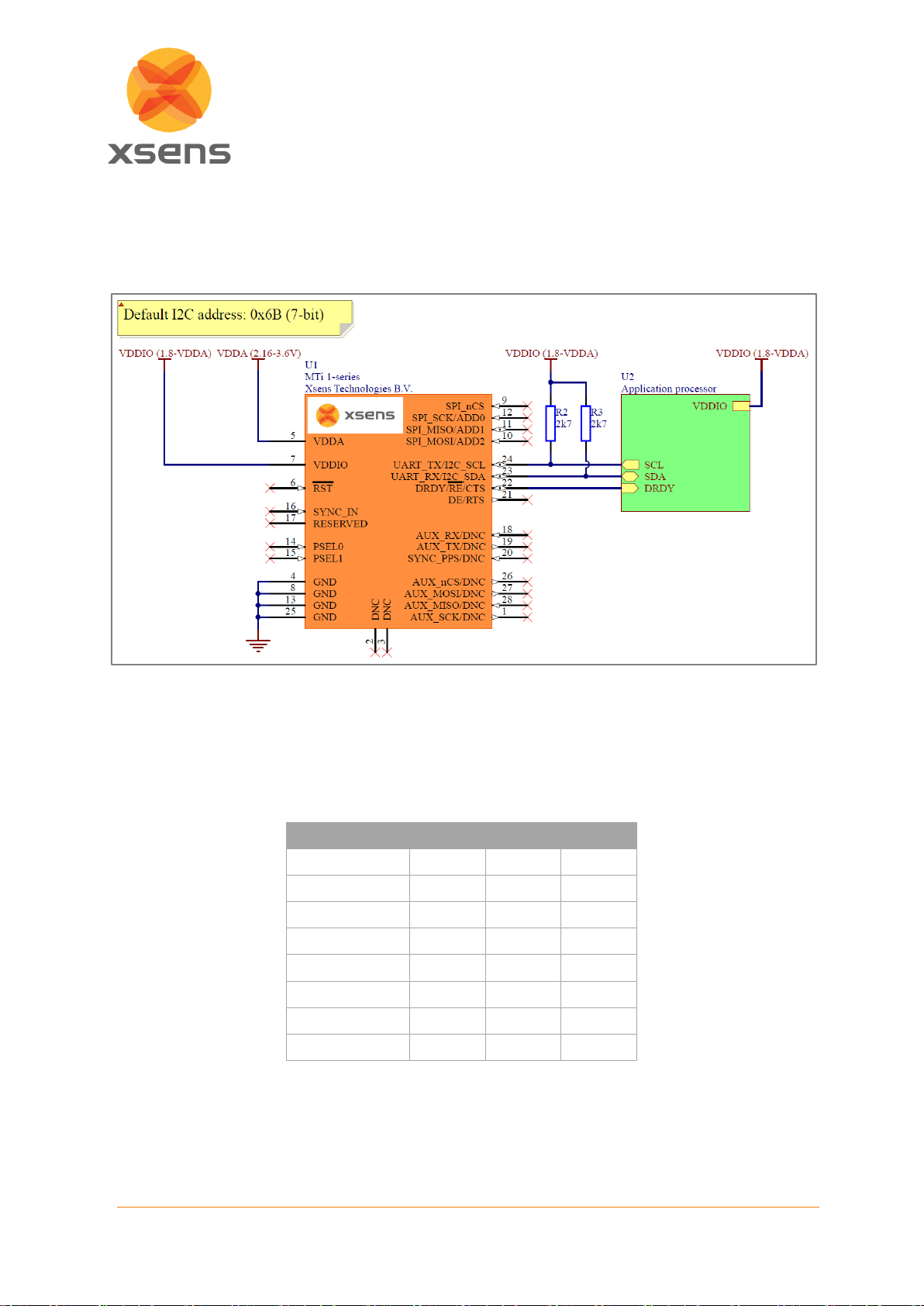
3.2.2 I2C....................................................................................................................................... 6
3.2.3 SPI....................................................................................................................................... 7
3.2.4 UART ................................................................................................................................... 7
3.3 GNSS RECEIVER AND BAROMETER INTERFACE............................................................................................. 8
3.4 I/O PINS ......................................................................................................................................... 9
3.4.1 Reset ................................................................................................................................... 9
3.4.2 SYNC_IN .............................................................................................................................. 9
3.5 DNC/RESERVED PINS....................................................................................................................... 9
4DESIGN........................................................................................................................................... 10
4.1 PCB LAYOUT.................................................................................................................................. 10
4.1.1 Frames of reference used in MTi 1-series .............................................................................. 10
4.1.2 Origin of measurements...................................................................................................... 11
4.2 MECHANICAL STRESS ........................................................................................................................ 11
4.2.1 Pushbutton contacts ........................................................................................................... 11
4.2.2 Anchor points..................................................................................................................... 12
4.2.3 Vibrations .......................................................................................................................... 13
4.2.4 Heat .................................................................................................................................. 13
4.2.5 Sockets .............................................................................................................................. 13
4.3 MAGNETOMETER ............................................................................................................................ 13
4.3.1 Ferromagnetic materials ..................................................................................................... 13
4.3.2 High currents ..................................................................................................................... 13
4.4 FOOTPRINT.................................................................................................................................... 14
5PACKAGING .................................................................................................................................... 15
5.1 TRAY PACKAGING INFORMATION .......................................................................................................... 15
5.2 REEL PACKAGING INFORMATION........................................................................................................... 16
5.3 PACKAGE DRAWING.......................................................................................................................... 17
6HANDLING...................................................................................................................................... 18
6.1 REFLOW SPECIFICATION ..................................................................................................................... 18
6.2 ULTRASONIC PROCESSES .................................................................................................................... 18
6.3 ELECTROSTATIC DISCHARGE (ESD)........................................................................................................ 19

www.xsens.com
iv
Document MT1503P.A
© Xsens Technologies B.V.
Hardware Integration Manual MTi 1-series
List of Tables
Table 1: MTi 1-series latest generation ........................................................................................................ 1
Table 2: MTi 1-series previous generation .................................................................................................... 1
Table 3: Maximum operating voltage ratings................................................................................................ 3
Table 4: Host communication interfaces specifications.................................................................................. 4
Table 5: Serial host interface selection ......................................................................................................... 5
Table 6: List of I2C addresses ....................................................................................................................... 6
Table 7: GNSS receiver interface specifications............................................................................................. 8
Table 8: I/O interface specifications............................................................................................................. 9
Table 9: MTi 1-series module generations .................................................................................................. 17
List of Figures
Figure 1: External components single supply (I2C interface) ........................................................................... 2
Figure 2: Pin configuration of the MTi 1-series module (top view).................................................................. 4
Figure 3: External components (I2C interface)............................................................................................... 6
Figure 4: Connections (SPI interface) ........................................................................................................... 7
Figure 5: Connections (UART interface full-duplex) ....................................................................................... 7
Figure 6: Connections (GNSS interface) ........................................................................................................ 8
Figure 7: Layout example .......................................................................................................................... 10
Figure 8: Default sensor fixed coordinate system for the MTi 1-series module .............................................. 10
Figure 9: Location origin of measurements................................................................................................. 11
Figure 10: High mechanical stress in diagonal crossover between anchor points ........................................... 12
Figure 11: Reducing anchor points to reduce overall stress in the PCB.......................................................... 12
Figure 12: Keeping the MTi 1-series module away from high mechanical stress areas.................................... 12
Figure 13: Recommended MTi 1-series module footprint ............................................................................ 14
Figure 14: MTi 1-series v1.1 dimensions and sensor locations...................................................................... 17
Figure 15: MTi 1-series v2.0 dimensions and sensor locations...................................................................... 17
Figure 16: Location PCB number on MTi 1-series module (bottom view) ...................................................... 17
Figure 17: Reflow classification profile (not to scale) ................................................................................... 18

www.xsens.com
1
Document MT1503P.A
© Xsens Technologies B.V.
Hardware Integration Manual MTi 1-series
1 General information
This document provides hardware design instructions for the MTi 1-series module. The MTi 1-series
module is a fully functional, self-contained module that is easy to design-in with limited external hardware
components to be added. The MTi 1-series module can be connected to a host through I2C, SPI or
UART interfaces.
Section 2 shows recommendations for power supplies for the 1-series. Section 3 provides information
about the different communication protocols that can be used, and section 4 describes some general
layout considerations. The last two sections provide information about packaging and handling.
The following symbols are used in this document to highlight important information:
A warning symbol indicates actions that could damage the module.
This document applies to the following products:
Table 1: MTi 1-series latest generation
Product name
Type number
Hardware version1
PCB number2
MTi-1
MTi-1T/R
≥ 2.0
≥ SM171223
MTi-2
MTi-2T/R
≥ 2.0
≥ SM171223
MTi-3
MTi-3T/R
≥ 2.0
≥ SM171223
MTi-7
MTi-7T/R
≥ 2.0
≥ SM171223
This document also applies for previous generations, unless noted otherwise.
Table 2: MTi 1-series previous generation
Product name
Type number
Hardware version
PCB number
MTi-1-8A7G6
MTi-1-8A7G6T/R
≤ 1.1
≤ SM141111
MTi-2-8A7G6
MTi-2-8A7G6T/R
≤ 1.1
≤ SM141111
MTi-3-8A7G6
MTi-3-8A7G6T/R
≤ 1.1
≤ SM141111
1
This number can be found on the packaging label (see Sections 5.1 and 5.2).
2
This number can be found on the bottom side of the MTi 1-series module (see Section 5.3).

www.xsens.com
2
Document MT1503P.A
© Xsens Technologies B.V.
Hardware Integration Manual MTi 1-series
2 Power supply
The MTi 1-series module has two supply pins: VDDA and VDDIO. They can be supplied
independently or tied together to adapt various concepts, depending on the intended application. The
different supply voltages are explained in the following subsections.
2.1 Main supply voltage (VDDIO)
The VDDIO pin is the main supply of the MTi 1-series module. This pin is connected to all the digital
IO’s, and powers the processor on the MTi 1-series module. Section 2.4 shows the acceptable range of
VDDIO. For the most power efficient implementation, the VDDIO pin should be connected to a 1.8 V
power supply.
2.2 Analog supply voltage (VDDA)
The VDDA pin of the MTi 1-series module is connected to all the power supply pins of the sensing
elements that are on the MTi 1-series module. There is no low-dropout regulator (LDO) on the
MTi 1-series. Section 2.4 shows the acceptable range of VDDA. To get the best sensor performance, it
is important that the VDDA pin is supplied by a power supply with a maximum ripple of 50 mVpp.
2.3 Single power supply configuration
The MTi 1-series VDDA and VDDIO supply pins can be connected to the same power supply. When the
MTi 1-series is supplied with a single power supply source, it is strongly recommended to decouple the
VDDA and VDDIO supply pins, for example with a resistor, for the best sensor performance (see Figure
1). This way the digital circuitry will not influence the analogue sensing part. Considering the minimum
operating voltage for VDDA, the single supply voltage VDD should be at least 2.2 V, due to the voltage
drop over R1.
Figure 1: External components single supply (I2C interface)

www.xsens.com
3
Document MT1503P.A
© Xsens Technologies B.V.
Hardware Integration Manual MTi 1-series
2.4 Power supply specifications
Table 3 shows the maximum operating voltage ratings of the MTi 1-series. Exposure to any voltage
beyond maximum operating voltage rating condition for extended periods may affect device reliability
and lifetime.
Table 3: Maximum operating voltage ratings
Min
Max
Unit
VDDA
2.16
3.63
V
VDDA ripple
50
mVpp
VDDIO
1.8
VDDA + 0.1
V
3
Previous generation version ≤1.1, VDDA max: 3.45V

www.xsens.com
4
Document MT1503P.A
© Xsens Technologies B.V.
Hardware Integration Manual MTi 1-series
3 Interfaces
3.1 Pin Configuration
Figure 2 shows the pin configuration of the MTi 1-series module. Pin 18, 19 and 20 are only used on the
MTi-7, for MTi-1/2/3 these pins need not be connected (DNC).
Figure 2: Pin configuration of the MTi 1-series module (top view)
3.2 Communication to host
The MTi 1-series modules are designed to be used as peripheral devices in embedded systems. The
MTi 1-series modules support inter-integrated circuit (I2C), serial peripheral interface (SPI) and universal
asynchronous receiver/transmitter (UART) protocols for the communication between the MTi 1-series
module and host CPU. The I2C and SPI protocols are well suited for communication between integrated
circuits and on-board peripherals. To select the correct communication interface, PSEL1 and PSEL0
should be configured accordingly (see section 3.2.1). For interface specifications, see Table 4.
Table 4: Host communication interfaces specifications
Interface
Min
Typ
Max
Units
I2C
Host I2C Interface Speed
400
kHz
SPI
Host SPI Interface Speed
2
MHz
Clock Duty Cycle
30
50
70
%
UART
Baud Rates
921.6
4000
kbps

www.xsens.com
5
Document MT1503P.A
© Xsens Technologies B.V.
Hardware Integration Manual MTi 1-series
3.2.1 PSEL serial host communication interface selection
The MTi 1-series modules has four modes of peripheral interfacing. Only one mode can be used at a
time and this is determined by the state of peripheral selection pins PSEL0 and PSEL1 at start up. Table
5 specifies how the PSEL lines select the peripheral interface. Note that the module has internal pull-ups
(30 kΩ – 50 kΩ). Not connecting PSEL results in a value of 1, connecting PSEL to GND results in a
value of 0.
Table 5: Serial host interface selection
Interface
PSEL1
PSEL0
I2C
1
1
SPI
1
0
UART half-duplex
0
1
UART full-duplex
0
0

www.xsens.com
6
Document MT1503P.A
© Xsens Technologies B.V.
Hardware Integration Manual MTi 1-series
3.2.2 I2C
I2C is the default interface (when PSEL1 and PSEL0 pins are floating or connected to VDDIO). The I2C
SCL and SDA pins are open drain and therefore they need pull-up resistors to VDDIO (R2 and R3 in
Figure 3; typical value: 2.7 kΩ).
Figure 3: External components (I2C interface)
The MTi 1-series module acts as an I2CSlave. The I2C slave address is determined by the ADD0, ADD1
and ADD2 pins. These pins are pulled-up internally so when left unconnected the address selection
defaults to ADD[0..2] = 111. Table 6 shows a list of all possible I2C addresses.
Table 6: List of I2C addresses
I2C address
ADD2
ADD1
ADD0
0x1D
0
0
0
0x1E
0
0
1
0x28
0
1
0
0x29
0
1
1
0x68
1
0
0
0x69
1
0
1
0x6A
1
1
0
0x6B (default)
1
1
1

www.xsens.com
7
Document MT1503P.A
© Xsens Technologies B.V.
Hardware Integration Manual MTi 1-series
3.2.3 SPI
For the SPI interface, PSEL1 can be left floating or pulled-up to VDDIO and PSEL0 pin needs to be
connected to GND, as shown in Figure 4.
Figure 4: Connections (SPI interface)
3.2.4 UART
For the UART full-duplex interface, PSEL1 and PSEL0 pins needs to be connected to GND, as shown
in Figure 5. The UART full-duplex communications mode can be used without hardware flow control. In
this case the CTS line needs to be tied low (GND) to make the MTi 1-series transmit. For UART
half-duplex interface, PSEL1 needs to be connected to GND and PSEL0 pin must be left floating (see
Table 5).
Figure 5: Connections (UART interface full-duplex)

www.xsens.com
8
Document MT1503P.A
© Xsens Technologies B.V.
Hardware Integration Manual MTi 1-series
3.3 GNSS receiver and barometer interface
The MTi-7 variant of the MTi 1- series module family supports external inputs from a GNSS receiver like
the uBlox MAX-M8. For the GNSS receiver, the UART communication and PPS/TIMEPULSE pins of
the receiver need to be connected to the AUX_TX, AUX_RX and SYNC_PPS pins of the MTi-7 module.
See Figure 6 for schematic details and Table 7 for interface specifications.
Table 7: GNSS receiver interface specifications
Interface
Typ
Max
Units
UART
Baud Rates
115.2
2000
kbps
Besides the GNSS receiver, the MTi-7 also supports an external barometer like the BMP280. For the
barometer, the SPI pins need to be connected to the AUX_nCS, AUX_MOSI, AUX_MISO and
AUX_SCK pins of the MTi-7 module. See Figure 6 for schematic details.
Figure 6: Connections (GNSS interface)

www.xsens.com
9
Document MT1503P.A
© Xsens Technologies B.V.
Hardware Integration Manual MTi 1-series
3.4 I/O pins
The I/O interface specifications are listed in Table 8.
Table 8: I/O interface specifications
I/O interface
Symbol
Min
Max
Unit
Description
SYNC_IN
VIL
0.3 ·VDDIO
V
Input low voltage
VIH
0.45 ·VDDIO + 0.3
V
Input high voltage
VHYS
0.45 ·VDDIO + 0.3
V
Threshold hysteresis
voltage
nRST
VIL
0.3 ·VDDIO
V
Only drive momentarily
RPU
30
50
kΩ
Pull-up resistor
TP
20
µs
Generated reset pulse
duration
3.4.1 Reset
The reset pin is active low. Drive this pin with an open drain output or momentary (tactile) switch to GND.
During normal operation, this pin should be left floating, as this line is also used for internal resets. This
pin has an internal weak pull-up to VDDIO.
Do not connect the reset pin directly to VDDIO!
3.4.2 SYNC_IN
SYNC_IN pin accepts an external trigger, on which the MTi 1-series sends out the latest available data
message. The SYNC_IN pin is 5V tolerant and can be connected directly to an external device. Please
make sure that the MTi 1-series and the external device are connected to or have the same common
GND. Table 8 shows the electrical specifications.
3.5 DNC/RESERVED pins
These pins are reserved for future use.
Do not connect, leave pins floating!

www.xsens.com
10
Document MT1503P.A
© Xsens Technologies B.V.
Hardware Integration Manual MTi 1-series
4 Design
4.1 PCB layout
To prevent current flows that can influence the performance of the MTi 1-series, it is recommended to
remove all copper (planes) underneath the MTi 1-series as shown in Figure 7.
Figure 7: Layout example
4.1.1 Frames of reference used in MTi 1-series
The MTi 1-series module uses a right-handed coordinate system as the basis of the sensor frame.
Figure 8: Default sensor fixed coordinate system for the MTi 1-series module
Z
X
Y

www.xsens.com
11
Document MT1503P.A
© Xsens Technologies B.V.
Hardware Integration Manual MTi 1-series
4.1.2 Origin of measurements
The accelerometer determines the origin of measurements. Figure 9 shows the location of the
accelerometer of the MTi 1-series.
Figure 9: Location origin of measurements
4.2 Mechanical stress
In general, it is recommended to place the MTi 1-series module in an area on the PCB with minimal
mechanical stress. The following paragraphs show causes of mechanical stress and ways to reduce it.
4.2.1 Pushbutton contacts
Pushbuttons induce mechanical stress when used. Therefore, it is recommended to keep a reasonable
distance between a pushbutton and the MTi 1-series module.

www.xsens.com
12
Document MT1503P.A
© Xsens Technologies B.V.
Hardware Integration Manual MTi 1-series
4.2.2 Anchor points
Anchor points are usually a cause of mechanical torsional stress. The MTi 1-series module should not
be placed near an anchor point. Furthermore, since a plane is uniquely determined by three points, it is
recommended to affix the PCB with no more than three anchor points. More than three anchor points
over define the PCB plane and therefore induce mechanical stress. Figure 10 shows an example of a
PCB with four anchor points that gives a maximum stress in the centre of the diagonal crossover. Avoid
placing the MTi 1-series module in such an area.
Figure 10: High mechanical stress in diagonal crossover between anchor points
The best way to deal with the problem shown in Figure 10 is to remove one of the anchor points as
shown in Figure 11. This will reduce the overall stress in the PCB. If more anchor points are required
(e.g. in case of a large PCB) the MTi 1-series module should be moved to an area with minimal
mechanical stress, as shown in Figure 12.
Figure 11: Reducing anchor points to reduce overall stress in the PCB
Figure 12: Keeping the MTi 1-series module away from high mechanical stress areas

www.xsens.com
13
Document MT1503P.A
© Xsens Technologies B.V.
Hardware Integration Manual MTi 1-series
4.2.3 Vibrations
The MTi 1-series features an industry-leading signal processing pipeline (AttitudeEngineTM) which
rejects vibrations. For best results however, it is recommended that the MTi 1-series is mechanically
isolated from vibrations as much as possible. Especially in applications where vibrations are likely to
occur, the anchor points of the PCB that holds the MTi 1-series module should be dampened. The
required type of dampening varies from application to application.
4.2.4 Heat
Keep the MTi 1-series module away from heat sources. Thermal gradients can cause mechanical stress,
which can affect the sensor performance of the MTi 1-series.
4.2.5 Sockets
For best performance, it is best to solder the module directly onto a PCB by a solder reflow process.
When placed in a socket, the module may be subjected to mechanical stress by the springs in the
socket, which might result in deteriorated performance.
4.3 Magnetometer
The MTi 1-series uses a 3D magnetometer for measuring the geomagnetic field. This part is sensitive
to magnetic disturbances.
4.3.1 Ferromagnetic materials
Ferromagnetic materials can be magnetized and the magnetic behaviour can change during operation.
This behaviour will influence the measurements of the 3D magnetometer of the MTi 1-series.
Therefore, keep these ferromagnetic materials away from the MTi 1-series.
4.3.2 High currents
High current power lines on the PCB will introduce magnetic fields that will influence the measurements
of the 3D magnetometer of the MTi 1-series. Place high current power lines away from the MTi 1-series.
Example: a power line with a current of 100 mA at a distance of 10 mm, will introduce an error of 2 µT.

www.xsens.com
14
Document MT1503P.A
© Xsens Technologies B.V.
Hardware Integration Manual MTi 1-series
4.4 Footprint
The footprint of the MTi 1-series module is similar to a 28-lead Plastic Leaded Chip Carrier package
(JEDEC MO-047). Although it is recommended to solder the MTi 1-series module directly onto a PCB,
it can also be mounted in a compatible PLCC socket (e.g. 8428-21B1-RK of M3, as used on the MTi 1-
series Development Kit). When using a socket, make sure that it supports the maximum dimensions of
the MTi 1-series module as given in Section 5.3 (note the tolerance of ± 0.1 mm).
Figure 13: Recommended MTi 1-series module footprint

www.xsens.com
15
Document MT1503P.A
© Xsens Technologies B.V.
Hardware Integration Manual MTi 1-series
5 Packaging
The MTi 1-series module is shipped in trays with 20 modules or in reels with 250 modules.
5.1 Tray packaging information
Tray Dimensions (mm)
Tray packaging
information
Pin 1
Length
“X”
Width
“Y”
Height
“Z”
Pocket
X-Pitch
Pocket
Y-Pitch
Pocket
X-Y
Array
Qty/Tray
Qty/Box
322.60
135.90
7.62
14.65
16.00
12 x 12
20 units
20 units
Detail “A”
Marking
NOTES:
•All dimensions are in millimeters.
•Pictured tray representative only, actual tray may look different.
•The hardware version number is labeled SPEC REV on the TNR Label.

www.xsens.com
16
Document MT1503P.A
© Xsens Technologies B.V.
Hardware Integration Manual MTi 1-series
5.2 Reel packaging information
Carrier tape (mm)
Reels (mm)
Pin 1
Packing
Ao
Bo
Ko
W
Po
P1
P2
A
N
C
W3
Orientation
by quadrant
QTY/
Reel
12.6
-
12.8
12.6
-
12.8
2.9
-
3.10
23.70
-
24.30
3.90
-
4.10
15.90
-
16.10
1.90
-
2.10
177.80
55
12.80
-
13.50
23.90
-
27.40
1 & 2
250
NOTES:
•All dimensions are in millimeters, unless otherwise specified.
•The hardware version number is labeled SPEC REV on the TNR Label.
Other manuals for MTi 1 Series
2
This manual suits for next models
21
Table of contents
Other Xsens Control Unit manuals
Popular Control Unit manuals by other brands

WEG
WEG RUW-01 Installation, configuration and operations guide

Siemens
Siemens SINUMERIK 840D Function manual

Pilz
Pilz PIT es Set10u-5ns (AIDA) basic operating manual

RCF
RCF RDNET CONTROL 2 user manual

SSS Siedle
SSS Siedle FPM 611-01 Maintenance Operation Installation

Leonard
Leonard MEGATRON 270 INSTALLATION ADJUSTMENT SERVICE