B.O.B COZ User manual

OWNER’S
MANUAL
AK
Y
AK
Y
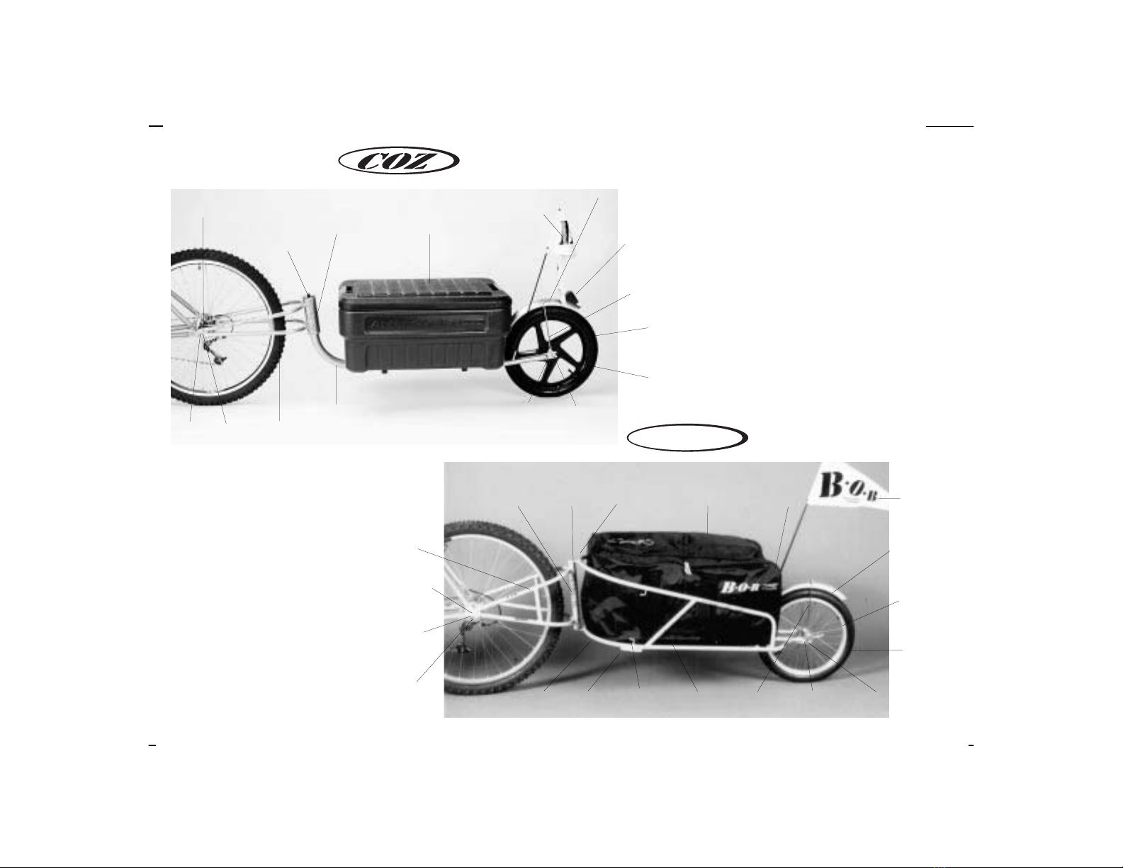
Fig. 1 Anatomy of the COZ and YAK trailers.
Boom
Tube
Fork
Pivot
Bolt
Fork
Fender
Reflector
Fender
Flag
Pin
Tire
Axle
Nut
Fender
Bracket
Wheel
Dropout
Action
Packer™
Hook
Rail
Tie
Rim
Skid
Pivot
Tube
Wheel Quick
Release
Upper
Rail
Cargo
Stop
Pivot
Plate
Pin Hook
Tire
Wheel
Dropout
Rim
Fork
Fender
Bracket
Flag
Lower
rail
B.O.B QR
B.O.B QR
AK
Y
YAK
Sak
Bungee
Hook
Pivot
Tube
Fender

TABLE OF CONTENTS
GENERAL INTRODUCTION / TIPS FOR USE . . . . . . . . . . . . . . . . . . . . . . . . . . . . . . . . . . . . . . .3
ASSEMBLY INSTRUCTIONS . . . . . . . . . . . . . . . . . . . . . . . . . . . . . . . . . . . . . . . . . . . . . . . . . . . .10
main frame . . . . . . . . . . . . . . . . . . . . . . . . . . . . . . . . . . . . . . . . . . . . . . . . . . . . . . . . .10
fender assembly . . . . . . . . . . . . . . . . . . . . . . . . . . . . . . . . . . . . . . . . . . . . . . . . . . . .11
wheel installation . . . . . . . . . . . . . . . . . . . . . . . . . . . . . . . . . . . . . . . . . . . . . . . . . . . .12
B.O.B Quick Release Installation . . . . . . . . . . . . . . . . . . . . . . . . . . . . . . . . . . . . . . . .17
trailer attachment . . . . . . . . . . . . . . . . . . . . . . . . . . . . . . . . . . . . . . . . . . . . . . . . . . . .21
MAINTENANCE . . . . . . . . . . . . . . . . . . . . . . . . . . . . . . . . . . . . . . . . . . . . . . . . . . . . . . . . . . . .25
WARRANTY . . . . . . . . . . . . . . . . . . . . . . . . . . . . . . . . . . . . . . . . . . . . . . . . . . . . . . . . . . . . . . .29
ADDITIONAL B.O.B PRODUCTS . . . . . . . . . . . . . . . . . . . . . . . . . . . . . . . . . . . . . . . . . . . . . . . .30
SPECIFICATIONS . . . . . . . . . . . . . . . . . . . . . . . . . . . . . . . . . . . . . . . . . . . . . . . . . . . . . . . . . . .32

2
PRE RIDE CHECK LIST
1. Check and tighten allen screws on the ends of the QR
before installation.
2. Check and tighten pivot allen screws on the COZ or
YAK before initial use. These screws must be tightened
against each other at the same time.
3. Sandwich fender with washers when attaching it to the
trailer with allen screw.
4. Check rear derailleur clearance after trailer is attached
before initial use.

CONGRATULATIONS on being the new owner of a B.O.B
trailer. We call it getting “B.O.B’d”. You are part of a grow-
ing movement in the bicycle world embracing lightweight,
hi-end, single wheel bicycle trailers. B.O.B is a company that
is committed to developing quality products which encour-
age a healthy, outdoor, car-free lifestyle. We make single-
wheeled cargo trailers, kid trailers, and strollers.
Before attempting to install or use your new trailer, read
these operating instructions completely to insure proper
assembly, installation, and operation. This manual covers
assembly, use, and maintenance instructions for both the
B.O.B COZ and YAK Bicycle Trailers. Many of the instructions
are the same for both models. In such cases the COZ and
YAK are referred to collectively as the “trailers”. In some
cases there are model specific differences. In cases of such
differences, model specific instructions are provided and are
so designated by model name. Thanks for getting B.O.B’d !!
IMPORTANT NOTICE
The trailers are designed to be attached to bicycles with
wheel diameters between 20 and 28 inches(includes 700c).
The dimensions of the tire appear as a raised surface on the
side walls. They will typically appear similar to the follow-
ing example: 26” x 1.9”. The first number refers to the
diameter and the second to the width. It is critical that your
wheels meet the diameter specifications listed above. If
they do not meet these specifications it is unsafe for you to
attach the trailers. If you have questions about your wheel
diameters or the compatibility of the trailers with your bicy-
cle, consult your bicycle dealer.
QUICK RELEASE
The trailers attach to your bicycle by means of a specially
designed quick release which inserts into the rear hub of
your bike. If your bike does not have a rear quick release,
the trailer will need to be attached with B.O.B Nutz. B.O.B
Nutz are special adapters for bicycles with solid axles. They
are made for axles with the following threading: 3/8 x 24
tpi, 3/8 x 26 tpi, 10 x 1, and 10.5 x 1 or 13/32 x 26 tpi (Sachs
and Sturmey Archer Internal Gear Hubs – I.G.H.) See Fig. 2.
DROP OUT SPACING
For the B.O.B quick release to safely work with your bicy-
cle, the overall dimension from outside to outside of your
bike frame’s rear wheel dropouts (overdrop dimension)
must fall within the following range:
Minimum Width 140 mm Maximum Width 156 mm
The correct way to measure your overdrop dimension is
3
AK
Y
shown and explained in the B.O.B Quick Release
Installation Section, item 2a., of the manual. If you are
uncertain of how to correctly measure the rear dropout out-
side to outside dimension, or whether your bicycle is com-
patible with the trailers, consult your bicycle dealer.
RIDING AND SAFETY TIPS
Pulling a B.O.B Trailer
Although the trailers have been designed to have as little
impact as possible on the handling and operation of your
bicycle, there are several points you need to be aware of
when pulling a trailer. The following information will famil-
iarize you with the peculiarities of pulling a trailer.
EXTREME ROTATION
In cases of extreme rotation of the trailer around the quick
release BOBBIN, in the counter clockwise direction, it is
possible for the fork to come in contact with the rear
derailleur mount as shown in Fig. 3. This contact can cause
damage to the derailleur mount, quick release, and retain-
ing pins and adversely affect the attachment of the trailer,
potentially resulting in the loss of control. It requires
approximately 20 degrees of counter clockwise rotation for
this condition to occur. This is beyond the intended scope
of use.
4
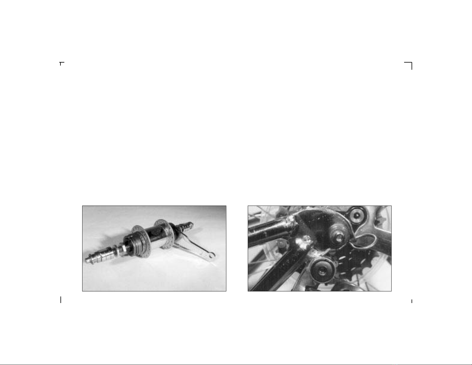
FIG. 2 BOB NUTZ solid axle adapters for bikes with solid axle hubs (includes Internal
Gear Hubs).
FIG. 3 Trailer in extreme counter-clockwise rotation showing contact between derailleur
pivot housing and trailer fork. AVOID this condition. If you believe this has occurred,
inspect your derailleur, QR, and pins for damage. Note: reversing the installation of the
QR (install from the drive side / right side of bike) helps eliminate this problem (Fig. 5a).

When the trailer is rotated in an extreme clockwise direc-
tion it is possible for the retaining pin on the derailleur side to
come in contact with the derailleur mount as shown in Fig. 4.
This contact can cause damage to the derailleur mount, quick
release, and retaining pins, and adversely affect the attach-
ment of the trailer, potentially resulting in the loss of control.
It requires approximately 90 degrees of clockwise rotation for
this condition to occur. This is beyond the intended scope of
use.
Whenever using the trailer, whether pulling or moving it,
be extremely careful to avoid these conditions. If you believe
this condition has occurred you should inspect your derailleur,
quick release, and pins to insure they are in good working
order. If you have questions about this, consult your dealer.
ATTACHMENT
Please refer to the Trailer Attachment section of the
Owner’s Manual for the correct installation of the quick
release and trailer. It is imperative that both the quick
release and trailer are installed correctly. Failure to do so
can result in accidents and injury. If, after reading the
instructions, you are uncertain about the correct operation
of the quick release and trailer attachment, consult your
bicycle dealer.
LENGTH AWARENESS
When towing the trailer, be very conscientious of the addi-
tional length you now have behind you! It can be very easy
to forget that you have anything back there and cut some-
one off. Get a feel for the proportions of your trailer by hav-
ing a friend ride your bike and trailer while you ride next to
and behind them. Use the flag provided as it tells everyone
(including cars) where you, are and more importantly, how
long you are. Please refer to the assembly section of the
Owner’s Manual for proper flag assembly and installation.
LOADING
It is very important that the trailer be loaded correctly to
insure safe operation. These guidelines should be observed
when loading:
Cargo Only - The trailers are designed as a cargo carrier.
DO NOT CARRY HUMANS OR ANIMALS.
5
FIG. 4 Trailer in extreme clockwise rotation showing contact between derailleur mount
and retaining pin. AVOID this condition. If you believe this has occurred, inspect your
derailleur, QR, and pins for damage

Cargo Weight Limit -
COZ: 50 POUNDS (23 KILOGRAMS)
YAK: 70 POUNDS (32 KILOGRAMS)
Be aware that the more weight you add to the trailer, the
more effect it will have on the handling of your bicycle.
When you start off with a load, get accustomed to how the
load affects the handling of your bicycle and adjust your
riding style accordingly.
Height Limit - The trailers are designed to keep the cargo’s
center of gravity as low as possible. When loading the trail-
er pay careful attention to keeping the load low as this will
effect the center of gravity and the handling of the bicycle.
The higher the load the greater the effect. With any new
load, become accustomed to how the load effects the han-
dling of your bicycle and adjust your riding style according-
ly.
COZ Note: The load height should never exceed the height
of the Action Packer box.
YAK Note: The load height should never exceed 18 inches
(46cm) from the trailer platform.
Securing Cargo - When loading the trailer, it is important
that all cargo be securely fastened as shifting loads may
adversely effect bicycle handling and result in loss of con-
trol. Additionally, cargo should never overhang from the
trailer. Also make certain there are no loose items such as
bag straps which can become caught on passing objects or
the spokes of either the bicycle or trailer.
The YAK comes with a 4 way bungee cord to assist you in
cargo retention. Depending on the nature of the load, it
may be necessary to use additional bungee cords or other
fasteners to properly secure your cargo.
BRAKING
Make sure your bike’s brakes are in top condition and prop-
erly adjusted. Marginally performing brakes will be inade-
quate for safe braking with the added load of a trailer.
Please refer to your bike’s Owner’s Manual or consult your
dealer for proper brake adjustment.
Braking Distance - Stopping distances will be longer when
pulling a trailer. Your bike must slow and stop the trailer,
which has no brakes of its own. The more weight in the
trailer, the longer the braking distance. Monitor your speed
for the trail, road, traffic conditions; and the load you are
carrying. Be especially careful to check your speed during
descents. Account for the additional braking distance
required to stop, and always use caution to maintain these
braking distances. We recommend that you practice stop-
ping your bike and trailer when first starting your ride to
get a feel for the time, distance, and brake lever force
required for making safe stops.
Wet Conditions - Most bicycles have a caliper braking sys-
tem which uses the side wall of the rim as the braking sur-
face. When it is wet, the sidewall becomes moist, reducing
friction and stopping power, and increases braking dis-
tances. When riding in wet conditions use extreme caution
and allow extra distance for braking.
6
VISIBILITY
Car drivers don’t expect bicycles to be pulling trailers.
Exercise additional caution to make sure you are seen.
Assume the trailer cannot be seen by motorists and other
traffic and adjust your riding style accordingly. When cross-
ing intersections, remember that your overall length has
increased. Allow additional time to safely cross. REMEM-
BER: the trailer is lower than you and your bike, and may
be obscured from motorist’s vision. The trailers come with a
visual safety flag which should always be used. CAUTION:
The use of the flag does not guarantee that others will see
you; ride with caution and awareness of what is behind
you. You may want to attach additional lights to the trailer,
such as a blinking red taillight.
NIGHT RIDING
The COZ comes with a fender reflector. The YAK comes
with wheel and fender reflectors. The reflectors must be
correctly installed and properly maintained for night riding.
Wheel reflector attachment is covered in the Reflector
Installation section and fender reflector attachment is cov-
ered under Fender Assembly.
Make certain the reflectors on your bicycle are properly
installed and in good working order. If you have any ques-
tions concerning this refer to your bike’s Owner’s Manual or
consult your dealer.
When riding at night, never ride without lights or
reflectors on both the bike and trailer. Contact your appro-
priate state government office to learn the legal lighting
requirements for your state.
STEERING
The trailers will effect the steering of your bicycle. Take the
following points into consideration and remember a bike
with a trailer attached will behave differently:
Tire pressure - It is CRITICAL that the rear tire of your
bicycle is inflated to the normal operating pressure
embossed on the circumference of the tire. Under-inflated
bike tires cause washout of the rear wheel and an unstable
riding condition for the bike and trailer. Tire pressure on
the trailers on the other hand, controls the amount of sus-
pension your cargo will enjoy. Always maintain tire pres-
sure for bicycle and trailer within the ranges suggested by
the tire manufacturer.
7
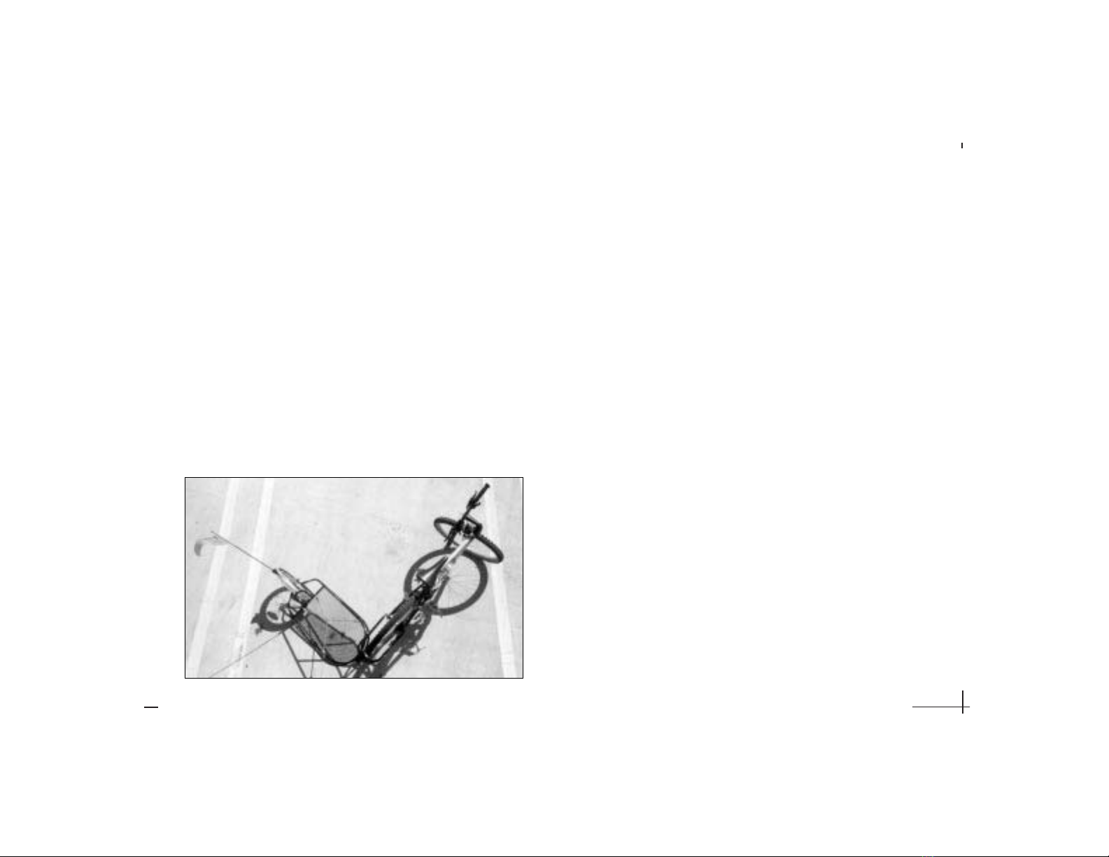
FIG. 5 Correct way to park bike and trailer. Note: correct direction to turn the
handlebars is towards the trailer. Trailer and handlebars are 90 degrees to bike.

Counterweight - Since the trailer is single wheeled and
attached to the rear axle, it will follow the side to side
movements of your bike. When standing to pedal, there is a
natural tendency to rock from side to side. When the trailer
is attached there will be added weight and the rocking
effect will be more pronounced. Because of this, it will take
more effort to stop the rocking of the trailer in one direction
and reverse it to the other. Be extremely careful not to
over-exaggerate this motion as extreme rocking will result
in rapid weight transfer and the possible loss of control.
PARKING
There are two ways to best park your bike and trailer:
a) A very simple way to park your bike and trailer is to
position it so it is parallel to a stable surface such as a
building, fence, or sign post. With the bike approximately
10 - 12 inches from the structure gradually lean the bicycle
over until it comes in contact with the structure. Check to
make certain the bike and trailer are stable.
NOTE: Always park your bike and trailer on level ground.
b) With your bike turned 90 degrees to the trailer and your
handlebars turned 90 degrees to the frame, the trailer will
stand up on its own. Just lean the bike and trailer over
while turning the bicycle handlebars perpendicular to the
bicycle frame in the direction of the trailer and – viola!!. See
Fig. 5. This feature works best when the trailer is loaded.
To “un-park”, have one hand on the handlebars, and
one hand on the seat. Walk forward with your bike, pulling
the seat towards you; the trailer will stabilize in the hori-
zontal position.
CAUTION: A small percentage of bike’s rear derailleurs are
positioned such that when parked, the fork of the YAK con-
tacts the derailleur pivot housing. Fig. 3 Verify with a
friend that there is adequate clearance before leaning the
bike and trailer completely over in park mode. Note: revers-
ing the installation of the QR (install from the drive
side/right side of bike) helps eliminate this problem. B.O.B
TRAILERS assumes no responsibility for bent derailleurs
that result from the owner neglecting to check for proper
clearance prior to utilizing “PARK MODE”. See Fig 5a.
8
FIG. 5a B.O.B QR installed from drive side/right side of bike.

YAK OFF ROAD RIDING SAFETY
Off Road Riding - The YAK is VERY off-road capable! The
COZ is not designed for off road use. When pulling the YAK
off-road it is important to observe the above points as all
these precautions also apply to safe dirt riding. Off road
riding, with its uneven terrain, loose surfaces, and unpre-
dictability will tend to magnify these concerns. With a trail-
er attached, your off road maneuverability will be reduced
and it is important to take this into consideration as you
negotiate obstacles and choose which trails to ride.
SECURITY
We recommend using a “U LOCK” or standard cable lock
system that is long enough to run through the rear triangle
of your bike and the fork of the trailer Fig. 1.
9
TAKE LONG
VACATIONS
WITH YOUR
FAMILY
ASSEMBLY INSTRUCTIONS
NOTE: B.O.B TRAILERS IS NOT RESPONSIBLE FOR INJURY,
DAMAGE, OR FAILURE THAT RESULTS FROM FAULTY
ASSEMBLY OR MAINTENANCE AFTER SHIPPING.
The following instructions explain how to correctly assem-
ble and attach your new trailer. If you do not have previous
experience with trailer and bicycle assembly and mainte-
nance, we recommend you have your trailer assembled and
attached by a professional bicycle dealer.
The following is a list of tools necessary to properly accom-
plish assembly, adjustment, and installation in accordance
with the assembly instructions:
ALLEN WRENCHES
ADJUSTABLE WRENCH
STANDARD SCREWDRIVER
PHILLIPS-HEAD SCREWDRIVER
METAL CUTTING SAW
METRIC DIE; 5mm x .8mm
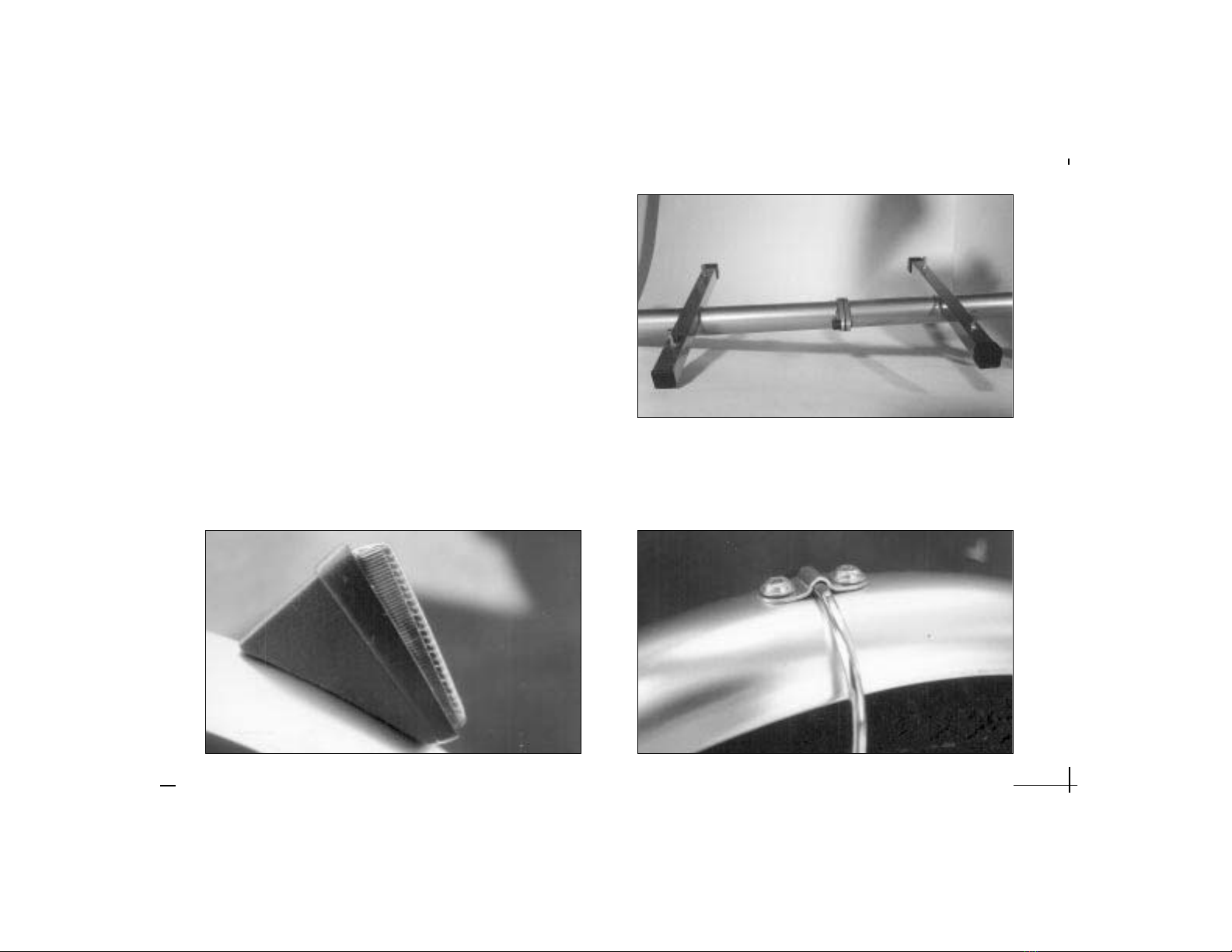
COZ FRAME ASSEMBLY
The COZ has a two piece frame which needs to be assem-
bled prior to attaching the Action Packer™ box. Start by
removing all items from the Action Packer™ and removing
packing materials. Next remove the nuts and bolts from the
flange on the “boom” tube as shown in Fig. 6. You will
need a 6mm Allen wrench.
Align the two flanges and install the bolt, lock washer,
and nut. When attaching the two halves make sure all the
box attachment studs are pointing upward as shown in Fig.
7. Securely tighten the flange nuts and bolts.
Remove the knobs and large area washers from the
cross braces. Place the Action Packer™ over the trailer
frame and align the 4 holes in the Action Packer™ with the
4 bolts in the cross braces. With the holes and bolts
aligned, set the box on the frame. Replace one of each of
the large area washers over the bolts and install the knobs.
Securely tighten the knobs.
10
FIG. 6 Flanges of “boom tube” and COZ flange bolts.
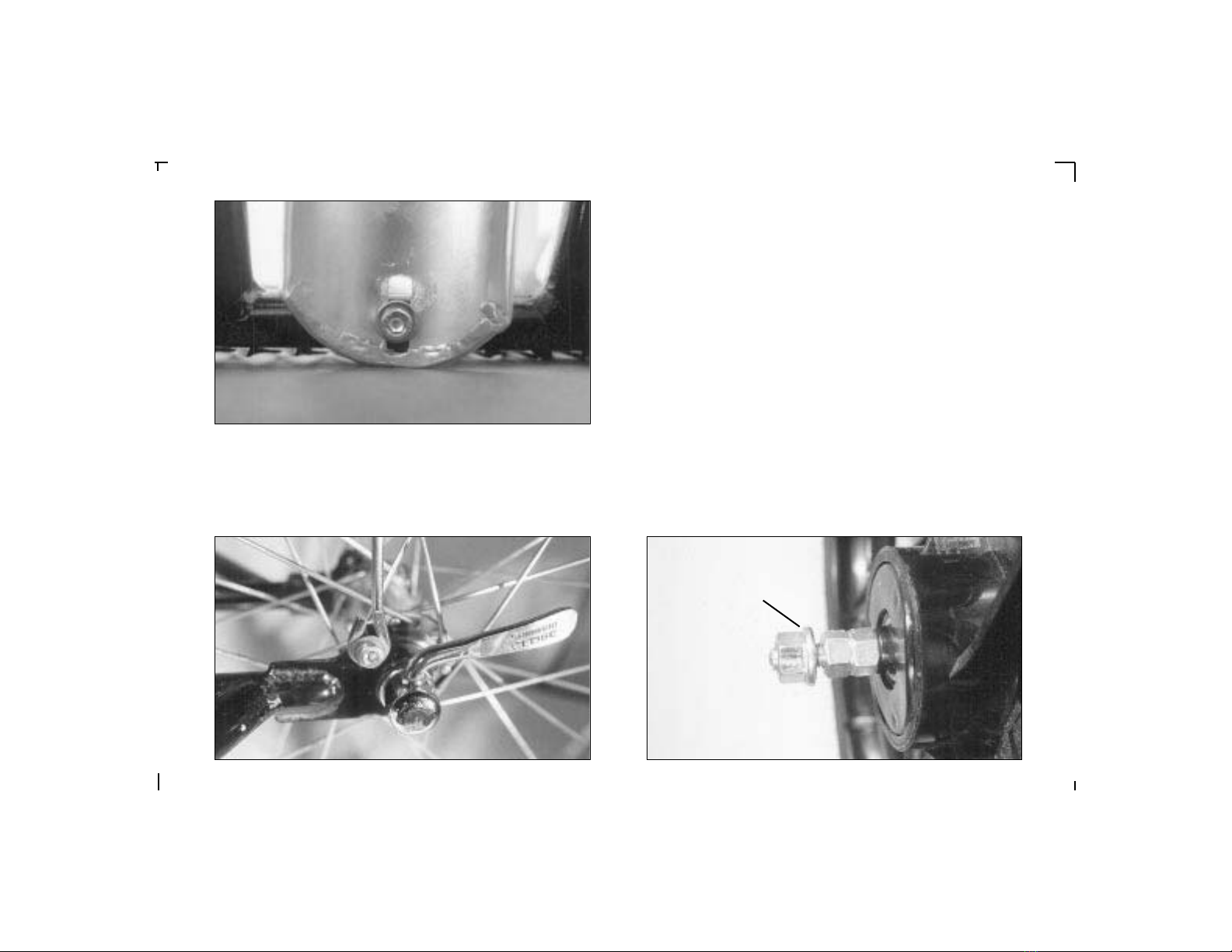
FENDER ASSEMBLY
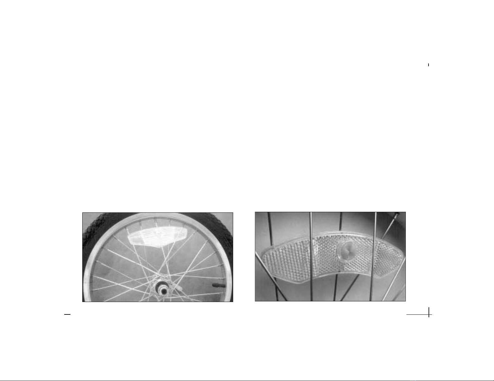
Fender Reflector Installation - The fender reflector attaches to
the rear portion of the fender. The reflector has a threaded stud
built into it. Attach the reflector to the fender by inserting the
stud into the upper hole and the plastic “alignment pin” into the
lower hole of the fender as shown in Fig. 8. Next, place the wash-
er over the portion of the stud extending through the underside of
the fender. Thread the nut on and tighten with an 8mm wrench.
Fender Bracket Attachment - First, attach the fender bracket to
the fender. Place the fender bracket in the center of the two holes
in the fender and align the mounting hardware with them as
shown in Fig. 9. Insert the screws from the outside of the fender
through the holes. Place the threaded backing plate on the inside
of the fender and tighten the screws using a screw driver.
11
FIG. 8 The correct orientation of the rear reflector on the fender. FIG. 9 Attach the fender bracket to the fender with mounting hardware as shown.
FIG. 7 COZ frame properly assembled with bolts pointing upward.
Fender Attachment - The fender attaches in three places.
Begin by removing the screw and washers from the for-
ward fender mount on the trailer frame. Attach the fender
to the trailer by inserting the bolt and washer through the
slot in the fender, then place the second washer behind it
(sandwiching the fender with washers) as shown in Fig. 10.
Tighten the bolt securely with a 4mm Allen wrench. Next,
attach the fender brackets to the left and right dropouts.
Insert the bolt through the washer and then through the
loop in the fender bracket as shown in Fig. 11. Align the
bolt with the eyelet in the dropout and tighten securely
with a 4mm Allen wrench.
COZ Wheel Installation - Fig. 12 shows the anatomy of a
nutted axle wheel. Study this diagram carefully so you
12
FIG. 10 Attachment of fender to trailer frame.
FIG. 11 Attachment of the fender to the dropout eyelet. FIG. 12 Anatomy of a nutted axle wheel.
Axle Nut with
Integrated
Washer
become familiar with the names of the various parts. This
will help you better understand the following instructions:
1) Remove the wheel from the box. Remove the plastic axle
caps from the axle of the wheel. Loosen the axle nuts with a
14mm wrench.
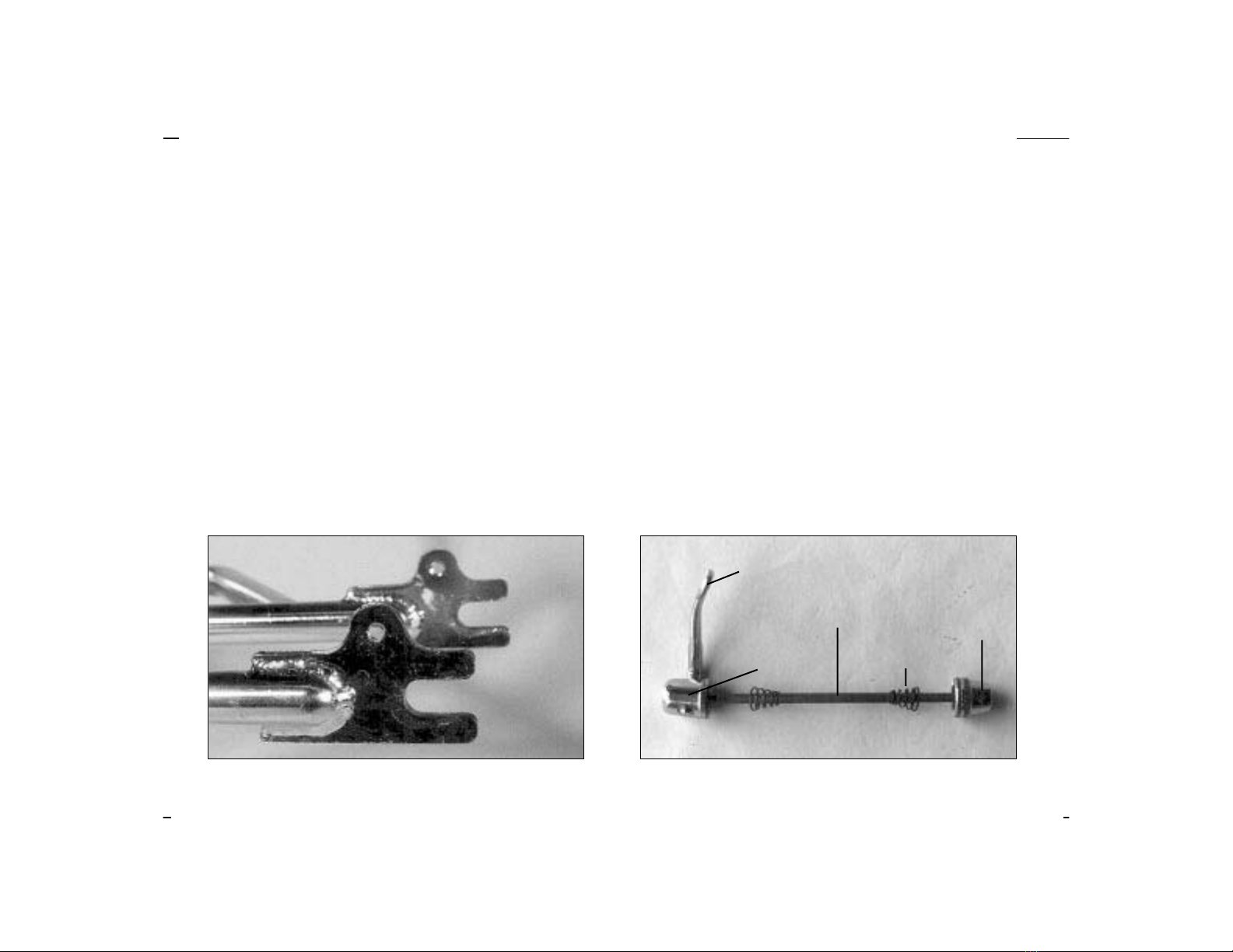
2) The trailer’s rear drop-out, Fig. 13, is slotted to receive the
axle of the wheel. With the trailer facing forward, slide the
wheel in the dropouts making sure the axle nuts are on the
outside of the dropouts.
3) Make sure the wheel is centered between the wheel stays.
4) Using two 14mm wrenches, tighten the axle nuts. It is
important that you tighten both nuts at the same time, tight-
ening them against one another.
After tightening the axle nuts, make sure the wheel is
still centered in between the wheel stays.
13
FIG. 13 Slotted rear dropout for axle insertion. FIG. 14 Anatomy of a quick release.
YAK Wheel Installation - Fig. 14 shows the anatomy of a
wheel quick release. Study this diagram carefully so you
become familiar with the names of the various parts. This
will help you better understand the following instructions:
1) Remove the wheel and quick release from the small
parts box. Remove the plastic axle caps from the axle of
the wheel.
2) Install the quick release in the wheel by first unscrew-
ing the adjusting nut, Fig. 14. To remove the adjusting nut,
turn it in a counter clockwise direction. With the nut and
one spring removed, insert the quick release through the
hole in the axle. Re-install the spring with the small end
towards the hub and thread the adjusting nut on by turn-
ing in a clockwise direction. At this point only tighten the
Adjusting
Nut
Quick Release
Lever
Cam Housing Conical Spring
Rod
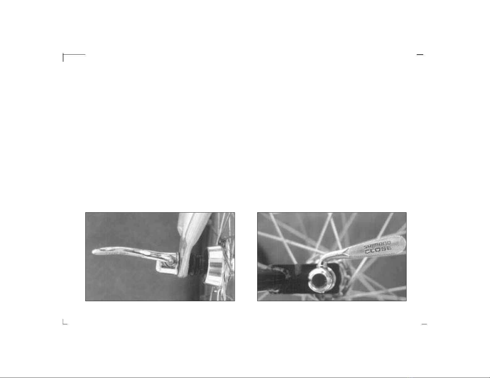
b. Turn the quick release lever towards the rear of the
trailer to the closed position, Fig. 16. The word CLOSE
should be clearly visible and the quick release lever should
be parallel to the wheel stay. It should require considerable
pressure to close the lever when it is properly adjusted and
tightened. If you do not feel this resistance, turn the quick
release lever back to the adjusting position, Fig. 15.
Tighten the adjusting nut by hand (it is not necessary to
use tools) one or two more turns in the clockwise direction.
Move the quick release lever toward the closed position,
Fig. 16. When properly adjusted, it requires 80-105
inch/pounds of pressure to move the lever to the fully
closed position.
NOTE: Follow all instructions exactly. If you are unsure how
to operate the quick release, consult your bicycle dealer.
14
FIG. 15 Quick release perpendicular to the trailer
nut three turns. Final adjustment will be made after the
wheel is installed in the trailer.
3) The trailer’s rear drop-out, Fig. 13, is slotted to receive the
axle of the wheel. With the trailer facing forward, slide the
wheel in the dropouts so that the quick release lever is on
the left hand side.
4) Make sure the wheel is centered between the wheel stays.
5) Be aware, the quick release is NOT a nut and bolt system.
It is a cam-activated tightening mechanism. Securely tighten
the quick release as follows:
a. Turn the quick release lever perpendicular (at a 90
degree angle) to the trailer, Fig. 15. Keep the quick release
lever from turning while you tighten the adjusting nut by
turning it in the clockwise direction until it comes in contact
with the trailer dropout.
FIG. 16 Quick release in closed position.
Tire pressure - It is CRITICAL that the rear tire of your bicycle
is inflated to the normal operating pressure embossed on the
sidewall of the tire. Under-inflated tires cause wash-out of the
rear wheel and an unstable riding condition for the bike and
trailer. Tire pressure for the wheel on your trailer is embossed
on the side wall of the tire. Tire pressure can be adjusted to
offer differing degrees of suspension and rolling resistance.
NOTE: Inflation pressure must always fall within the range
embossed on the sidewall of the tire.
COZ Reflector Installation - The COZ comes with wheel and
rear fender reflectors. The wheel reflector is pre-installed. The
installation of the rear fender reflector is covered under fender
assembly.
YAK Reflector Installation - The YAK comes with two types
of reflectors; a rear fender reflector and wheel reflectors. The
15
FIG. 18 Wheel reflector.FIG. 17 Wheel reflector correctly positioned.
installation of the rear fender reflector is covered under
fender assembly.
Every YAK comes with two spoke reflectors which
mount onto the spokes of the trailer wheel. It is best to
mount the reflectors 90 degrees from the valve stem Fig.
17. The reflectors should be installed by weaving them
through the spokes. The reflectors attach to the spoke with
the white slotted attachment “screw”, Fig. 18. Remove
attaching screw from reflector. Place reflector in position
between wheel spokes and centered on a spoke approxi-
mately 90 degrees from valve stem. Install screw, Fig. 18,
over spoke and into receiving hole of reflector. Using a
screwdriver, turn screw 90 degrees clockwise to lock
reflector in position. Repeat the above steps for the second
reflector to be installed opposite the position of the first

trailer by pulling it out of the trailer mounting bracket by
the lower half. To do this place your foot on the trailer to
weight the trailer and remove the flag by pulling gently
upward.
Front Fork Tightening
COZ - The front fork of the COZ pivots to the left and right.
The fork pivots around the “boom” tube. The fork is fas-
tened to the “boom” by a 5mm Allen bolt and lock washer,
Fig. 21. As a final check before attaching your trailer, make
sure the bolt is securely tightened. For reference, torque on
bolts should be: 44 inch pounds
YAK - The front fork of the YAK pivots to the left and right
between the upper and lower rail plates. The fork pivots
around a pivot rod attached to the pivot plates. The pivot
16
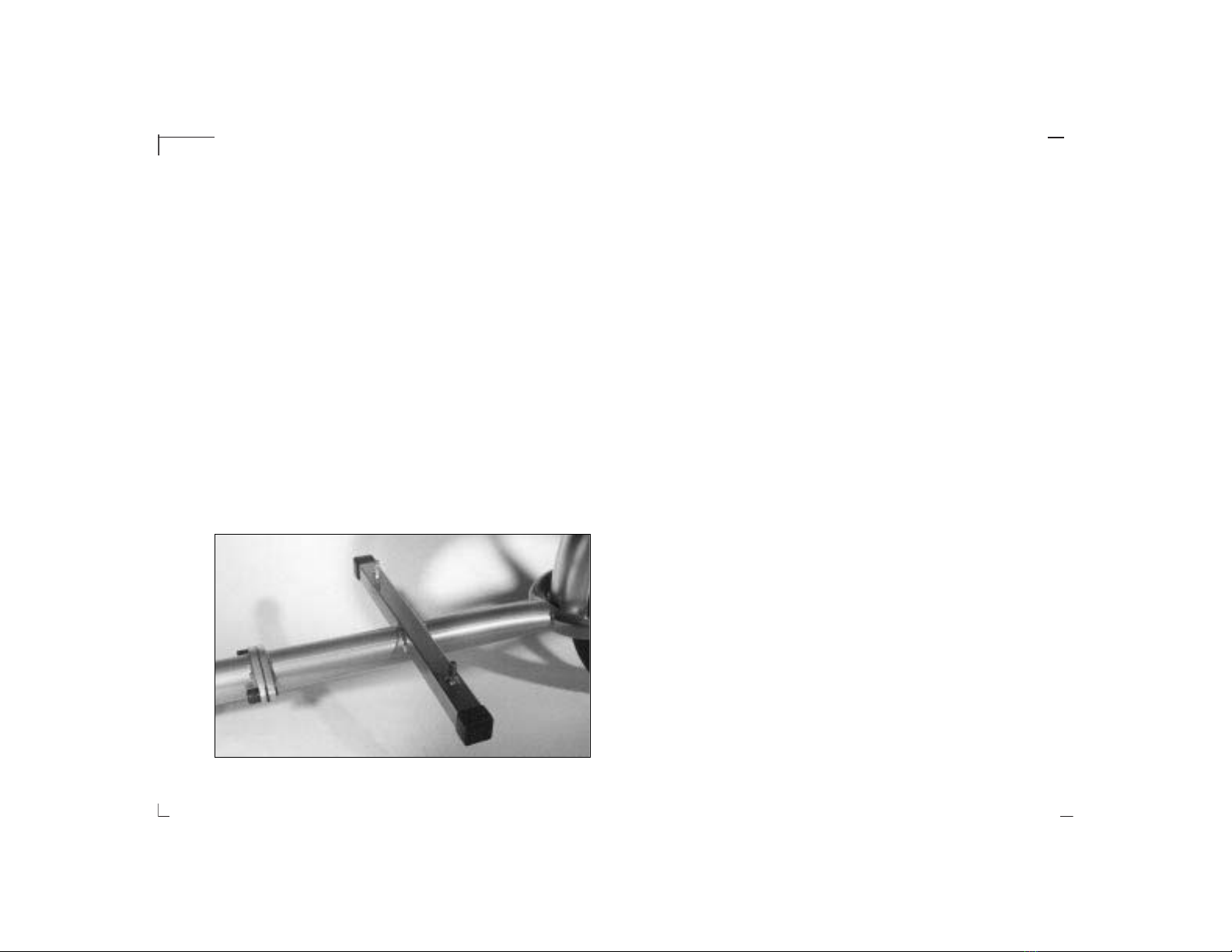
FIG. 20 YAK Safety Flag Pole installed in mounting bracket.
reflector. This reflector configuration will keep the trailer
wheel balanced and vibration free.
Safety Flag - The trailers come with a two piece safety
flag. The two pieces are attached to one another by means
of a metal ferrule. Press the two metal ends of the flag sec-
tions together making sure they insert into one another
completely. After attaching the two flag sections install into
the flag mounting bracket located on the left wheel stay as
shown in Fig. 19 (COZ) Install into the flag mounting brack-
et located on the back of the cargo stop as shown in Fig. 20
(YAK). The flag is extremely important in helping to make
you visible to others. You should always make sure the flag
is correctly installed when using your trailer.
When removing the flag it is best to first remove it from the
FIG. 19 COZ Safety Flag Pole installed in mounting bracket.

rod is fastened to the upper and lower pivot plates by two
6mm Allen bolts and lock washers. Fig. 22. As a final check
before attaching your trailer, make sure these bolts are
securely tightened.
To tighten properly, insert a 5mm Allen wrench in each
screw (top and bottom) and tighten against one another
simultaneously.
B.O.B QUICK RELEASE INSTALLATION
Fig. 23 shows the anatomy of a B.O.B quick release. Study
this diagram carefully and become familiar with the names
of the various parts. This will assist you in understanding
the following instructions. The B.O.B quick release must
first be fitted to your bicycle before the trailer can be at-
tached. The quick release installation procedure is as follows:
17
FIG. 21 Tighten COZ front fork pivot screw in the upper and lower pivot.
FIG. 23 Anatomy of a B.O.B Quick Release (QR).FIG. 22 Tighten YAK front fork pivot screws in the upper and lower pivot.
Retaining
Screw
Adjusting NutRod
Conical
Spring
Lever Bobbin
Flat
Washer
Lock
Washer

a. To determine the spacing of your frame, measure the
dimension of your dropouts using a pair of calipers as
shown in Fig. 25.
NOTE: If you do not understand the following instructions,
your dealer can modify the length of the Quick Release rod
as necessary to fit your bicycle properly. To determine the
correct quick release rod length for your bike proceed as
follows:
b. The design of the B.O.B quick release allows for an 11
mm variation between minimum and maximum rod lengths.
Many people have both road and mountain bikes. Mountain
bikes typically have wider dropout spacing than road bikes.
However, the variation between the bikes is usually less
than 11 mm and allows the rod to be used in both bikes. If
18
FIG. 25 Measurement of outside to outside dimension of rear dropouts.
FIG. 24 Bicycle quick release in open position.
1) Remove your bike’s rear wheel quick release by:
a. Moving the quick release lever from the closed to open
position parallel to the bike frame as shown in Fig. 24. The
word OPEN should be visible on the lever.
b. Next unscrew the adjusting nut, Fig. 14, by holding the
lever in place and turning the adjusting nut in the counter-
clockwise direction. Also remove the conical shaped spring.
c. Remove the skewer by pulling it through the hub in the
direction of the lever.
2) For the B.O.B quick release to safely work with your
bicycle, the overall dimension from outside to outside of
your bike frame’s rear wheel dropouts must fall within the
following range:
Minimum: 140mm Maximum: 156 mm
This manual suits for next models
1
Table of contents


