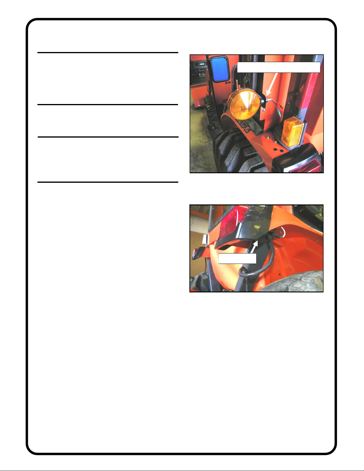
Curtis KUBOTA B3200 Operating instructions

INSTALLATION & OWNER’S MANUAL
Rev. A, p. 1 of 12
The contents of this envelope are the property of the owner.
Be sure to leave with the owner when installation is complete.
KUBOTA B3200
Hard Sided Cab p/n 1KB32AS
Soft Sided Cab p/n 1KB32SS
Installation Instructions
APPROXIMATE INSTALLATION TIME: 2 to 3 HOURS
(excluding accessories)
Hard sided cab shown with optional work lights, and optional strobe light.
Additional options available are: heater, hard rear panel, and rear window wiper.
Note: a front windshield wiper comes standard with this cab kit.
manual p/n: IM-1KB32AS

DESIGN CONCEPT
Curtis cabs feature an assembly of parts designed for your vehicle which require
adjustment and alignment of components to accommodate vehicle variations and
provide proper weather protection. For accurate installation, proper operation, and
years of satisfaction, please read and understand the installation instructions.
From all of us at Curtis, we thank you for choosing our product.
CAB INSTALLATION
BEFORE YOU START
HELPFUL HINTS:
A. Refer to parts diagram toward the back of this manual
to help identify parts during the assembly process.
B. To assist with the cab installation, leave all bolts
loose for later adjustment unless otherwise specified.
C. Read and understand all instructions before beginning.
D. Plastic washers have been supplied to provide a
weather seal under the heads of all exterior bolts.
The plastic washer should be installed under each
bolt head directly against the outside cab surface.
Care should be taken not to over tighten the fast-
eners and damage the plastic washer. Also use
steel washers as required. See diagram.
E. Apply a silicone sealant to seal any minor
gaps that may occur due to vehicle variations.
F. Use caution to avoid damaging the factory installed
threaded inserts. Begin the bolt engagement by hand
to avoid or correct potential cross threading.
TOOLS REQUIRED
driver and passenger.
Curtis accessory weights are listed in product
add additional weight to the base vehicle. All
Curtis Cabs, blades and general accessories
ADDED
WEIGHT
brochures. Deduct the accessory's total weight
from the vehicle's rated capacity and never
exceed the vehicle's rated capacity including
Exposure to Carbon Monoxide can Cause
illness, serious injury or death. Never
operate vehicle if suspicious of Carbon Monoxide. Inspect
exhaust system for leaks monthly. Leaks can result from loose
connections, corrosion, cracks or other damage to the exhaust
manifold. If leaks are found, repair or replace exhaust system.
Do not use vehicle until repair or replacement is complete.
p. 2 of 12
Fastener
Cab Surface
Steel Washer
Plastic Washer
Set of standard and metric sockets
Set of standard and metric open end wrenches
Drill
3/8" drill bit
Measuring Tape
Clamp
One Phillips Head Screwdriver
Scissors
One 3/8” Drive Ratchet
One 5/32” Allen Wrench (preferably “T” handle type)
One 3/16” Allen Wrench (preferably “T” handle type)

p. 3 of 12
1. VEHICLE PREP
1.1 Per fig. 1.1, remove the following five (5) items
from the tractor: the optional tool box and clamps from
the roll bar (if equipped), both grab handles, and both
turn signal lights from the fenders (identify the wires for
easier re-connection later). Save the turn signal lights,
washers, and nuts for re-use in step 14.
2. VIBRATION MOUNTS
2.1 Per fig. 2.1, install the rubber vibration mounts to
the outer surface of the roll bar mounts as oriented in the
photo (with the bend down). Use four 1/4-20 x 1” long
button head bolts, four steel washers, and four locknuts.
The head of the bolt is to be in the recessed pocket. The
washers go on the same side as the locknuts. Snug up the
bolts. Do not over-tighten.
3. ROLL BAR BRACKETS
3.1 Per figures 3.1 and 3.1.1, loosely install the roll bar
brackets and the roll bar mounts to the R.O.P.S. tubing as
shown (two places per upright) (approximately where
shown in relationship to the removable pin for the fold-
down R.O.P.S.. Ref.: approximately 14” up from the
fender and 36” up from the fender. When left loose, these
units will be able to slide up or down to match the exact
mounting holes in the back of the side frames. Orient the
roll bar mount so the rubber vibration mount is against
the front surface of the tubing and the bent end of the
part is forward and outboard. Use the following hardware
per setup: two 5/16-18 x 1” long carriage bolts, two steel
washers, and two locknuts. The washers and locknuts are
to be towards the rear of the tractor.
Fig. 1.1 (remove these items from tractor)
Fig. 3.1.1 (view from front left side of tractor)
NOTE: bend
is down
Fig. 2.1 (roll bar mounts)
mount to
outside
surface
Fig. 3.1 (view from front left side of tractor)
rubber vibration mount
head of
carriage bolt NOTE: bend
is forward
the bent ends
of the roll bar
mounts are to
be towards
the front of
the tractor

p. 4 of 12
4. HARD REAR PANEL
Note: this is a separately purchased option on soft sided cabs.
It’s a standard included item on hard sided cabs. If installing
on a SS cab remove snaps from rear edge of roof.
4.1 If not installing a hard rear panel, skip to step 5 below.
4.2 See fig. 4.2. With assistance, place the hard rear panel
on the tractor in front of the R.O.P.S. tubing oriented as
shown with the window towards the rear. The bulb rubber on
the bottom of the left and right sides should be pointing for-
ward. NOTE: per the inset picture in the top left hand corner
of fig. 4.2, be sure both removable pins for the fold-down
R.O.P.S. are oriented for easy outboard pin removal once the
optional hard rear panel is bolted in place.
5. COWL
5.1 Per fig. 5.1, position the cowl over the hood of the
tractor oriented so the top channel bend is towards the rear of
the tractor (fig. 6.1.1 also shows the orientation). The bulb
rubber seal around the hood area should be positioned to
point forward. As shown in fig. 6.1, the lower bent flange on
the cowl sits on top of the rubber floor mat (not under it).
6. SIDE FRAME
For ease of installation, remove the doors from side frames
by opening and lifting up off of pin hinges with the aid of an
assistant.
6.1 Per fig. 6.1, install the left side frame so the floorboard
sits on top of the rubber floor mat and on top of the bent
flange on the lower portion of the orange cowl as shown. Per
fig. 6.1.1, the mounting tab that is welded on to the side
frame fits into the bent channel on the cowl as shown. The
bulb rubber that seals against the rear fender should be point-
ing outboard to minimize covering the factory installed de-
cals.
Fig. 4.2 (view from front left side of tractor)
Fig. 5.1 (view from front left side of tractor)
Fig. 6.1 (view from rear left side of tractor)
bulb rubber
to point
forward
bent flange
on cowl
Fig. 6.1.1 (view from front left side of tractor)
mounting
tab is in here
hard rear
panel
bulb rubber
to point for-
ward

p. 5 of 12
6. SIDE FRAME (cont’d.)
6.2 Per fig. 6.2, use the following hardware installed
horizontally into the front of the side frame tubing (into
factory installed threaded inserts): three 5/16-18 x 3/4”
long button head bolts, three nylon washers, and three
steel washers. See helpful hint “D” on page 2 for proper
placement of nylon/plastic washers. Use caution to avoid
damaging the factory installed threaded inserts. Begin the
bolt engagement by hand to avoid or correct potential
cross-threading. Do not tighten bolts.
6.3 Per fig. 6.3, clamp the top corner of the cowl to the
side frame to assist in lining up the holes for the vertical
bolt. Use the following hardware in this location: one
5/16-18 x 3/4” long button head bolt, two steel washers,
and one locknut. The head of the bolt is to be up top as
shown. Tighten bolt and remove clamp.
6.4 Per fig. 6.4, attach the back side of the side frame to
the roll bar bracket assembly. Note: fig. 6.4 shows an
optional hard rear panel in place. Use the following hard-
ware in each of the four roll bar bracket assemblies: one
5/16-18 x 1” long button head bolt, one nylon washer,
and one steel washer. Thread into the factory installed
threaded inserts in the rear of the side frame tubing. Do
not tighten bolts.
6.5 For the remaining two threaded inserts per side
(one up top and one down bottom) on the back of the side
frame, leave them open if not installing a hard rear panel.
If installing a hard rear panel, use the following hardware
per side: two 5/16-18 x 3/4” long button head bolts, two
nylon washers, and two steel washers. Thread into the
factory installed threaded inserts in the rear of the side
frame tubing. Do not tighten bolts.
6.6 Repeat all of section 6 for the opposite side frame.
6.7 Per fig. 6.7, new decals can be obtained from
Kubota and repositioned on the tractor if required.
Fig. 6.3 (view from front right side of tractor)
clamp here
head of vertical bolt
Fig. 6.4 (view from rear left side of tractor)
hard rear
panel
nylon washer, steel
washer, head of bolt
Fig. 6.7 (view from center of tractor)
Fig. 6.2 (view from front left side of tractor)
install
bolts
here

p. 6 of 12
7. WINDSHIELD SUPPORT
7.1 See fig. 7.1. With assistance, install the windshield
support to the top front corner of the side frames oriented
as shown with the bent flanges on the bottom. In the low-
er holes only, use the following hardware per side frame:
one 5/16-18 x 1” long button head bolt, two steel wash-
ers, one nylon washer, and one locknut. Refer to the
helpful hints section on page two for the proper place-
ment of the nylon washer. Do not tighten bolts. Note: the
upper hole on each side will get hardware once the roof
is installed.
8. WINDSHIELD
8.1 See fig. 8.1. Have the following items ready: four
5/16-18 x 1-3/4” long flat head bolts, four steel washers,
four locknuts, and two plastic spacer blocks. With assis-
tance, install the windshield hinges to the windshield
support with the two spacer blocks between the hinge
and the windshield support. Attach windshield latches to
windshield latch receivers on the cowl by squeezing tabs
to retract spring loaded pins. See fig. 8.1.1. Lift up on
bottom of windshield and close latches. Check alignment
of windshield with side frames and tighten hinge hard-
ware. CAUTION: hinges are plastic components. Do
not overtighten hardware. Torque to 7 foot-pounds
maximum. Also tighten both lower windshield support
bolts (from step 7 above).
Fig. 7.1 (view from front left side of tractor)
install
bolt
here
leave empty for now
Fig. 8.1 (view from front right side of tractor)
3/4” thick spacer block
Fig. 8.1.1 (view from center of tractor)
latch
receiver

p. 7 of 12
middle
side bolt
Fig. 9.3 (view from front left side of tractor)
rear corner bolt
ref.: reflectors are back here
Fig. 10.2.1 (view from left side of tractor)
heads of
bolts up top
9. ROOF
9.1 Use a Phillips head screwdriver to punch a hole
through the headliner at any of the covered bolt hole lo-
cations (8 places). Punch holes from the inside out to
avoid having the headliner pull away from its glued sur-
face.
9.2 Install the roof oriented so the reflectors are to-
wards the rear of the vehicle. Use the following hardware
in the two front corners: one 5/16-18 x 1” long button
head bolt, two steel washers, one nylon washer, and one
locknut (locknuts on the inside surface). Install the bolt
through the roof, windshield support, and mounting tab.
See the helpful hints section on page two for placement
of nylon washers.
9.3 See fig. 9.3. The middle side and rear corner bolt
location on both the left and right sides uses the follow-
ing hardware per side: two 5/16-18 x 3/4” long button
head bolts, two steel washers, and two nylon washers.
These bolts are installed into factory installed threaded
inserts in the top of each side frame. NOTE: use caution
to avoid damaging the internal threads on the factory
installed threaded inserts.
9.4 The remaining two holes in the middle front use the
following hardware: two 5/16-18 x 3/4” long button head
bolts, four steel washers, two nylon washers, and two
locknuts. Locknuts to be on the inside surface.
10. TIGHTEN ALL BOLTS
10.1 Tighten all bolts at this time including the carriage
bolts on the roll bar brackets, etc.. Note: the roll bar
brackets should end up parallel and/or perpendicular to
the R.O.P.S. tubing.
10.2 Per figures 10.2 and 10.2.1, use the two holes in
the side frame floorboard as a guide to drill 3/8” diameter
holes through the floor of the tractor. WARNING:
check underneath for obstructions before drilling.
With assistance, depress the inner-most brake pedal to
gain clearance for the drill to be vertical when drilling
the front right bolt hole. Install the following hardware
per side: two 5/16-18 x 1” long button head bolts, four
steel washers, and two locknuts. Locknuts to be under-
neath the tractor. Tighten these bolts.
Fig. 10.2 (view from seat of tractor)
drill a
3/8” hole

p. 8 of 12
11. REAR CURTAIN
If installing a hard rear panel, skip this step and continue
with step 12 below.
11.1 Assemble the six (6) snaps on the rear curtain to
the six (6) snaps on the back side of the roof.
11.2 Dry fit the sides of the rear curtain to the wide in-
ner surface of the side frame rear vertical tubing as
shown in fig. 11.2. Install the supplied 1” wide hook vel-
cro to a clean, dry surface at room temperature for best
adhesion. Attach the curtain to the newly installed velcro.
12. UNDER SEAT FILLER
12.1 Per fig. 12.1, tip/raise the seat forward and position
the under seat vinyl filler as shown with the seat belt
bracket passing through the slit openings on each side.
Dry fit this and estimate where to apply the supplied 1”
wide hook velcro to the fenders, etc.. Reminder: for best
adhesion, apply self-adhesive backed velcro to clean, dry
surfaces at room temperature. The top middle section of
the under seat filler attaches to the bottom of the soft rear
curtain or to the bottom inside surface of a hard rear pan-
el as shown in fig. 12.1.1. For the hard rear panel, install
more of the supplied 1” wide velcro to suit.
Fig. 11.2 (view from center of tractor)
2” wide inner surface
of side frame rear
vertical tube
Fig. 12.1 (view from left side of tractor)
seat belt
bracket
opening
Fig. 12.1.1 (view from left side of tractor)
hard rear panel
is shown here

p. 9 of 12
13. DOORS
13.1 Apply grease to the pin hinges. With assistance, re
-install the doors onto the pin hinges. Work the doors
back and forth until the hinges are completely seated. If
necessary, specific adjustments can be made per the steps
below. Note: the top of the door should end up visually
parallel with the side of the roof. Note: the door latch is a
rotary type with two positions to close. Adjust door so
that when fully closed door latch clicks twice for total
engagement.
Per fig. 13.2, the large striker bolt and nut can be loos-
ened and reset higher or lower, in or out for better en-
gagement and door seal. Use two 19mm open end
wrenches. Note: finger guard to end up being centered
and facing inward.
Per fig. 13.3, the 1/4-20 hex head bolts on the door hing-
es can be loosened on the rear tube, or on the door itself,
or in both places, in order to rotate or move the door up
or down and forward or backward as necessary for prop-
er alignment with side frame. Note: An assistant will be
needed for this step. Keep the hinge sleeves fully seated
on the pin hinges. Tighten all hinge bolts using caution to
not over tighten. Over tightening will crush (damage) the
structural tubing. Torque to 40 inch-pounds.
Per fig. 13.4, the inside latch can be moved forward or
back for proper engagement with the striker bolt. Loosen
the two hex head bolts shown to move the latch. Re-
tighten bolts.
CAUTION: FOR SAFE OPERATION, DO NOT
DRIVE WITH DOORS OPEN. MAKE SURE
DOORS ARE CLOSED AND PROPERLY
LATCHED WHEN DRIVING.
For soft sided doors, install the supplied vinyl coated
cable door stops between the upper bracket on the doors
and the upper bracket on the side frames. Use the follow-
ing hardware: four 5/16-18 x 3/4” long hex head bolts,
eight steel washers, and four locknuts. Do not tighten
down firmly. Allow for free pivoting.
For hard sided doors, install the supplied gas shocks to
the factory installed ball studs on the side frames and
doors with the small piston end towards the door.
Fig. 13.2 (view of striker bolt assembly)
Fig. 13.3 (exterior view of right side door)
Fig. 13.4 (interior view of right side door latch)
RIGHT

p. 10 of 12
14. TURN SIGNAL LIGHTS
14.1 Per fig. 14.1, re-install the turn signal light to the
welded bracket on the back side of the side frames. Use
the supplied wires to connect to the existing wiring un-
derneath the fender (see fig. 14.1.1). Repeat for opposite
side.
15. WINDSHIELD WIPER
15.1 Install the wiper motor per the installation instruc-
tions included with the wiper kit.
16. FINISHING TOUCHES
16.1 Peel protective film from the windows.
16.2 Install the supplied nut covers on the interior lock-
nuts (qty.: 20).
17. CARE AND MAINTENANCE
17.1 Once the doors are properly adjusted, lubrication
(preferably grease) can be applied to the striker bolts and
door latch assemblies. Re-apply periodically as needed
(same goes for the door pin hinges as necessary).
17.2 Check and tighten hardware after 40 hours of op-
eration. Periodically inspect and tighten hardware for the
remainder of the unit’s life.
17.3 Wash the painted surfaces of the unit with com-
mercial automotive cleaning products.
17.4 Clean windows with glass cleaner.
17.5 Vinyl components should be washed with a mild
solution of warm soapy water.
17.6 Clear vinyl can be easily scratched. Be careful
cleaning frost or snow from rear curtain. Do not roll cur-
tain in cold weather. The curtain becomes stiff and may
crack. Keep curtain clean.
Fig. 14.1 (view from rear left side of tractor)
both washers and nut on this side
Fig. 14.1.1 (view from rear right side of tractor)
connect wires

p. 11 of 12
ADDITIONAL SERVICE PARTS
*IN HOUSE APPLICATIONS
CABS/BLADES/SPREADERS/ACCESSORIES
P/N
8SV-KB3206-03
REAR
PANEL
1
QTY.
1" FLAT BULB
*
UNDER SEAT
ORANGE
FILLER P/N
8SV-KB3210-VK1
QTY.
9SV-HWS
QTY./UNIT
8SV-SWC2R
8SV-SWC2L
9SV-HDR1
9SV-GS02
9SV-OHRL
9SV-IHRL
9SV-WL1
KB32HWK-01
1
1
1
1
1
1
1
1
1
P/N
OUTSIDE DOOR HANDLES W/ KEY (2)
DOOR HINGE KIT - LEFT AND RIGHT
DOOR GAS SPRINGS
DOOR LATCH KIT LEFT AND RIGHT
RIGHT DOOR SLIDING WINDOW
LEFT DOOR SLIDING WINDOW
WINDSHIELD LATCH KIT (2 LATCHES)
WINDSHIELD HINGE KIT (2 HINGES)
DESCRIPTION
HARDWARE KIT
HEADLINER
**TRIM-LOK BULB W/
INSIDE SURFACES)
1-1/8" HEYCO
PLUGS
*
SIDE FRAMES
5/16-18
INSERTS
LEFT
RIGHT
9/SIDE
(INSIDE)
LABEL
HEATER
*LATCH PIN
*
RIGHT
RAVEN T1 *
HINGE PINS
PLATES
& HINGE
LEFT
*LH,RH
(1/4" GRIP &
2 WIPERS)
*FIVE
CLIPS
WINDOW
SIDE WINDOW
W/ 7/16" SIDE BULB
8SV-32AS9R-B41
*
8SV-32AS9L-B4
P/N
1
QTY.
RIGHT
LEFT
HARD DOORS
ORANGE
P/NQTY.
8SV-KB32AS7R-O3
8SV-KB32AS7L-O3
1
1
DECALS (INSIDE)
(SERIAL #, R.O.P.S.,
& OPTIONS)
7/16" HEYCO
*PLUGS
SUPPORT
RAVEN T1 *
QTY.
1
WINDSHIELD
SEAL (INSIDE)
1" FLAT BULB
*
SEAL (INSIDE)
(L & R SIDES)
1/2" WEATHER
*
(L & R SIDES)
* ARCH PSA
2 PCS. (ALL 3
QTY.
MOUNTS
WINDSHIELD LATCH
*
1/2" WEATHER
*
8SV-KB2303-B4
P/N
ORANGE *
COWL
1
3 SIDES
LATCHES
ROLL BAR
RAVEN T1
BRACKET
8SV-KB3204-03
P/N
4
QTY.
1/4" GRIP &
2 WIPERS
9SV-PR09-10
ARCH PSA (10')
7/16" SIDE BULB
2 WIPERS (15')
W/ 1/4" GRIP &
9SV-PR29-15
9SV-PR05-10
1" FLAT BULB
9SV-PR38-15
2 WIPERS (15')
3/4" SIDE BULB
W/ 1/4" GRIP &
9SV-PR01-10
TRIM LOK (10')
8SV-KB2312-B4
P/N 9SV-PR20-10
1/2" WEATHER
SEAL (10')
KUBOTA B3200 HARD SIDED CAB PARTS LIST
QTY.
REFLECTORS
*LOGO
WHITE *
ROOF
1
QTY.
8SV-KB2301A-W1
P/N ROLL BAR
HINGES
*
3/4" SIDE
*
RAVEN T1
BRACKET MNT
SEAM BULB
QTY.
INDUSTRIES, LLC.
WINDSHIELD
8SV-CI02
P/N
1
RUBBER TYPES:
8SV-KB3205-B4
P/N
4
9SV-PR17-20
3/4" SIDE BULB (20')
*
HANDLE
OUTSIDE
*
1" HEYCO
LATCH
DOOR
PLUG
*GRAB
HANDLE LEFT
RIGHT
*
*HINGE
SLEEVES
3/4" SIDE BULB
*
1" FLAT BULB
*
1/2" WEATHER
(L & R SIDES)
SEAL (INSIDE)
*
INSERTS
POLY
*
KB32HWK-02
1REAR PANEL HARDWARE KIT
BALL STUD
*
ORANGE
BALL STUD
*
GRAB HANDLE KIT (2 HANDLES)
9SV-GH
1

p. 12 of 12
W/ 1/4" GRIP
HANDLE
HARDWARE KIT (CAB)
1KB32HWK-01
ADDITIONAL SERVICE PARTS
CABS/BLADES/SPREADERS/ACCESSORIES
QTY./UNIT
*IN HOUSE APPLICATIONS
P/N
CURTAIN
ORANGE
REAR
KB23-08
P/N
1
QTY.
1" FLAT BULB
DESCRIPTION
8SV-KB3210-VK
ORANGE
UNDER SEAT
FILLER QTY.
1
P/N
9SV-HWS
9SV-WL1
9SV-IHRL
9DL01B
9SV-GH
9SV-DS02
9SV-HDR1
1
1
1
1
1
1
1
WINDSHIELD HINGE KIT (2 HINGES)
WINDSHIELD LATCH KIT (2 LATCHES)
DOOR LATCH KIT - LEFT AND RIGHT
ROTARY DOOR LATCH - RH
CABLE DOOR STOP KIT
DOOR HINGE KIT - LEFT AND RIGHT
GRAB HANDLE KIT (2 HANDLES)
BULB W/
TRIM-LOK
*
*HEADLINER
P/N
8SV-KB2312-B4
5/8" SIDE BULB
PLUGS
*
SIDE FRAMES
W/ 7/16" SIDE BULB
(1/4" GRIP &
*
SIDE WINDOW
RIGHT
LATCH PIN
*
HEATER
LABEL
(INSIDE)
*
LEFT
9/SIDE
RIGHT
LEFT
INSERTS
5/16-18
*
8SV-32SS9R-041
*
P/NQTY.
1 8SV-32SS9L-B4
RIGHT
HANDLE
*
PLUG
1" HEYCO
LATCH
DOOR
& HINGE
PLATES *
HINGE PINS
LH,RH
GRAB
*
*OUTSIDE
*
LEFT HINGE
*SLEEVES
SOFT DOORS
ORANGE VINYL)
BLACK (WITH
FIVE
*WINDOW
CLIPS
2 WIPERS)
QTY.
LEFT
RIGHT
1
1
P/N
8SV-KB32SS7L-O3
8SV-KB32SS7R-O3
1/2" WEATHER
(L & R SIDES)
SEAL (INSIDE)
& OPTIONS) SEAL (INSIDE)
7/16" HEYCO
*PLUGS *
(L & R SIDES)
SUPPORT
WINDSHIELD
P/N
8SV-KB2303-B4
(SERIAL #, R.O.P.S.,
DECALS (INSIDE)
*
1
QTY.
1/2" WEATHER
*
3 SIDES
1-1/8" HEYCO
*
1" FLAT BULB
* ARCH PSA
INSIDE SURFACES)
2 PCS. (ALL 3
2 WIPERS
1/4" GRIP &
WINDSHIELD LATCH
*
ORANGE
COWL
MOUNTS
*
QTY.
1
P/N
8SV-KB3204-03
LATCHES
ROLL BAR
BRACKET
4
QTY.
KUBOTA B3200 SOFT SIDED CAB PARTS LIST
*LOGO
WHITE REFLECTORS
*
SNAPS (6)
*(INSIDE)
QTY.
ROOF P/N
8SV-KB2301-W11 ROLL BAR
SEAM BULB
3/4" SIDE
*HINGES
*
BRACKET MNT QTY.
4
INDUSTRIES, LLC.
8SV-CI02
WINDSHIELD QTY.
1
P/N
5/8" SIDE BULB
W/ 1/4" GRIP (15')
P/N
8SV-KB3205B4
RUBBER TYPES:
*
RAVEN T1
RAVEN T1
RAVEN T1
RAVEN T1
9SV-PR09-10
ARCH PSA (10')
9SV-PR29-15
2 WIPERS (15')
W/ 1/4" GRIP &
7/16" SIDE BULB
2 WIPERS (15')
1" FLAT BULB
9SV-PR05-10
9SV-PR38-15
W/ 1/4" GRIP &
3/4" SIDE BULB
9SV-PR01-10
9SV-PR20-10
TRIM LOK (10')
1/2" WEATHER
SEAL (10')
This manual suits for next models
2
Table of contents
Other Curtis Utility Vehicle manuals
Popular Utility Vehicle manuals by other brands

Craftsman
Craftsman 123.24201 user manual

BV Powersports
BV Powersports TrailMaster Cheetah6 Quick assembly guide

Yepp
Yepp solo User instructions

SUN COUNTRY
SUN COUNTRY Gooseneck SERIES owner's manual

Prime Karts
Prime Karts Racer owner's manual

Raven
Raven SmarTrax John Deere 8X60 Series installation manual