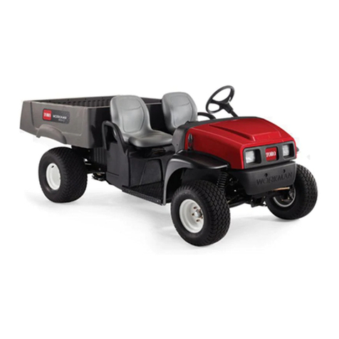
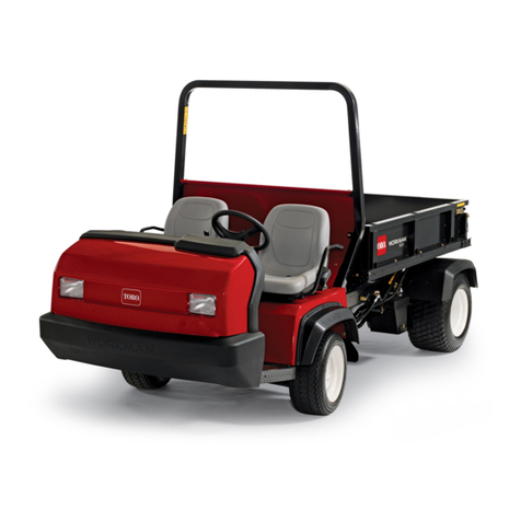
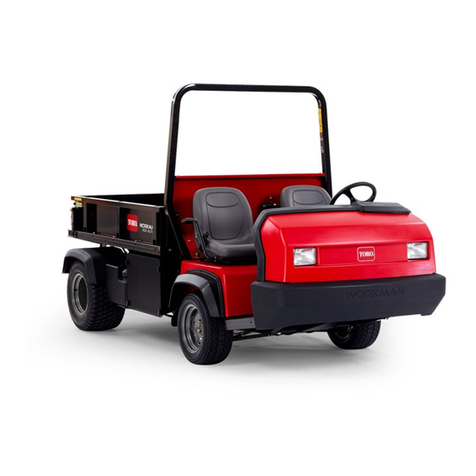
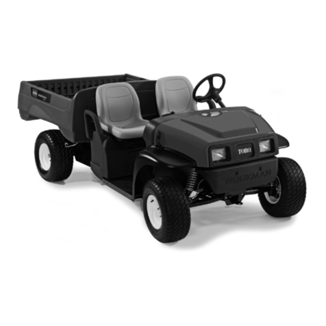
Toro 07211TC User manual

Form No. 3326-210
Operator’s Manual
®
Workman®3200 & 4200
Liquid-Cooled Gas Utility Vehicle
Model No. 07211TC—Serial No. 220000001 and Up
Model No. 07218—Serial No. 220000001 and Up
English (GI)

Foreword
The TORO Workman®was developed to provide an
efficient, versatile, trouble free and economical work
vehicle. The latest concepts of engineering, design and
safety have been incorporated into this machine, along
with the highest quality parts and workmanship.
Excellent service will be derived if proper operation
and maintenance practices are followed.
You know, since you have purchased the industry
leader in maintenance excellence, that future
performance and dependability are of prime
importance. TORO also is concerned about future use
of the machine and of safety to the user. Therefore,
this manual must be read by you and those involved
with the Workman®to make sure that safety, proper set
up, operation and maintenance procedures are
followed at all times. The major sections of the manual
are:
1. Safety Instructions
2. Set-Up Instructions
5. Maintenance
3. Before Operating
4. Operating Instructions
Safety, mechanical and some general information in
this manual are emphasized. DANGER, WARNING
and CAUTION identify safety messages. Whenever
the triangle safety symbol appears, it is followed by a
safety message that must be read and understood. For
more details concerning safety, read the safety
instructions on pages 5–7. identifies
special mechanical information and NOTE identifies
general information worthy of special attention.
The TORO Workman®meets the requirements of
ANSI B56.8a–1994.
Supervisors, operators and service persons should be
familiar with the following standards and publications:
(The material may be obtained from the address
shown).
•Flammable and Combustible Liquids Code:
ANSI/NFPA 30
•National Fire Protection Association:
ANSI/NFPA # 505; Powered Industrial Trucks
ADDRESS: National Fire Prevention
Association, Barrymarch Park, Quincy,
Massachusetts 02269 U.S.A.
•ANSI/ASME B56.8 Personal Burden Carriers
ADDRESS: American National Standards
Institute, Inc. 1430 Broadway, New York, New
York 10018 U.S.A.
•ANSI/UL 558; Internal Combustion Engine,
Powered Industrial Trucks
ADDRESS: American National Standards
Institute, Inc., 1430 Broadway, New York, New
York 10018 U.S.A.
OR
Underwriters Laboratories, 333 Pfingsten Road,
Northbrook, Illinois 60062 U.S.A.
Optional Spark Arrester
In some places a spark arrester muffler must be used
because of local, state or federal regulations. The spark
arrester, available from your local Toro Distributor is
approved by the United States Department of
Agriculture and the United States Forest Service.
When the machine is used or operated on any
California forest, brush or grass covered land, a
properly operating spark arrester must be attached to
the muffler. The operator is violating state law, Section
442 Public Resources Code if a spark arrester is not
used.
If help concerning set up, operation, maintenance or
safety is ever needed, contact your local Authorized
TORO Distributor. In addition to genuine TORO
replacement parts, the distributor also has optional
equipment for the complete line of TORO turf care
equipment. Keep your TORO all-TORO. Buy genuine
TORO parts and accessories.
Important
2
The Workman®is an off-highway vehicle only, and
is not designed, equipped, or manufactured for use
on public streets, roads or highways.
WARNING
Diesel engine exhaust and some of its constituents
are known to the State of California to cause cancer,
birth defects, or other reproductive harm.
WARNING

Table of Contents
Page
Foreword 2
Table of Contents 3
Safety Instructions 4
Sound Pressure Level 7
Vibration Level 7
Safety and Instruction Decals 8
Specifications 10
Set-Up Instructions 12
Loose Parts Chart 12
Install Rear Fenders 13
Install Wheels 13
Install Steering Wheel 13
Install Front Fenders 14
Install the Roll-Over Protection System 14
Activate and Charge the Battery 14
Full Bed Removal (Model 07212 only) 15
Re-install the Full Bed (Model 07212 only) 16
Before Operating 18
Check Engine Oil 18
Fill the Fuel Tank 19
Check the Cooling System 20
Check Hydraulic Fluid 20
Check Front Differential Oil 21
Check Torque of Wheel Nuts 21
Check Tire Pressure 21
Check Brake Fluid 22
Controls 23
Operating Instructions 26
Pre-Starting Checks 26
Starting the Engine 26
Stopping the Vehicle 27
Stopping the Engine 27
New Vehicle Break-In 27
Checking the Interlock System 27
Operating Characteristics 27
Passengers 28
Speed 28
Turning 28
Braking 28
Hills 30
Loading and Dumping 31
Using the Differential Lock 31
Four-Wheel Drive 32
Page
Transporting the Vehicle 32
Towing the Vehicle 32
Trailer Towing 33
Remote Hydraulic Control (Optional) 33
Quick Coupler Operation 35
Remote Hydraulic Control Trouble Shooting: 35
Maintenance 36
Quick Reference Chart 37
Fluid Specifications/Change Intervals 37
Lubrication 38
Using Bed Safety Support 39
Jacking the Vehicle 40
General Air Cleaner Maintenance Practices 41
Servicing the Air Cleaner 41
Changing Engine Oil and Filter 42
Fuel System 42
Removing Debris from Engine Cooling System 42
Changing Engine Coolant 43
Adjusting Belts 44
Adjusting Accelerator Pedal 44
Changing Transaxle/Hydraulic Fluid 45
Replacing Hydraulic Filter 45
Change Front Differential Oil 45
Cleaning Hydraulic Strainer 46
Replacing Spark Plugs 46
Adjusting the Brake Pedal 47
Adjusting the Clutch Pedal 47
Adjusting Parking Brake 48
Adjusting Shift Cables 48
Adjusting the High-Low Cable 49
Adjusting Differential Lock Cable 49
Inspect Brakes 49
Inspect Tires 49
Front Wheel Toe-In 49
Inspect Constant Velocity Boot 50
Emergency Box Raising 50
Fuses 50
Jump Starting Procedure 50
Battery Storage 51
Battery Care 51
Maintenance Schedule 52
Hydraulic Schematic (Base Vehicle) 53
Hydraulic Schematic (Vehicle w/Remote
Hydraulic Kit) (MODEL 07211 TC Only) 54
Electrical Schematic (Base Vehicle) 55
Electrical Schematic (Vehicle w/Remote
Hydraulic Kit) (MODEL 07211 TC Only) 56
Identification And Ordering 57
3

Safety Instructions
The Workman®was designed and tested to offer
safe service when operated and maintained
properly. Although hazard control and accident
prevention partially are dependent upon the design
and configuration of the machine, these factors are
also dependent upon the awareness, concern, and
proper training of the personnel involved in the
operation, maintenance and storage of the machine.
Improper use or maintenance of the machine can
result in injury or death.
This is a specialized utility vehicle designed for off-
road use only. Its ride and handling will have a
different feel than what drivers experience with
passenger cars or trucks. So take time to become
familiar with your Workman®.
Not all of the attachments that adapt to the
Workman®are covered in this manual. See the
specific Operator’s Manual provided with
attachment for additional safety instructions.
READ THESE MANUALS.
TO REDUCE THE POTENTIAL FOR INJURY
OR DEATH, COMPLY WITH THE
FOLLOWING SAFETY INSTRUCTIONS.
Supervisor’s Responsibilities
1. Make sure operators are thoroughly trained and
familiar with the operator’s manual and all labels
on the vehicle.
2. Be sure to establish your own special procedures
and work rules for unusual operating conditions
(e.g., slopes too steep for vehicle operation). Use
the 3rd high lockout switch if high speed could
result in a safety or vehicle abuse situation.
Before Operating
3. Operate the machine only after reading and
understanding the contents of this manual. A
replacement manual is available by sending
complete model and serial number to:
The Toro Company 8111 Lyndale Avenue South,
Bloomington, Minnesota 55420-1196.
4. Never allow children to operate the vehicle. Never
allow adults to operate it without proper
instructions. Only trained and authorized persons
should operate this vehicle. Make sure all
operators are physically and mentally capable of
operating the vehicle. Anyone who operates the
vehicle should have a motor vehicle license.
5. This vehicle is designed to carry only you, the
operator, and one passenger in the seat provided
by the manufacturer. Never carry any other
passengers on the vehicle.
6. Never operate the vehicle when under the
influence of drugs or alcohol.
7. Become familiar with the controls and know how
to stop the engine quickly.
8. Keep all shields, safety devices and decals in
place. If a shield, safety device or decal is
malfunctioning, illegible, or damaged, repair or
replace it before operating the machine.
9. Always wear substantial shoes. Do not operate
machine while wearing sandals, tennis shoes or
sneakers. Do not wear loose fitting clothing or
jewelry which could get caught in moving parts
and cause personal injury.
10. Wearing safety glasses, safety shoes, long pants
and a helmet is advisable and required by some
local safety and insurance regulations.
11. Keep everyone, especially children and pets,
away from the areas of operation.
12. Before operating the vehicle, always check all
parts of the vehicle and any attachments. If
something is wrong, stop using vehicle. Make
sure problem is corrected before vehicle or
attachment is operated again.
13. Since gasoline is highly flammable, handle it
carefully.
A. Use an approved fuel container.
B. Do not remove cap from fuel tank when
engine is hot or running.
4

C. Do not smoke while handling fuel.
D. Fill fuel tank outdoors and to about one inch
below top of tank (bottom of filler neck). Do
not overfill.
E. Wipe up any spilled fuel.
14. Check the safety interlock system daily for proper
operation; refer to page 27. If a switch should
malfunction, replace the switch before operating
machine. After every two years, replace the
interlock switches in the safety system, whether
they are working properly or not.
While Operating
15. Operator and passenger should remain seated
whenever the vehicle is in motion. Operator
should keep both hands on steering wheel,
whenever possible and passenger should use hand
holds provided. Keep arms and legs within the
vehicle body at all times. Never carry passengers
in box or on attachments. Remember your
passenger may not be expecting you to brake or
turn and may not be ready.
16. Never overload your vehicle. Name plate (located
under dash on passenger side) shows load limits
for vehicle. Never overfill attachments or exceed
the vehicle maximum gross vehicle weight.
17. When starting the engine:
A. Sit on operator’s seat and engage parking
brake.
B. Disengage any attachments and return hand
throttle lever to OFF position (if so
equipped).
C. Move shift lever to NEUTRAL and depress
clutch pedal.
D. Keep foot off accelerator pedal.
E.. Turn ignition key to START.
18. Using the machine demands attention. Failure to
operate vehicle safely may result in a accident, tip
over of vehicle and serious injury or death. Drive
carefully. To prevent tipping or loss of control:
A. Use extreme caution, reduce speed and
maintain a safe distance around sand traps,
ditches, creeks, ramps, any unfamiliar areas
or other hazards.
B. Watch for holes or other hidden hazards.
C. Use caution when operating vehicle on a
steep slope. Normally travel straight up and
down slopes. Reduce speed when making
sharp turns or when turning on hillsides.
Avoid turning on hillsides whenever
possible.
D. Use extra caution when operating vehicle on
wet surfaces, at higher speeds or with a full
load. Stopping time will increase with a full
load. Shift into a lower gear before starting
up or down a hill.
E. When loading bed, distribute load evenly.
Use extra caution if the load exceeds the
dimensions of the vehicle/bed. Operate
vehicle with extra caution when handling
off-center loads that cannot be centered.
Keep loads balanced and secure to prevent
them from shifting.
F. Avoid sudden stops and starts. Do not go
from reverse to forward or forward to reverse
without first coming to a complete stop.
G. Do not attempt sharp turns or abrupt
maneuvers or other unsafe driving actions
that may cause a loss of vehicle control.
H. When dumping, do not let anyone stand
behind vehicle and do not dump load on any
one’s feet. Release tailgate latches from side
of box, not from behind.
I. Before backing up, look to the rear and
assure no one is behind. Back up slowly.
J. Watch out for traffic when near or crossing
roads. Always yield the right of way to
pedestrians and other vehicles. This vehicle
is not designed for use on streets or
highways. Always signal your turns or stop
early enough so other persons know what
you plan to do. Obey all traffic rules and
regulations.
K. Never operate vehicle in or near an area
where there is dust or fumes in the air which
are explosive. The electrical and exhaust
systems of the vehicle can produce sparks
capable of igniting explosive materials.
L. Always watch out for and avoid low over
hangs such as tree limbs, door jambs, over
head walkways, etc. Make sure there is
enough room over head to easily clear the
5
vehicle and your head.
M. If ever unsure about safe operation, STOP
WORK and ask your supervisor.
19. Do not touch engine, transaxle, radiator, muffler
or muffler shield while engine is running or soon
after it has stopped because these areas may be
hot enough to cause burns.
20. If the machine ever vibrates abnormally, stop
immediately, turn engine off, wait for all motion
to stop and inspect for damage. Repair all damage
before commencing operation.
21. Before getting off the seat:
A. Stop movement of the machine.
B. Lower the bed.
C. Shut engine off and wait for all movement to
stop.
D. Set parking brake.
E. Remove key from ignition.
F. Block wheels if machine is on an incline.
Maintenance
22. Before servicing or making adjustments to the
machine, stop engine, set parking brake and
remove key from ignition to prevent accidental
starting of the engine.
23. Never work under a raised bed without placing
bed safety support on fully extended cylinder rod.
24. Make sure all hydraulic line connectors are tight,
and all hydraulic hoses and lines are in good
condition before applying pressure to the system.
25. Keep body and hands away from pin hole leaks or
nozzles that eject hydraulic fluid under high
pressure. Use paper or cardboard, not hands, to
search for leaks. Hydraulic fluid escaping under
pressure can have sufficient force to penetrate
skin and do serious damage. If fluid is injected
into the skin it must be surgically removed within
a few hours by a doctor familiar with this form of
injury or gangrene may result.
26. Before disconnecting or performing any work on
the hydraulic system, all pressure in system must
be relieved by stopping engine, cycling dump
valve from raise to lower and/or lowering box and
attachments. Place the remote hydraulics lever in
the float position. If box must be in raised
position, secure with safety support.
27. To make sure entire machine is in good condition,
keep all nuts, bolts and screws properly tightened.
28. To reduce potential fire hazard, keep the engine
area free of excessive grease, grass, leaves and
accumulation of dirt.
29. If the engine must be running to perform a
maintenance adjustment, keep hands, feet,
clothing, and any parts of the body away from the
engine and any moving parts. Keep everyone
away.
30. Do not overspeed engine by changing governor
settings. Maximum engine speed is 3650 rpm. To
assure safety and accuracy, have an Authorized
TORO Distributor check maximum engine speed
with a tachometer.
31. If major repairs are ever needed or assistance is
required, contact an Authorized TORO
Distributor.
32. To be sure of optimum performance and safety,
always purchase genuine TORO replacement
parts and accessories. Replacement parts and
accessories made by other manufacturers could be
dangerous. Altering this vehicle in any manner
may affect the vehicle’s operation, performance,
durability or its use may result in injury or death.
Such use could void the product warranty of The
TORO Company.
33. This vehicle should not be modified without the
TORO Company’s authorization. Direct any
inquiries to:
The TORO Company Commercial Division
Vehicle Engineering Dept., 300 West 82nd St.
Bloomington, Minnesota 55420-1196 USA
6

Sound Pressure Level
This unit has an equivalent continuous A-weighted
sound pressure at the operator ear of 82 dB(A), based
on measurements of identical machines per Directive
98/37/EC and amendments.
Vibration Level
Hand Arm
This unit does not exceed a vibration level of 2.5 m/s2,
at the hands based on measurements of identical
machines per ISO 5349 procedures.
Whole Body
This unit does not exceed a vibration level of 0.5 m/s2
at the posterior based on measurements of identical
machines per ISO 2631 procedures.
7

8
SAFETY ALERT SYMBOL GENERAL HAZARD SAFETY
ALERT
CRUSHING OF WHOLE BODY,
APPLIED FROM ABOVE
CRUSHING OF FINGERS OR HAND,
FORCE APPLIED FROM SIDE
CUTTING OF FINGERS OR HAND CUTTING OF FOOT
WHOLE BODY ENTANGLEMENT,
IMPLEMENT INPUT DRIVE LINE
THROWN OR FLYING OBJECTS,
WHOLE BODY EXPOSURE
READ OPERATOR’S MANUAL LOCK UNLOCK MANUAL
CAUSTIC LIQUIDS, CHEMICAL
BURNS TO FINGERS OR HAND
KEEP CHILDREN A SAFE
DISTANCE FROM BATTERY
EXPLOSION FIRE OR OPEN FLAME FIRE, OPEN LIGHT &
SMOKING PROHIBITED
EYE PROTECTION MUST BE
WORN
CAUTION, TOXIC RISK FIRST AID FLUSH WITH WATER
BATTERY CHARGING
CONDITION
DO NOT DISPOSE IN THE
GARBAGE
STAY A SAFE DISTANCE FROM MACHINE
CRUSHING OF TOES OR FOOT,
FORCE APPLIED FROM ABOVE
FUEL TANK FILL LINE
25mm
ON/START OFF/STOP HEADLIGHTS
STAY A SAFE DISTANCE FROM DRAINING
TANK
STAY A SAFE DISTANCE FROM MACHINE STAY A SAFE DISTANCE FROM
HYDRAULIC OIL VALVE
SECURE LIFTING CYLINDER WITH
LOCKING DEVICE BEFORE GETTING
IN HAZARDOUS AREA
DO NOT OPEN OR REMOVE SAFETY
SHIELDS WHILE ENGINE IS RUNNING
HAND & ARM ENTANGLEMENT,
BELT DRIVE
CRUSHING OF TORSO,
FORCE APPLIED FROM
THE SIDE
CRUSHING OF FINGERS OR
HAND, FORCE APPLIED FROM
ABOVE
HIGH PRESSURE SPRAY,
EROSION OF FLESH
ENGINE START ENGINE STOP ENGINE LUBRI-
CATING OIL
GLOW PLUG ENGINE INTAKE,
COMBUSTION AIR
ATTACHMENT RAISE
ATTACHMENT LOWER
ATTACHMENT FLOAT LIMITED RECTI-
LINEAR MOTION
BRAKE SYSTEMENGAGE DISENGAGE FAST SLOW CONTINUOUS VARIABLE, LINEAR PARKING BRAKE DIFFERENTIAL LOCK CLUTCH LIFT POINT
HOPPER CLOSED HOPPER OPEN CLOCKWISE ROTATION COUNTER CLOCKWISE
ROTATION PROHIBITED ACTION OR
HAZARDOUS LOCATION VEHICLE BED LOWER VEHICLE BED RAISE
133 bar
PTO HYDRAULIC PRESSURE HYDRAULIC OIL PRESSURE
INTAKE AIR
3H
TRANSMISSION, 3RD
HIGH GEAR
HORN
L
TRANSMISSION, LOWTRANSMISSION OIL
< 250 kg
WEIGHT
H
TRANSMISSION, HIGH HOUR METER, ELAPSED
OPERATING HOURS
DO NOT WELD DO NOT DRILL
Safety and Instruction Decals

9
THROWN OR FLYING OBJECTS,
FACE EXPOSURE
SEVERING OF FINGERS OR
HAND, ENGINE FAN
RIDING ON THIS MACHINE IS
ALLOWED ONLY ON A PASS-
ENGER SEAT & ONLY IF THE
DRIVER'S VIEW IS NOT HINDERED
SHUT OFF ENGINE & REMOVE
KEY BEFORE PERFORMING
MAINTENANCE OR REPAIR WORK
MACHINE TIPPING USE CAUTION ON STEEP HILLS MACHINE TIPPING MACHINE TIPPING
DO NOT JUMP FROM TIPPING
MACHINE
HOLD TIGHTL & BRACE FEET LEAN AWAY FROM TIP HOLD HIP RESTRAINT & HAND
HOLD, BRACE FEET
STAY CLEAR OF ARTICULATION
AREA WHILE ENGINE IS RUNNING
RUNOVER/BACKOVER, VEHICLE REAR POWER TAKE OFF
(9)
GREASE LUBRICATION POINT GREASE LUBRICATION POINT
2. 4.
3.
1.
< 680 kg < 90 kg
< 1179 kg
635 kg
< 1814 kg
635 kg
MACHINE DIRECTION OF MOVEMENT BEFORE LEAVING OPERATOR POSITION, TURN OFF IGNITION, LOCK PARKING BRAKE,
DISENGAGE PTO, REMOVE KEY FROM IGNITION.
BEFORE LEAVING OPERATOR POSITION,
TURN OFF IGNITION AND REMOVE KEY.
LOAD RATING, HOPPER LOAD RATING, TRAILER AND HITCH
LOAD RATING
< 1179 kg
726 kg
< 1905 kg
LOAD RATING
< 318 kg
LOAD RATING, HOPPER

Specifications
Type: 4-wheel step through, out front operator style,
two-person vehicle. Certified to meet ANSI
Specifications B56.8a-1994.
Engine: Daihatsu 23.1Kw (31 hp) three-cylinder,
liquid-cooled, counterbalanced, gasoline engine;
regulated to 3650 rpm by a mechanical governor. 58.1
cu. in. (952 cc) displacement. Forced lubrication by
gear pump. 40 amp alternator with I/C regulator. Spin-
on oil filter.
Air Cleaner: Heavy-duty, 2-stage, remote mounted air
cleaner.
Battery: 12 volt with 650 cold cranking amps @ –17.8
degrees C.
Cooling System: Mid mounted radiator with
removable screen and lower clean out access. Cooling
system capacity is approximately 3.8 l (4 qts.) of 50/50
mixture of ethylene glycol anti-freeze.
Fuel System: Gasoline tank capacity is 26.5 l (7
gallons). 12-volt, electric fuel pump.
Transmission: Rear transaxle configuration, twin axle
drive. 3-speed synchromesh, H-shift pattern with high-
low range providing 6 forward and 2 reverse speeds.
Manual engage differential lock. 4-wheel drive output
shaft (4-wd only).
Clutch: 6.7” clutch and pressure plate.
Front Differential: (4-wd only) 5.0 to 1 ratio.
Center Differential: (4-wd only) Bi-directional
overrunning clutch.
Frame: Welded, high strength steel channels and
tubes.
Front Suspension: Independent “A” frame control
arm, dual progressive rate coil springs and dual shock
absorbers with anti-sway bar.
Rear Suspension: DeDion axle (weight carrying axle
is independent of transaxle), leaf spring and dual
shock absorbers.
Steering System: Power assist, 3-position tilt steering
wheel, 3-3⁄4turns lock-to-lock. 17.5 to 1 ratio, 35cm
(14”) diameter steering wheel.
Tires: Front tires: 20” x 10” 10, 4-ply rating, rib tread.
Rear tires: 23” x 13” 12, 6-ply rating, turf tread.
Brakes: 4-wheel hydraulic, dual safety circuit self-
adjusting drum: 7” diameter front and 8” diameter rear
(2-wd) 8” diameter front and rear (4-wd). Hand-
actuated parking brake actuates rear brake shoes.
Roll-over protection system: 2-post roll-over
protection structure with shoulder restraint.
Hydraulics: 4 gpm pressure-balanced gear pump
provides hydraulic flow for power steering, lift and
optional remote hydraulics. Lift control valve and dual
cylinders for lifting dump box. Transaxle is used for
reservoir for hydraulic system. 7.6 l (8 quart) total
capacity. Spin-on, 10-micron hydraulic oil filter. 100-
mesh strainer in transaxle.
Seat: Bucket seats with shoulder and hip restraints.
Controls: Foot-operated accelerator, clutch and brake
pedals. Hand-operated shifter, differential lock,
parking brake, high-low range shifter, hydraulic lift
and tilt steering levers. Ignition switch, light switch,
glow plug switch, horn button and 3rd high-lockout
switch.
Gauges: Hour meter, fuel gauge, coolant temperature
gauge. Warning light cluster includes engine low oil
pressure, and charge indicator. Tachometer optional.
Lights: Twin halogen headlights and single taillight.
Rear stop light.
Tow Hitch: Hitch has hole for ball or pin.
Interlocks: Clutch pedal must be depressed to start
engine.
10

Ground Speed:
Forward Speeds w/23” Rear Tires
High range: 12/18.5/31.9 kmh .(6/11.5/19.8 mph)
Low range: 4.7/7.2/12.4 kmh (2.9/4.5/7.7 mph)
Reverse Speeds w/24”Tires
High range: 11.6 kmh (7.2 mph)
Low range: 4.5 kmh (2.8 mph)
General Specifications (approx.):
Base Weight: Dry w/o flatbed 522.5 kg (1400lbs)
(2wd); 597kg (1600 lbs.)(4-wd)
Rated Capacity: *970.42kg ( 2,600 lbs.)
* includes 75 kg. operator and 75 kg. passenger and
loaded attachment.
Maximum. Gross Vehicle Weight: 1493kg (4,000
lbs). (2wd); 1568 kg (4,200 lbs.) (4-wd)
Tow Capacity: Tongue weight 75 kg (200 lbs.)
Maximum trailer weight 560 kg (1,500 lbs.)
Overall Width: 160cm (63”)
Overall Length: 316 cm (124.5”) w/o bed; 322cm
(127”) w/full bed 337.8cm (133”) with 2⁄3bed in rear
mounting location
Height: 190c5cm (75”) to top of roll-over protection
system
Ground Clearance: 17.8cm (7”) w/no load
Wheel Base: 177.8cm (70”)
Wheel Tread: (center line to center line)
116.8 cm (46”); Front 121cm (47.7”)
Rear Specifications and design subject to change
without notice.
11

Set-Up Instructions
Loose Parts Chart
Note: Use this chart as a checklist to assure all parts
necessary for assembly have been received. Without
these parts, total set up cannot be completed. Some
parts may have already been assembled at factory.
12
DESCRIPTION QTY. USE
Fenders-Rear 2
Capscrew 5⁄16-18 x 1” lg. 4
Flatwasher .344” I. D. 4
Locknut 5⁄16-18 4
Capscrew 1⁄4-20 x 1” lg. 12 Mount rear fenders
Flatwasher .281” I. D. 12
Locknut 1⁄4-20 12
Tr usshead Screw 6
Locknut 3⁄8-16 6
Wheel Nut 10
Wheel—Front 2
Wheel Nut 10 Mount wheels.
Wheel—Rear 2
Steering wheel 1
Foam Seal 1
Washer 1 Install steering wheel
Nut 1
Cap 1
Fenders-Front 2
Phillips Screw 10-24 14 Install front fenders
Washer 14
Locknut 10-24 14
Roll-Over Protection System 1
Capscrew 1⁄2-13 x 3” lg. 4 Mount Roll-Over Protection System
Locknuts 1⁄2-13 4
Operator’s Manual (Vehicle) 2Read before operating machine.
Parts Catalog 1
Registration Card 1Fill out and return to Toro

Install Rear Fenders (Fig. 1–2)
1. Loosen the locknuts and capscrews securing tail
light plates to right and left frame brackets.
2. Pivot tail light plates rearward and tighten
capscrews and locknuts.
Figure 1
1. Tail light plate
2. Frame bracket
3. Tail light mounting bracket
3. Secure rear of each tail light plate to rear of frame
brackets with a 5⁄16-18 x 1” lg. capscrew, .344” I.
D. flatwasher and nut, as shown in figure 1.
4. On left side, remove (2) capscrews, washers and
nuts securing tail light mounting bracket to tail
light plate.
Figure 2
1. Fender
2. Fender mounting bracket
5. Position a fender over each tail light plate,
aligning mounting holes.
6. On left side, loosely secure tail light mounting
bracket, rear of fender and tail light plate together
with (2) capscrews, washers and nuts, previously
removed.
7. On right side, secure rear of fender to tail light
plate with (2) 1⁄4-20 x 1” lg. capscrews, .281” I. D.
flatwashers and nuts
8. Loosely secure front of each fender mounting
bracket to frame with a 1⁄4-20 x 1” lg. capscrew
and locknut.
9. Loosely secure side of each fender to frame (3)
3/8-16 x 1” lg. truss head screws and locknuts.
Note: Capscrews securing fronts of fenders to
mounting brackets may have to be loosened to
align all mounting holes.
10. Tighten all fasteners.
Install Wheels (Fig. 3)
1. Remove and discard fasteners securing wheels.
2. Mount wheels and torque nuts to 61–75 Nm
(45–55 ft lb.).
Figure 3
1. Wheel
2. Wheel Nut
Install Steering Wheel (Fig. 4)
1. Remove jam nut from steering shaft. Slide foam
seal, steering wheel and washer onto steering
shaft.
13

2. Secure steering wheel to shaft with jam nut and
tighten it to 14–20 Nm (10–15 ft lb.).
3. Install cap to steering wheel.
Figure 4
1. Steering Wheel
2. Jam Nut
3. Cap
4. Washer
5. Foam Seal
Install Front Fenders (Fig. 5)
1. Mount a fender to each side of skirt with (7) 10-
24 Phillips screws, flat washers and locknuts.
Figure 5
1. Fender
Install the Roll-Over Protection
System (Fig. 6)
1. Insert each side of the system into the mounting
bracket on each side of the vehicle frame,
positioning the protection system as shown in
figure 6.
2. Secure each side of the roll-over protection
system to mounting brackets with (2) 1⁄2-13 x 3”
lg. capscrews and locknuts.
Figure 6
1. Roll-over protection system
2. Mounting brackets
Activate and Charge the Battery
(Fig. 7 & 8)
If the battery is not filled with electrolyte or activated,
it must be removed from vehicle, filled with
electrolyte and charged. Bulk electrolyte with 1.260
specific gravity can be purchased from a local battery
supply outlet.
1. Loosen knobs securing battery cover to battery
base and slide cover off.
2. Remove capscrew, washers and locknut securing
battery hold down to battery base. Remove hold
down and slide battery out of battery base.
FRONT
14
Electrolyte gases are explosive and can cause
serious injury to eyes, lungs and skin. Wear
safety goggles and rubber gloves when working
with electrolyte or battery. Charge the battery in
a well-ventilated place so gasses produced
while charging can dissipate. Since the gases
are explosive, keep open flames and electrical
spark away from the battery; do not smoke.
Nausea may result if the gases are inhaled.
Unplug charger from electrical outlet be fore
connecting to or disconnecting charger leads
from battery posts.
CAUTION

Figure 7
1. Battery cover
2. Knob
3. Battery base
3. Remove filler caps from battery and slowly fill
each cell until electrolyte is just above the plates.
4. Replace filler caps and connect a 3- to 4-amp
battery charger to the battery posts. Charge the
battery at a rate of 3 to 4 amperes for 4 to 8 hours.
5. When battery is charged, disconnect charger from
electrical outlet and battery posts.
6. Remove filler caps. Slowly add electrolyte to each
cell until level is up to fill ring. Install filler caps.
Do not overfill battery. Electrolyte
will overflow onto other parts of the vehicle and
severe corrosion and deterioration will result.
7. Slide battery into battery base so battery terminals
are toward the rear of the vehicle.
Figure 8
1. Positive (+) cable
2. Hold down
8. Install the positive cable (red) to the positive (+)
terminal and the negative cable (black) to the
negative (–) terminal of the battery and secure
with capscrews and nuts. Slide the rubber boot
over the positive terminal to prevent possible
short-out from occurring.
9. Install battery hold down and secure to base with
capscrew, washers and locknut.
10. Reinstall battery cover to battery base and tighten
knobs.
Full Bed Removal
(Model 07212 only)
1. Start the engine. Engage the hydraulic lift lever
and lower the bed until the cylinders are loose in
the slots. Release the lift lever and turn off the
engine.
2. Remove the lynch pins from the outer ends of the
cylinder rod clevis pins (Fig. 9).
1
2
Important
2
21
3
15
Connecting cables to the wrong post could
result in personal injury and/or damage to the
electrical system. Make sure battery or cables
do not interfere or rub on any moving or hot
parts.
WARNING

Figure 9
1. Bed mounting plate
2. Cylinder rod end
3. Clevis pin
4. Lynch pin
5. Rear slots (Full bed)
6. Front slots (2⁄3bed)
Figure 10
1. Left rear corner of bed
2. Vehicle frame channel
3. Pivot plate
4. Clevis pin
5. Lynch pin
3. Remove the clevis pins securing the cylinder rod
ends to the bed mounting plates by pushing the
pins toward the inside (Fig. 10).
4. Remove the lynch pins and clevis pins securing
the pivot brackets to the frame channels
(Fig. 10).
5. Lift the bed off the vehicle.
CAUTION: The full bed weighs approximately
78 Kg, so don’t try to install or remove it by
yourself. Get two or three other people to help.
6. Store cylinders in storage clips. Engage the
hydraulic lift lock lever on the vehicle to prevent
accidental extension of the lift cylinders.
Re-install the Full Bed
(Model 07212 only)
Note : If the bed sides will be installed on the flat bed,
it is easier to install them before the bed is installed on
vehicle.
Note : Assure rear pivot plates are bolted to the bed
frame/channel so that lower end angles to the rear
(Fig. 10).
Figure 11
1. Spacer bracket
2. Wear block
1. Assure the lift cylinders are fully retracted.
CAUTION: The full bed weighs approximately
78 Kg, so do not try to install or remove it by
yourself. Get the help of two or three other
people.
2. Carefully set the bed onto the vehicle frame
aligning the rear bed pivot plate holes with the
holes in the rear frame channel and install (2)
clevis pins and lynch pins (Fig. 10).
3. With the bed lowered, secure each cylinder rod
end to the appropriate slots in the bed mounting
plates with a clevis pin and a lynch pin. Insert the
clevis pin from the outside of the bed with the
lynch pin toward outside (Fig. 10). Rear slots are
16

for full bed installation and front slots are for 2⁄3-
bed installation.
Note: The engine may need to be started to
extend or retract cylinders for alignment with
holes. Keep fingers out!
Note: The unused slot can be plugged with a
capscrew and nut to prevent assembly errors.
4. Start the engine and engage the hydraulic lift
lever to raise the bed. Release the lift lever and
turn off the engine. Secure the raised bed with a
hoist or block it to prevent it from accidentally
falling.
5. Install the lynch pins to the inside ends of the
clevis pins.
Note: If the automatic tail gate release has been
installed on bed, make sure the front dump link
rod has been placed on inside of left side clevis
pin before the lynch pin is installed.
6. Once cylinder installation has been completed,
the bed safety support can be used to prevent
accidental lowering of the bed. Refer to Using the
Bed Safety Support, page 39.
17

Before Operating
Check Engine Oil (Fig. 12–15)
The engine is shipped with approximately 3.3 l (3.5
qts.) (w/filter) of oil in the crankcase; however, level of
oil must be checked before and after the engine is first
started.
1. Position machine on a level surface.
2. Remove dipstick and wipe it with a clean rag.
Insert dipstick into tube and make sure it is seated
fully. Remove dipstick and check level of oil.
Figure 12
1. Dipstick
3. The engine uses any high-quality 10W30
detergent oil having the American Petroleum
Institute—API—“service classification” SH or
higher. Choose a viscosity according to the table
in figure 13.
Figure 13
4. If oil level is low, remove filler cap and add
enough oil to raise level to FULL mark on
dipstick.
Figure 14
1. Filler cap
Note: When adding oil, remove dipstick to allow
proper venting, pour oil slowly and check the
level often during this process. DO NOT
OVERFILL.
When adding engine oil or filling oil,
there must be clearance between the oil fill device and
the oil fill hole in the valve cover as shown in figure
15. This clearance is necessary to permit venting when
filling, which prevents oil from overrunning into
breather.
Important
1
¡C 0
—10
—20 10 20 30 40
30
10W-30 10W-40 10W-50
5W-30
Starting Temperature Range Anticipated Before Next Oil Change
SAE Viscosity Grades
1
18
Before servicing or making adjustments to the
machine, stop engine, set parking brake and remove
key from the switch. Any load material must be
removed from bed or other attachment before
working under raised bed. Always place the safety
support on extended lift cylinder to hold box up.
CAUTION

Figure 15
1. Note Clearance
5. Install the dipstick firmly in place.
Check level of oil every 8 operating
hours or daily. Change oil and filter initially after the
first 50 hours of operation, thereafter, change oil and
filter every 100 hours. However, change oil more
frequently when engine is operated in extremely dusty
or dirty conditions.
Note: After filling or changing oil, start and run the
engine at idle for 30 seconds. Shut engine off. Wait 30
seconds and check oil level. Add enough oil to raise
level to FULL mark on dipstick.
Fill the Fuel Tank (Fig. 16)
Fuel tank capacity is approximately 26.5 l (7 gallons).
THE TORO COMPANY STRONGLY
RECOMMENDS THE USE OF FRESH, CLEAN,
UNLEADED REGULAR GRADE GASOLINE IN
TORO GASOLINE POWERED PRODUCTS.
UNLEADED GASOLINE BURNS CLEANER,
EXTENDS ENGINE LIFE, AND PROMOTES
GOOD STARTING BY REDUCING THE BUILD-
UP OF COMBUSTION CHAMBER DEPOSITS.
MINIMUM OCTANE RATING OF 87.
NOTE: NEVER USE METHANOL, GASOLINE
CONTAINING METHANOL, GASOLINE
CONTAINING MORE THAN 10% ETHANOL,
GASOLINE ADDITIVES, OR WHITE GAS
BECAUSE ENGINE FUEL SYSTEM DAMAGE
COULD RESULT.
1. Clean the area around the fuel tank cap.
2. Remove the fuel tank cap.
3. Fill the tank to about 2.5cm below top of tank,
(bottom of filler neck). DO NOT OVERFILL.
Then install the cap.
4. Wipe up any fuel that may have spilled to prevent
a fire hazard.
Figure 16
1. Fuel tank cap
1
Important
1
1
19
Because gasoline is flammable, caution must be used
when storing or handling it. Do not fill fuel tank
while engine is running, hot or when machine is in
an enclosed area. Vapors may build up and be ignited
by a spark or flame source many feet away. DO NOT
SMOKE while filling the fuel tank to prevent the
possibility of an explosion. Always fill fuel tank
outside and wipe up any spilled gasoline before
starting engine. Use a funnel or spout to prevent
spilling gasoline, and fill tank no higher than one
inch below top of tank, (bottom of filler neck). DO
NOT OVER FILL. Store gasoline in a clean, safety-
approved container and keep the cap on the
container. Keep gasoline in a cool, well-ventilated
place; never in an enclosed area such as a hot storage
shed. To assure volatility, do not buy more than a 30-
day supply of gasoline. Gasoline is a fuel for internal
combustion engines; therefore do not use it for any
other purpose. Since many children like the smell of
gas, keep it out of their reach because the fumes are
explosive and dangerous to inhale.
DANGER

Check the Cooling System
(Fig. 17)
Capacity of cooling system is approximately 3.3 l
(3.5 qts.).
The cooling system is filled with a 50/50 solution of
water and permanent ethylene glycol anti-freeze.
Check level of coolant at beginning of each day before
starting the engine.
1. Park machine on a level surface.
2. Check coolant level. Coolant should be up to
COLD line on reserve tank, when engine is cold.
3. If coolant is low, remove reserve tank cap and add
a 50/50 mixture of water and permanent ethylene
glycol anti-freeze. DO NOT OVERFILL.
4. Install reserve tank cap.
Figure 17
1. Reserve tank
2. Cold line
3. Hot line
Check Hydraulic Fluid (Fig. 18)
The transaxle reservoir is filled with Dexron III ATF.
Check level before engine is first started and every 8
hours or daily, thereafter. Capacity of system is 7.1 l
(7.5 qts.).
1. Position the vehicle on a level surface.
2. Clean area around dipstick.
3. Unscrew dipstick from top of transaxle and wipe
it with a clean cloth.
Figure 18
1. Dip stick
4. Screw dipstick into transaxle and make sure it is
seated fully. Unscrew dipstick and check fluid
level. Fluid should be up to top of flat portion of
dipstick. If level is low, add enough fluid to
achieve the proper level.
1
1
3
2
20
If engine has been running, pressurized hot
coolant can escape if radiator cap is removed
and cause burns. Allow engine to cool at least
15 minutes or until the radiator cap is cool
enough to touch without burning hand.
CAUTION
This manual suits for next models
3
Table of contents
Other Toro Utility Vehicle manuals

Toro
Toro Ultra Buggy 2500 User manual

Toro
Toro Workman MD User manual

Toro
Toro Workman MDX-D User manual

Toro
Toro Workman GTX EFI User manual

Toro
Toro Groundsmaster 7200 Series User manual

Toro
Toro 7379 User manual

Toro
Toro Workman GTX Series User manual

Toro
Toro Workman 07143 User manual

Toro
Toro Workman HDX User manual

Toro
Toro 07324 User manual
Popular Utility Vehicle manuals by other brands

Mauldin
Mauldin 1360 Operation manual

Clam Corp
Clam Corp Polar HD 1200 Specification sheet

Truxta
Truxta BENDI 300G Operator's manual

BRISTERS
BRISTERS TRAIL WAGON Operator's manual

Kendon
Kendon Stand-Up TRIKE/SPYDER/SIDECAR Ride-Up SRL owner's manual

Steiner
Steiner SS244 Owner/Operator's Manual & Illustrated Parts List