B-TEC IR-B01 User manual

Infrared Model
IR-B01

2
Declaration of Conformity According to DIN EN 45014
Manufacturer:
Herewith, we declare that the machines and marketed models described in the following conform in
conception and in design to the relevant fundamental safety and health requirements of the applicable
EU directives.
All of our manufactured or assembled parts conform to the listed regulations.
If you change the machine without our explicit agreement, this declaration will be herewith invalidated.
Product type: Painting- and drying equipment (paint dryer)
Type designation: IR-B01
Serial-#: Construction year: 2015
Parameters:
Rated voltage:
Rated current:
Rated frequency:
Rated power input:
Protection class:
Degree of protection:
110 V
4.167 A
60 Hz
500 W
I
IPX0
Tested according to:
EN 60335-1/A2:2006
EN 60335-2-30/A2:2007
EN 50366/A1:2006
This EC-Attestation of Conformity is issued on a voluntary basis according to the Low Voltage Directive
2006/95/EC relating to electrical equipment designed for use within certain voltage limits. It confirms
that the listed equipment complies with the principal protection requirements of the directive
Responsibility for technical documents: Hans-Joachim Bödrich, Michael Bellroth
Address: Refer to manufacturer’s address
Location/Date/Manufacturer’s signature
Function of the signer: Managing director
B-TEC GmbH
Zunftweg 6-8
D-31303 Burgdorf / Ehlershausen
.................................................................................
Hannover, 02.01.2015

3
Table of Contents
1. Important Information ............................................................................................................................. 4
2. Safety Regulations and Maintenance Advice ........................................................................................... 4
2.1 Work Area........................................................................................................................................... 4
2.2 Use...................................................................................................................................................... 5
2.3 Maintenance and Care ....................................................................................................................... 5
2.4 More Information............................................................................................................................... 5
3. Technical Description of the Machine...................................................................................................... 6
3.1 Technical Information......................................................................................................................... 6
3.2 Wiring Diagram................................................................................................................................... 6
3.3 Spare Parts.......................................................................................................................................... 7
4. Assembly / Installation ............................................................................................................................. 8
5. Operating Instructions.............................................................................................................................. 9
5.1 Curing Times ....................................................................................................................................... 9
6. Replacement of Emitter Lamp Tube....................................................................................................... 10
7. Troubleshooting ..................................................................................................................................... 11

4
1. Important Information
Thank you for purchasing this B-TEC Systems infrared paint curing unit IR-B01.Please note,
the unit has a rating plate attached which includes the model and serial number. Should you
ever need service or parts, please provide that information when calling B-TEC Systems, or
your distributor.
This short wave infrared paint dryer is specially made for baking automotive refinish coatings.
Its energy penetrates deep into the coating, ensuring not only a short baking time, but also
producing excellent through curing of the coating. Each bake cycle only costs a few cents,
making it highly efficient. The unit is built to last and its design offers the user great flexibility
to deal with all the various curing jobs on a motor vehicle.
B-TEC SYSTEMS equipment has been built to the highest quality standards to ensure
reliability. In order to get the best, safe use of this equipment, please read these
instructions thoroughly before commencing assembly or operation of the machine. Failure
to do so could result in damage or injury for which B-TEC Systems will accept no
responsibility or liability.
2. Safety Regulations and Maintenance Advice
B-TEC SYSTEMS equipment is designed to be used for the purpose explicitly described
below. Any other use is in contrast with the regulations. The manufacturer cannot be held
liable for damages resulting from such non-regulatory use. Improper use can endanger the
health of the operator and of others and cause damage to the machine itself or to other
materials and assets.
There is no liability for damages or injuries resulting of the following situations:
Not complying with the instructions given in this manual
Changes of technical product specifications
Changes or breaking the safety devices
2.1 Work Area
Do not use this equipment in an explosive or combustible environment; as it could lead
to fire.
Use caution when moving the equipment over uneven floors to avoid tipping over or
damage to the emitters.
Keep the working area clean and free of any obstructions.

5
2.2 Use
To reduce the risk of explosion, DO NOT use in paint spray booths or within 10ft of
spraying operations, as per the requirement of UL 499.
This unit must be operated in a well-ventilated area.
Isolate mains supply before removing any covers.
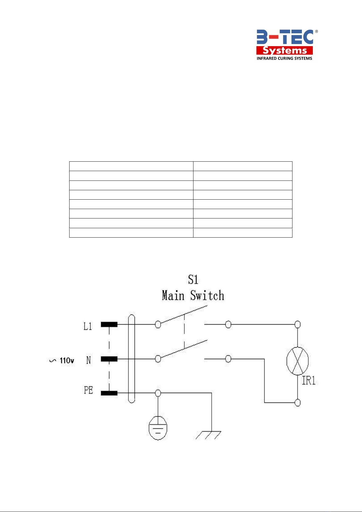
The machine should be well grounded for safety. The grounding device should be
connected to the proper output port under correct direction. Unauthorized alteration or
change of output port is strictly prohibited. Use of any outlet converter is also disallowed.
If you are ever uncertain, please find a professional electrician to check whether the
grounding is correct. Please make sure the machine is well grounded to avoid electric
shock.
If the lamp / tube fails to work after starting, it may be caused by a loosened outlet plug.
In such a case, just switch off the machine and check that plug is secure in the socket in
the connection box.
Replace any chaffed or damaged cables / wires immediately to avoid the possibility of
electric shock.
Don’t misuse the electric cable. Do not drag the machine with the power cable or pull the
power plug. Keep the power cable away from hot, oily or sharp objects.
Should the power cable become damaged, ask the manufacturer, service provider or a
professional to replace it to reduce the risk of injury / damage.
2.3 Maintenance and Care
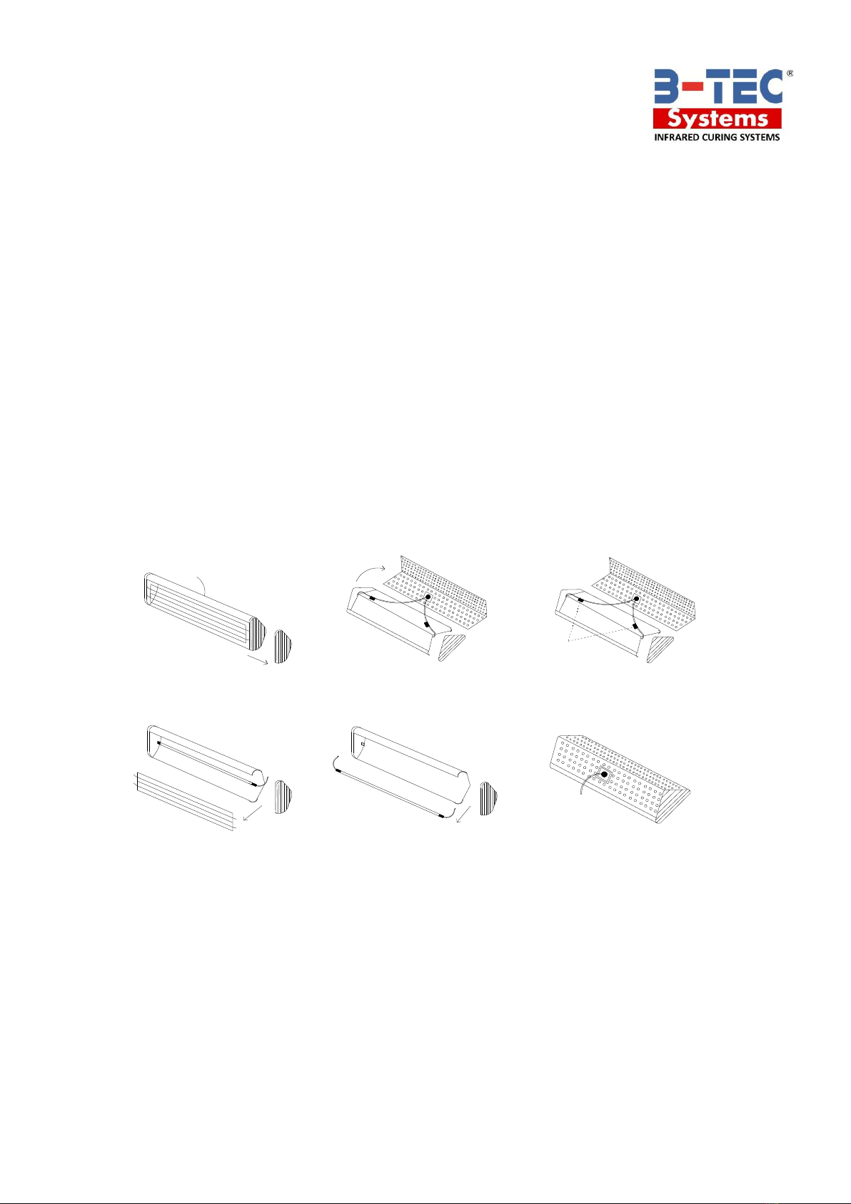
Regular cleaning of tubes and reflectors should be done by using a piece of soft cloth or
cotton with IPA, alcohol or mentholated spirits (Note: cleaning must only be conducted
after the machine is disconnected from the power supply and has cooled down if
necessary). Allow 15 minutes for the solvent to dissipate before switching the unit back
on.
The device should be protected by a 15-Amp-fuse.
For replacement lamps / tubes, contact your distributor.
2.4 More Information
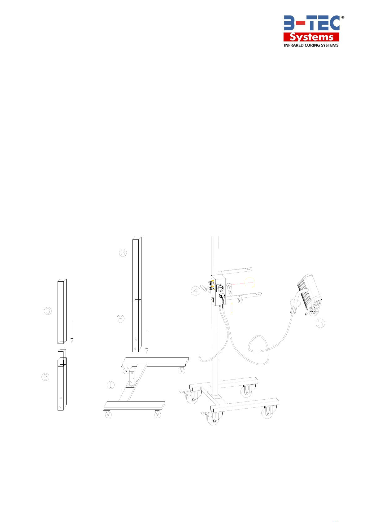
Always turn the unit off before moving, especially over rough surfaces.
Do not use the equipment in damp or wet locations.

6
3. Technical Description of the Machine
1. The infrared head has multiple angle adjustment.
2. The infrared head can be used stand mounted, or as a hand-held, offering great
flexibility.
3. The head height is adjustable up to an average vehicles glass line.
4. 2 x Electronic timers are incorporated to regulate the bake cycles, half power and full
bake.
3.1 Technical Information
3.2 Wiring Diagram
Input current
10 A
Input voltage
110 V - 60 Hz (1PH)
Short wave quartz halogen infrared tube
1 x 500 W
Max. power
500 W
Range of time
2 x 35 min
Baking area
16” x 12” inches
Max baking time
1 - 35 min
Dimension: (W x H x L)
24” x 61” x 24” inches

7
3.3 Spare Parts
IR-B01 Parts List
S/N
Name of Parts
Item #
S/N
Name of Parts
Item #
1
Front Wheel
B01-1
13
Tube
B01-16
2
Rear Wheel
B01-2
14
Small Reflector
Panel
B01-14
3
Pedestal
B01-3
15
Protective grill
B01-15
4
Square-tube Column
B01-4
16
Large Reflector
Panel
B01-8
5
U-Shape Support
B01-5
17
Bent Plate with
Handle
B01-17
6
Control Box
B01-6
18
Side Panel of Emitter
B03-19
7
Power-Connection
B01-7
19
Power-Button
B01-19
8
Handle big
B03-11
20
Handle
B01-20
9
Transformer 220V/6W
B01-9
21
Power cord
B01-21
10
Relays 10A
B03-30
22
Heat Dissipating
Plate
B01-22
11
Lid Control Box
B01-11
23
Locking Ring
B01-23
12
Bent Plate
B01-12
1
3
4
2
12
13
14
15
16
17
18
19
20
21
17
22
18
19
20
21
7
6
5
8
Control box
9
10
11
6
7
23
7
6
5
8
B-TEC Systems reserves the right to make technical changes without notice.

8
4. Assembly / Installation
1. Insert the upper section ③of the vertical bar into the lower section ②.
2. Take out the pedestal ①, insert the vertical bar into the pedestal ①and fasten the
screws.
3. Fit the lamp bracket ④onto the vertical bar.
4. Attach infrared head (5) facing forward and tighten handle.
5. Attach the power wire.
6. Important: Remove the sticker from the protection cover.
7. Important: Take out the red foam cubes behind the tube.
Notes:
Power supply: 10Amp, 1 PH 110V/60Hz
When adjusting the height of lamp cap, use your left hand to support the lamp bracket
and your right hand to loosen the handle of the locking ring ④for two turns, and then
move the bracket with two hands supporting the two ends of the lamp bracket. It is
best to use two hands to avoid any damage to the emitter / lamp.

9
5. Operating Instructions
1. Move the unit and choose the optimal distance between emitter and car body. The
optimal distance 12” to 14” inches.
2. Adjust the direction of the emitters. They should be aligned parallel to the car body.
3. Adjust the timer button (1) to set half power / flash baking time.
4. Adjust the timer button (2) to set full bake / continuous time.
5. Turn on the power switch (3).
6. The machine stops automatically after the curing cycle has been completed. If you
want to continue using the unit, restart the machine after cutting off the power for 5
minutes.
7. If you don’t want to use the stand and prefer to use hand, connect the Infrared head
directly to the power supply and turn on the power switch. In that situation there are
no time limits, no automatic stops and no half power facility.
5.1 Curing Times
All curing times are supplied as a guide only.
Paint type
Flash off
Full bake (Minutes)
Filler/Stopper
---
5-7
Primer
---
6-8
Hi-build
---
10-12
Solid-color
---
11
Clear coat
---
12
Waterborne primer
---
8-10
Waterborne basecoat
---
5
Note: We suggest that when curing high build primers and dark colors. You move back to 18”
and add 5 minutes to the bake time. If possible consult B-TEC SYSTEMS or your distributor
for the availability of a paint curing data sheet for your paint brand.
1
2
POWER
30
35 MIN35 MIN
3030
35 MIN
15 20
2525
20
1515 20
25
5
0
1010
0
55
0
10
CONTINUOUS
FLASH
35 MIN
3030
35 MIN35 MIN
30
0
55
00
5
25
20
10
1515
10
20
2525
20
10
15
3

10
6. Replacement of Emitter Lamp Tube
Un-plug from the power supply, before replacing the infrared emitter / tube.
1. Remove the side panel.
2. Release the radiating panel.
3. Loosen the two leads in the lamp and remove them.
4. Remove the protective grill in front of the emitter.
5. Take out the defective emitter and fit the new emitter after checking that the part you
purchased is correct. Ensure that you attach the wires correctly.
6. Install the protective grill, radiating panel and the side panel.
Use a piece of soft cloth or cotton to clean the reflector panel and the emitter with alcohol.
Cleaning must be conducted after the machine is disconnected from the power source and
cooled down if necessary. Do not restart the equipment until all solvent / cleaning fluid
residue has evaporated. 15 minutes advised as the evaporation time.
Disconnect
the wires of the emitter
1
2
3
4
5
6

11
7. Troubleshooting
PROBLEM
POSSIBLE CAUSE
POSSIBLE SOLUTION
SOLVENT
POPPING
Unit too close to panel
Move unit further away
Insufficient flash off time
Increase flash off time
Paint system has a fast reducer
Use a standard or slow reducer
UNDER CURE
OR SOFTNESS
OF THE PAINT
FILM
Unit too far away
Move unit closer
Insufficient bake time
Increase full bake time
Excessive film weight
Apply lighter coats
SOFTNESS ON
EDGES OF
REPAIR
Repair too large for I.R. unit
Split area into two, move unit for
2nd application. If flash off is
used, it will not be necessary on
secondapplication
DIFFICULTY IN
POLISHING
OUT DIRT NIBS
Too long on bake cycle
Reduce cure time
Unit too close to panel
Move unit further away
UNEVEN CURE
IR cassettes not shaped to
contours of repair
Adjust IR cassettes for even heat
distribution
For optimal baking performance, we recommend that users should obtain either B-TEC
SYSTEMS paint curing data, or consult the paint companies’ recommendations. A general
guide is supplied on page 9.
IF IN ANY DOUBT ABOUT ASSEMBLY OR OPERATION OF THE
UNIT PLEASE DO NOT HESITATE TO CONTACT YOUR
DISTRIBUTOR OR THE B-TEC SYSTEMS SERVICE DEPARTMENT
AT (480) 621-5304.
Above specifications and diagrams are subject to revision. B-TEC Systems reserves the right
to make any changes without notification.
Table of contents
Other B-TEC Dryer manuals