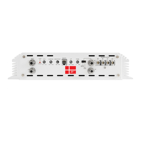
Connect preamp signal cables from
OUTPUT
Output RCA for signal routing to another ampl ifi e r.
POWER & PROTECTION INDICATOR
Protect LED, RED-lit shows general malfunction,
faulty connection or thermal protection
GAIN ( 6V ~ 0.2V )
Matching the output voltage of the headunit' s
SUBSONIC FILTER ( 10Hz ~ 50Hz @ 24dB/O ct )
Adjusts the subsonic cut off point to eliminat e low
frequencies.
V a r i a b l e b a s s b o o s t f r o m 0 - 9 d B @ 4 5 H z
R E M O T E L E V E L C O N T R O L P O R T
C o n n e c t i o n o f e x t e r n a l l e v e l c o n t r o l .
L O W P A S S F I L T E R ( 3 5 H z ~ 2 5 0 H z @ 2 4 d B / O c t )
A d j u s t s t h e c u t o f f p o i n t f o r t h e l o w p a s s f i l t e r .
P H A S E C O N T R O L
V a r i a b l e p h a s e a d j u s t m e n t f r o m 0 - 1 8 0 d e g r e e s .
3. CONTROL & CONNECTION
INPUT B A S S B O O S T
Power Green, Green-lit shows correct operatio n
3
For connection to the positive terminal of the
battery (+12). Due to the performance of theM12
0 gauge cable is required.
Due to the performance of the M12 0 gauge cable
Using the wrong gauge can lead to malfunction.
is required. SPEAKER OU T P U T S
+12V ( POWER CONNECTION ) Mi ni mu m s pe a ke r c a b l e i s 1 2 g a u g e .
M12
minimum impedance if used in 2ch mode is 1 ohm.
M12
4. INSTALLATION
If you choose to install the M12 series by yourself, please read the owner's manual carefully.
Before you start your installation, please take all steps into consideration. Otherwise, please go to
www.b2-audio.com for authorized distributors or contact us directly for support.
4-1. MOUNTING PREPARATION
Disconnect the negative ( ) battery cable before mounting B2 series or making any connections.
Check the battery and alternator ground ( ) connections.
Make sure they are properly connected and free of corrosion. Before selecting a mounting location
for the amplifier, please take cooling and safety into consideration.
B2 amplifiers have been designed with a good heat radiation heatsink to avoid excessive heat
from the amplifier circuitry. For optimum heat radiation performance, it is recommended to
find a mounting location that allows for vertical installation of the heat sink fins.
any accidentIal damage to the amplifier or the audio system.
M12
For connection to the chassi's ground Connect to switched +12V with trigger from Head Unit
headunit to RCA Input of
GND ( GROUND CONNECTION ) REM (REMOTE CONNECTION )
RCA line-outs toM12 input section.
The am pl if i er's c o n n e c ti o n t o the l o u d s p e a k e r s .
minimum impedance if used as a single unit is 2 ohm.
