JJ
JJ
J 8
Spare Part List
Legend
EU=230Vac Europe Version
US=115Vac U.S. Version
B=Black Gloss Finish
M=Mahogany Finish
BM=Briar Mahogany Finish
Baldwin =Baldwin version
Bachmann =Bachmann version
Code Description
Optional Accessories
130301 2mt Midi Cable
Accessories
271235 Owner’s Manual (Bachmann)(All Languages)
271292 Owner’s Manual (Baldwin)(English)
130274 Mains Cable (EU)
130276 Mains Cable (US)
970297 Pianist’s Bench (B)
970319 Pianist’s Bench (M)
970381 Pianist’s Bench (MB)
190193 *Hexagonal Rod Spanner
150618 *Thumbscrew
120523 *M 6 Black Grower Washer
120456 *M 6x1.5mm Black Washer
120070 *M 6x20mm Black Screw
Legs & Pedals
800047 Leg Assembly (B)
320818 *Caster
260248 *Leg (B)
720430 Pedals Assembly (B)
720467 *Triple Pedal Assembly
810168 **Reed Switch Board (Pcb#310272)
770742 **Pedals Cable
500063 **Mechanical Parts
340105 ***Plastic Support
171261 *** Chassis Support
170880 ***Screen Panel
170875 *** Right Pedal
170874 ***Left Pedal
170873 *** Centre Pedal
170777 ***Pedal Return Spring
340506 **Cable Clamping
340500 **Potentiometer Lever
340499 **Actuating Lever
340274 **Pedal Rubber
210016 **1x10mm Adhesive Black Felt (specify mt)
190181 **Pedals Clog
190178 **Permanent Magnet
190015 **Adhesive Rubber Foot
171264 **Lever Washer
171263 **Potentiometer Return Spring
171262 **Potentiometer Support
070556 **20K Lin (90deg. Stroke) Potentiometer
660121 *Pedals Stand (B)
260249 *Pedals Top Cover (B)
210042 *2x10mm Adhesive Spik (specify mt)
210021 *1x15mm Adhesive Red Felt (specify mt)
170858 *Pedals Brace
Cabinet Assembly
660588 Speaker Grid
660406 Music Stand Stop Bar
660405 Heatsink Grid
324642 Brassed Pin Closer
324614 Brassed Washer Art.759
324410 Hinge with Removable Pin between Cover and Cabinet
324408 Hinge between Front and Rear Covers
324405 Hinge between Front and Top Keyb. Covers, between Music
Stand and Cabinet
323070 9.5X3.8mm Bumpon Rubber
323069 11.1X5mm Bumpon Rubber
210074 Speaker Cloth
210018 1x5mm Adhesive Red Felt (specify mt)
210016 1x10mm Adhesive Black Felt (specify mt)
171672 Dual Hinge for Cover Sticks
171624 Hinge between Keyb. Cover and Cabinet
340116 Adhesive Clamp For Pedals Cable
340115 Adhesive Flat Cable Fixing
340075 Nylon Board Spacer
229015 8ohm 1" Dome Tweeter Speaker
220118 8ohm 8" Woofer Speaker
220117 8ohm 5" Woofer Speaker
210242 Filler for Speaker Box (Specify m²)
340075 Nylon Board Spacer
020493 100n 250Vac MKP EMI Capacitor “Siemens”
Wooden Parts
261769 Keyboard Cover (B)(specify Bachmann or Baldwin)
262066 Keyboard Cover (M)(specify Bachmann or Baldwin)
262067 Keyboard Cover (MB)(specify Bachmann or Baldwin)
261816 Cabinet Cover Short Stick (B)
262080 Cabinet Cover Short Stick (M)
262081 Cabinet Cover Short Stick (MB)
261755 Cabinet Cover Long Stick (B)
262062 Cabinet Cover Long Stick (M)
262063 Cabinet Cover Long Stick (MB)
261783 Stop Strip for Music Stand (B)
262078 Stop Strip for Music Stand (M)
262079 Stop Strip for Music Stand (MB)
261782 Left Shelf for Music Stand (B)
262076 Left Shelf for Music Stand (M)
262077 Left Shelf for Music Stand (MB)
261781 Right Shelf for Music Stand (B)
262074 Right Shelf for Music Stand (M)
262075 Right Shelf for Music Stand (MB)
261780 Right Keyboard Cheek Block (B)
262072 Right Keyboard Cheek Block (M)
262073 Right Keyboard Cheek Block (MB)
261779 Left Keyboard Cheek Block (B)
262070 Left Keyboard Cheek Block (M)
262071 Left Keyboard Cheek Block (MB)
261774 Right Mid-Range Box
261773 Woofer Box
261772 Left Mid-Range Box
261771 Cloth Panel
261770 Front Panel (B)
262068 Front Panel (M)
262069 Front Panel (MB)
261758 Revolving Keyboard Cover (B)
262064 Revolving Keyboard Cover (M)
262065 Revolving Keyboard Cover (MB)
261754 Centre Shelf for Music Stand (B)
262060 Centre Shelf for Music Stand (M)
262061 Centre Shelf for Music Stand (MB)
261753 Music Stand (B)
262058 Music Stand (M)
262059 Music Stand (MB)
261752 Keyboard Cross-Bar (B)
262058 Keyboard Cross-Bar (M)
262059 Keyboard Cross-Bar (MB)
261751 Rear Cabinet Cover (B)
262054 Rear Cabinet Cover (M)
262055 Rear Cabinet Cover (MB)
261750 Front Cabinet Cover (B)
262052 Front Cabinet Cover (M)
262053 Front Cabinet Cover (MB)
Transformer
730453 Transformer Assembly 230Vac (EU)
730470 Transformer Assembly 115Vac (US)
340329 *Rubber Bush
230130 *Transformer 230Vac 220W (EU)
230131 *Transformer 115Vac 220W (US)
190133 *Lateroid Insulator For Screw Block
140036 *Screw Block (specify contacts)
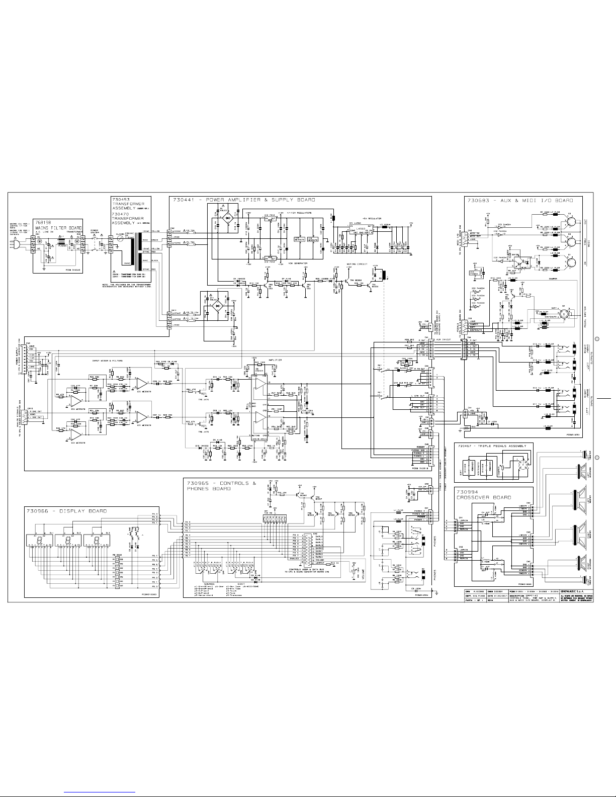
Power Amplifier & Supply Board
730441 Power Amplifier & Supply Board (Pcb#310518)
230527 *BL02RN2-R62 EMI Coil For Signal
230524 *100uH Switching Coil
171342 *Left Holding Board
171341 *Right Holding Board
141010 *4 Contacts Vert Female Connector
140917 *2 Contacts Vert Male Connector
140352 *9 Contacts Hor Male Connector
140351 *6 Contacts Hor Male Connector
140323 *6 Contacts Vert Male Connector
140010 *3 Contacts P=10 Vert Terminal Block
110304 *Relay 12V / 2 Switch 5A 250V
110119 *Fuse Clip 10A max (EU) (US)
100919 *MC33078 Dual LN Operational Amplifier
100900 *L4960 5-40V 2.5A Switching Regulator
100045 *7812 +12V 1A Voltage Regulator
100043 *7912 -12V 1A Voltage Regulator
100039 *STK4151V 2x40W Hybrid Amplifier
090856 *J176 TO92 P-Channel J-Fet Transistor
090183 *BC550 TO92 LN Npn Transistor
080605 *KBL02 4A 200V Rectifier Diode Bridge
080171 *FE6B 6A 100V Fast Recovery Diode
080156 *1N4002 1A 100V Rectifier Diode
080103 *1N4148 100mA 75V Signal Diode
030950 *470u 16V 20% Low Esr Vert Electrolytic Capacitor
030880 *10000uF 25V Snap-In Electrolytic Capacitor
030721 *1000u 25V 20% Vert Electrolytic Capacitor
030555 *4700u 50V 20% Snap-In Electrolytic Capacitor
030486 *100u 50V 20% Vert Electrolytic Capacitor
110010 T2A Fuse 5x20mm (EU)
110003 T3.15A Fuse 5x20mm (EU)
110083 T2A Fuse 6.3x32mm (US)
110061 T3.15A Fuse 6.3x32mm (US)
Aux & Midi I/O Assembly
730682 Aux & Midi I/O Assembly
730683 *Aux & Midi I/O Board (Pcb#310551)
230569 **FL5R200PNT EMI Coil For Signal
230527 **BL02RN2-R62 EMI Coil For Signal
141010 **4 Contacts Vert Female Connector
140917 **2 Contacts Vert Male Connector
140351 **6 Contacts Hor Male Connector
140217 **Jack Slim Horizontal S-F Socket
140216 **6 Poles Din Horizontal Female Socket
140212 **5 Poles Din Horizontal Female Socket
100602 **74HC04 Hex Inverter
100035 **6N138 Optocoupler
090194 **BC560 TO92 LN Pnp Transistor
080103 **1N4148 100mA 75V Signal Diode
652855 *Sockets Box
210018 *1x5mm Adhesive Red Felt (specify mt)
171329 *Support for Outputs Panel
150474 *Plug For Unused Hole
Cross-Over Board
730994 Cross-Over Board (Pcb#310606)
230533 *0.45mH 1mm Crossover Coil
141101 *4 Contacts Vert Male Connector
030171 *4u7 63V 20% Axial Elect. Bipolar Capacitor
Keyboard Assembly
720563 Keyboard Assembly
840802 *20 Wires 55cm Length Flat Cable
840795 *4 Wires 40cm Length Crimp Terminal Cable
761148 *Keyboard Interface Board (Pcb#310577)
751148 **Keyboard Interface Board (Pcb#310577)
141018 ***20 Contacts Vert Female Connector
141011 ***6 Contacts Vert Female Connector
140918 ***2 Contacts Hor Male Connector
140874 ***Single In Line Vert Male Strip (specify contacts)
140872 ***4 Contatcs Hor Male Connector
104019 ***ST24W02 SOIC 2Kbit Serial Access EEprom
100626 *** 74HC4053 3x2ch Analog Multiplexer
100619 ***74HC32 Quad 2-Input Or Gate
100610 ***74HC245 Octal Bus Transceiver
100066 ***LM317 1.2-37V 1.5A Adjustable Regulator
080156 ***1N4002 1A 100V Rectifier Diode
010726 ***19.2MHz Ceramic Resonator With Capacitors
010662 ***220p 10% 50V X8 Cap Array
550645 **H8-329 Cpu “VALIS” programmed for optical keyboard
140877 **Jumper For Contacts Strip (p=2.54mm)
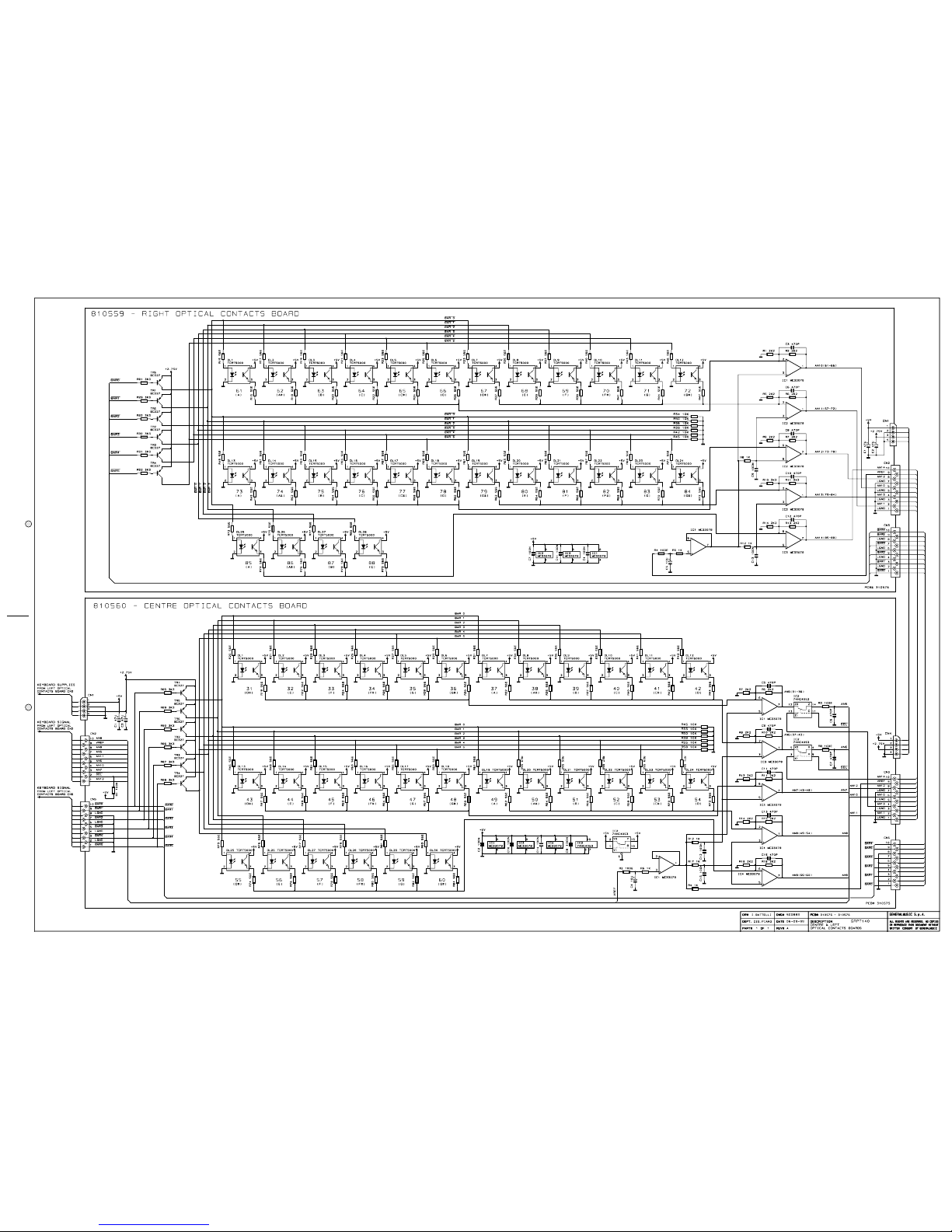
720525 *Optical Contacts Assembly
841097 **10 Wires 12,5cm Length Flat Cable
841096 **4 Wires 7,5cm Length Flat Cable
840823 **10 Wires 10cm Length Flat Cable
810561 **Left Optical Contacts Board (Pcb#310574)
141018 ***20 Contacts Vert Female Connector
141013 ***10 Contacts Vert Female Connector
140872 ***4 Contatcs Hor Male Connector
100919 ***MC33078 Dual LN Operational Amplifier
100626 *** 74HC4053 3x2ch Analog Multiplexer
090153 ***BC327 TO92 Pnp Transistor
080900 ***TCRT5000 Optoelectronic Reflex Sensor
810560 **Centre Optical Contacts Board (Pcb#310575)
141013 ***10 Contacts Vert Female Connector
140872 ***4 Contatcs Hor Male Connector
100919 ***MC33078 Dual LN Operational Amplifier
100626 *** 74HC4053 3x2ch Analog Multiplexer
090153 ***BC327 TO92 Pnp Transistor
080900 ***TCRT5000 Optoelectronic Reflex Sensor
810559 **Right Optical Contacts Board (Pcb#310576)
141013 ***10 Contacts Vert Female Connector
140872 ***4 Contatcs Hor Male Connector
100919 ***MC33078 Dual LN Operational Amplifier
090153 ***BC327 TO92 Pnp Transistor
080900 ***TCRT5000 Optoelectronic Reflex Sensor
660579 **Optical Contacts Board Support
340093 **Board Spacer
509007 *Keyboard LANGER Mod. 113/117
508029 *Mechanic DETOA for RPT114
340075 *Nylon Board Spacer
Controls Panel Assembly
731008 Controls Panel Assembly
840764 *Ground Cable 10cm Length
768198 *Mains Filter Board (Pcb#310643)
230565 **2.5mH 250V 3A AC Line Filter
140010 **3 Contacts P=10 Vert Terminal Block
020493 **100n 250Vac MKP EMI Capacitor “Siemens”
010545 **4n7 250V Ceramic Capacitor (Iec-Ul-Csa)
730965 *Controls & Phones Board (Pcb#310584)
730966 **Display Board (Pcb#310583)
140890 ***4 Contacts Hor Male Single-Strip
140529 ***Microswitch 12V 50mA 0.25mm
080717 *** HDN1105 7 Segments Display
080103 *** 1N4148 100mA 75V Signal Diode
230569 **FL5R200PNT EMI Coil For Signal
141018 **20 Contacts Vert Female Connector
140917 **2 Contacts Vert Male Connector
140877 **Jumper For Contacts Strip (p=2.54mm)
140874 **Single In Line Vert Male Strip (specify contacts)
140873 **4 Contacts Vert Male Connector
140217 **Jack Slim Horizontal S-F Socket
140207 **Jack Horizontal F Socket (with dual switch)
110321 **2sw 6pos Rotary Switch
090194 **BC560 TO92 LN Pnp Transistor
080103 **1N4148 100mA 75V Signal Diode
074699 **50KB C.C. 11mm Horr. Rotary Po
660595 *Controls Box
652238 *2 Keys <+ -> Rubber Pad
347360 *Knob
340882 *Button Spacer
340120 *Plexiglass Display Screen
340093 *Board Spacer
110614 *Mains Socket
110285 *Power Switch
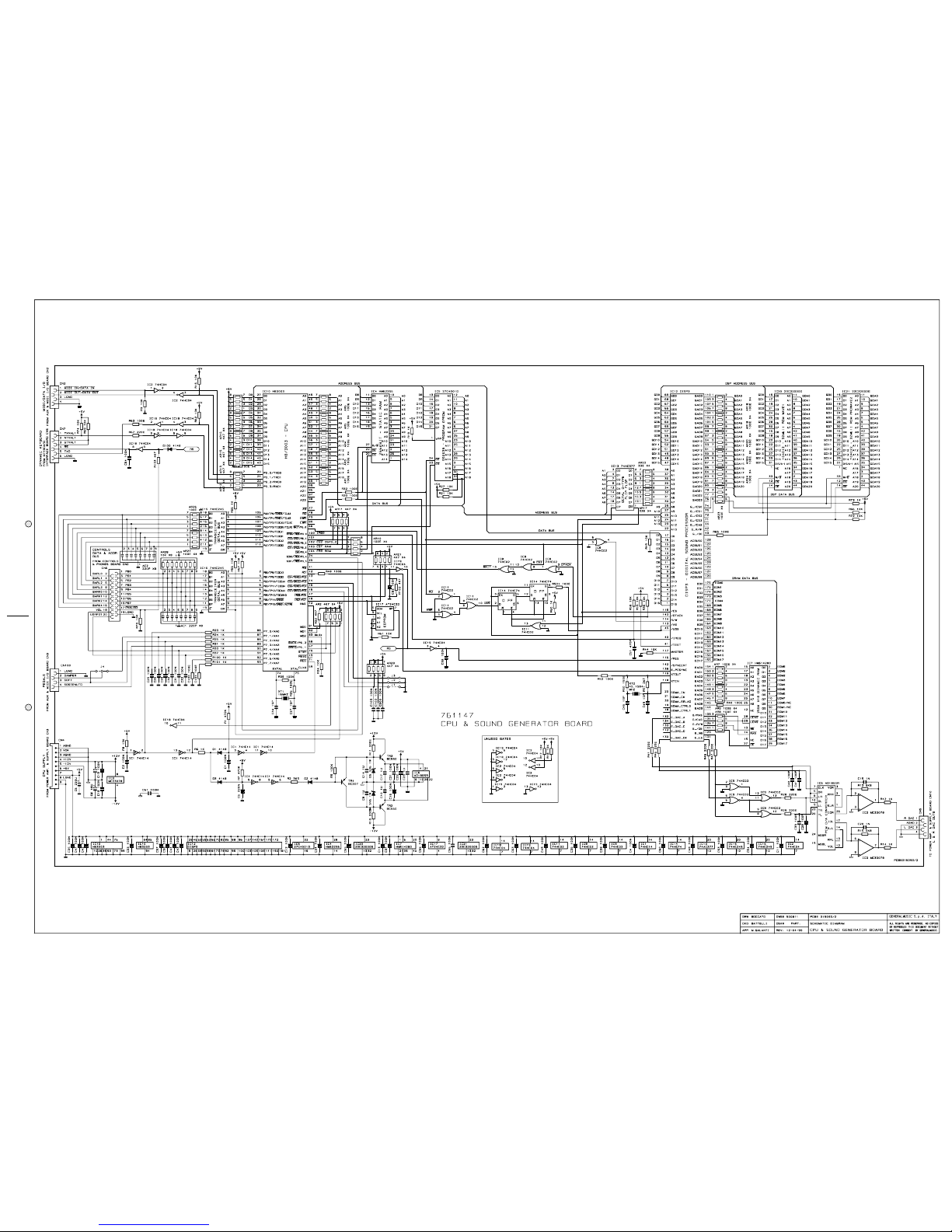
Cpu & Sound Generator Board
761147 *Cpu & Sound Generator Board (Pcb#315093)
141018 **20 Contacts Vert Female Connector
141011 **6 Contacts Vert Female Connector
141010 **4 Contacts Vert Female Connector
140889 **Dual In Line Vert Male Strip (specify contacts)
140874 **Single In Line Vert Male Strip (specify contacts)
140352 **9 Contacts Hor Male Connector
106001 **MC33078P SOIC Dual Low Noise Op. Amp.
105009 **DISP3 QFP Digital Sound Processor (Hitachi)
105006 **HD6413003F16 QFP Cpu
104022 **23C32000G SOP 32Mbit Rom “ProWave2”
104021 **AT24C32N SOIC 32Kbit Serial Access EEprom
104020 **KM62256CLG SOP 256Kbit SRam Ta=55nS
104012 **23C32000G SOP 32Mbit Rom “Wave1”
104010 **HM514280AJ 4M5bit Dram Ta=70nS
103010 **74HC04D SOIC Hex Inverter
103009 **74HC02D SOIC Quad 2-In Nor Gate
103007 **74HC74D SOIC Dual Flip-Flop
103004 **AD1865R SOP 18bit D/A Converter
103002 **74HC245DW SOIC Octal Bus Transceiver
103000 **74HC14D Soic Hex Inverter Schmitt Trigger
101501 **74AC377DW SOIC Octal Dtype Flip Flop
090194 **BC560 TO92 LN Pnp Transistor
090183 **BC550 TO92 LN Npn Transistor
081000 **PMLL4148 Smd 100mA 75V Signal Diode
080241 **5V6 1W 5% Zener Diode
010727 **45.1584MHz Quartz Resonator
010704 **16MHz Quartz Resonator
010662 **220p 10% 50V X8 Cap Array
550638 **27C4001D 4MBit “Program” Eprom
140877 **Jumper For Contacts Strip (p=2.54mm)
Wiring Connections
770826 Mains Cables Assembly
770827 Cross-Over Cables Assembly
770825 Bass Box Cables Assembly
770824 Left Speaker Box Cables Assembly
770823 Right Speaker Box Cables Assembly
770822 Cables Assembly
841162 20 Wires 120cm Length Flat Cable
841160 20 Wires 50cm Length Flat Cable
841011 6 Wires 65cm Length Flat Cable
840810 4 Wires 30cm Length Flat Cable
840754 4 Wires 60cm Length Flat Cable
840208 9 Wires 30cm Length Flat Cable
Note:
Each spare part is single quantity unless otherwise specified.
Asterisk prefix explanation:
Omitted = First level spare part.
One asterisk = Second level, part of previous listed first level part.
Two asterisk = Third level, part of previous listed second level part.
Three asterisk= ............
Any request for not above mentioned part must encompass specific
description including:
1) Model name,
2) Section name,
3) Module code,
4) Reference name,
5) Quantity number.