o 10
Spare Parts List (RPT114)
Wooden Parts
710449 Wooden Parts (Black hi-gloss)
261683 * Shutter Rear Panel
261675 * Pedals Box
261674 * Speaker Rear Panel
261671 * Lower Front Panel
261670 * Right Foot
261669 * Left Foot
261666 * Cover
261665 * Cross Bar
261662 * Upper Front Panel
261661 * Keyboard Panel
261658 * Right Side
261657 * Left Side
261564 * Music Stand
261397 * Sliding Cover
261390 * Keyboard Bar
261389 * Keyboard Cover
710451 Wooden Parts (Black)
261689 * Right Food
261688 * Left Food
261683 * Shutter Rear Panel
261681 * Upper Front Panel
261680 * Pedals Box
261677 * Right Side
261676 * Left Side
261674 * Speaker Rear Panel
261672 * Lower Front Panel
261667 * Cover
261665 * Cross Bar
261661 * Keyboard Panel
261633 * Music Stand
261628 * Revolving Cover
261622 * Keyboard Bar
261621 * Keyboard Cover
710452 Wooden Parts (Walnut)
261708 * Rear Panel
261706 * Right Foot
261705 * Left Food
261698 * Upper Front Panel
261696 * Upper Right Side
261695 * Lower Left Side
261694 * Right Side
261693 * Left Side
261684 * Shutter Rear Panel
261682 * Pedal Box
261673 * Lower Front Panel
261668 * Cover
261665 * Cross Bar
261661 * Keyboard Panel
261654 * Music Stand
261648 * Slider Cover
261642 * Keyboard Bar
261641 * Keyboard Cover
Various
340159 3M Dual Lock Fastening (Specify mt)
340042 Plastic Handle
324407 Double Hinge (659 item)
324405 Hinge (661 item)
323069 Transparent Beating Rubber
210074 Black Acoustic Cloth
171331 Cover Left Fixing Bar
171330 Cover Right Fixing Bar
170389 Rear Cover Support Square
657241 Black tube
660405 Heat Sink Protection Grid
220115 8E Midrange Speaker
220114 8E Woofer
271202 Users Manual
140036 Screw Block (specify contacts)
030348 47UF 20% 100V Electrolitic Capacitor
660567 Controls & Outputs Box
652239 2 Keys <<>> Rubber Pad
347360 Gray/Black Knob
110285 Power Switch
Brassed Pedals Assemblly
720408 Brassed Pedals Assemblly
810168 * Reed Switch Board (PCB#310272)
770717 * Connection Cable
500063 * Mechanical Parts
340105 ** Chassis Support
171261 ** Chassis Support
170880 ** Screen Panel
170875 ** Right Pedal
170874 ** Left Pedal
170873 ** Centre Pedal
170777 ** Pedal Return Spring
340500 * 3 Pedals Comand Lever
340499 * 3 Pedals Carring-out Lever
340274 * Pedal Rubber
210016 * 1x10mm Adhesive Black Felt (specify mt)
190181 * Pedals Clog
190178 * Permanent Magnet
190015 * Adhesive Rubber Foot
171263 * Pedals Spring
070556 * 20K Lin (90deg. Stroke) Potentiometer
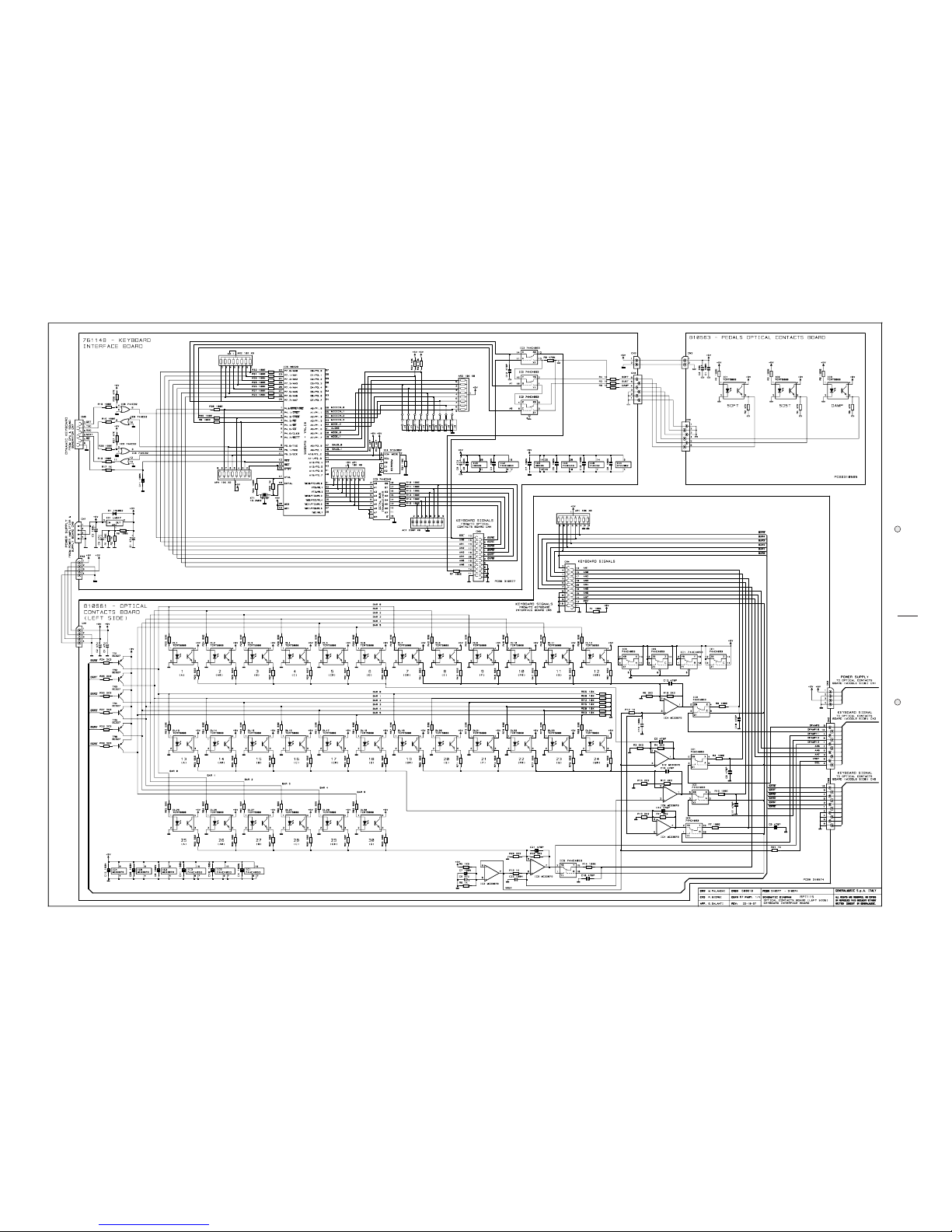
Mains Filter Board
767988 Mains Filter Board (PCB# 315014/2)
230568 * 10mH 250Vac 1A AC Line EMI Coil Siemens
140010 * 3 Contacts P=10 Vert Terminal Block
110113 * Fuse Clip 5x20mm 6A max (EU)
020493 * 100n 250Vac MKP EMI Capacitor Siemens
010545 * 4n7 250Vac
150021 * Cord Lock
130294 * Mains Cord (EU)
Transformer Assembly
230132 * Transformer 230Vac 130W
190133 * Lateroid Insulator For Screw Block
140036 * Screw Block (specify contacts)
110013 * T1.25A Fuse 5x20mm
110011 * T1A Fuse 5x20mm
110003 * T3.15A Fuse 5x20mm
020493 * 100n 250Vac MKP EMI Capacitor Siemens
CPU& Sound Generator Board
761146 CPU& Sound Generator Board (PCB#315093)
141012 * Con V F 8 C P=1.27 Mmatch Amp
141011 * 6 Contacts Vert Female Connector
141010 * 4 Contacts Vert Female Connector
140889 * Dual In Line Vert Male Strip (specify contacts)
140874 * Single In Line Vert Male Strip (specify contacts)
140352 * 9 Contacts Hor Male Connector
106001 * MC33078P Smd Dual LN J-Fet Operational Amp.
105009 * 50MHz DISP3
105006 * HD6413003F16 Cpu Smd F=16MHz
104020 * HM62256AFP-7T SOP Sram 256K Ta=70nS
104018 * 23C32000G SOP Rom 32Mbit Wave Rps
104010 * HM514280AJ SOJ Dram 4M5bit Ta=70nS
103010 * 74HC04D SOIC Hex Inverter
103009 * 74HC02D SOIC Quad 2-In Nor Gate
103007 * 74HC74D SOIC Dual Flip-Flop
103004 * AD1865R SOP 18bit D/A Converter
103000 * 74HC14D Soic Hex Inverter Schmitt Trigger
101501 * 74AC377DW SOIC Octal Dtype Flip Flop
090194 * BC560 TO92 LN Pnp Transistor
090183 * Bc550 To92 Ln Npn Transistor
081000 * PMLL4148 Smd 100mA 75V Signal Diode
080241 * 5V6 1W 5% Zener Diode
010727 * 45.1584MHz Quartz Resonator
010704 * 16MHz Quartz Resonator
010599 * 1u 50V -20+80% Ceramic Cap. Multilayer
550607 27C1001 1Mbit Program Eprom
140877 Jumper For Contacts Strip (p=2.54mm)
Power Amplifier & Supply Board
730675 Power Amplifier & Supply Board (PCB#310543)
141010 * 4 Contacts Vert Female Connector
140917 * 2 Contacts Vert Male Connector
140352 * 9 Contacts Hor Male Connector
140351 * 6 Contacts Hor Male Connector
140010 * 3 Contacts P=10 Vert Terminal Block
110119 * Fuse Clip 10A max (EU) (US)
100958 * TDA7265 Dual 25W Power Amplifier
100919 * MC33078 Dual LN J-Fet Operational Amp.
100059 * 7805 +5V 1A Voltage Regulator
100045 * 7812 +12V 1A Voltage Regulator
100043 * 7912 -12V 1A Voltage Regulator
090856 * J176 TO92 P-Channel J-Fet Transistor
090183 * Bc550 To92 Ln Npn Transistor
080605 * KBL02 4A 200V Bridge Rectifier Diode
080156 * 1N4002 1A 100V Rectifier Diode
080103 * 1N4148 100mA 75V Signal Diode
Controls & Outputs Board
730977 Controls & Outputs Board (PCB#310587)
230569 * FL5R200PNT EMI Coil For Signal
141012 * Con V F 8 C P=1.27 Mmatch Amp
141010 * 4 Contacts Vert Female Connector
140917 * 2 Contacts Vert Male Connector
140877 * Jumper For Contacts Strip (p=2.54mm)
140874 * Single In Line Vert Male Strip (specify contacts)
140529 * Microswitch 12V 50mA 0.25mm
140351 * 6 Contacts Hor Male Connector
140217 * Horizontal Jack Stereo Slim Socket
140216 * Horizontal Female 6 Poles Din Socket
140212 * Horizontal Female 5 Poles Din Socket
140207 * Horizontal Female Jack Socket
100035 * 6N138 Optocoupler
090194 * BC560 TO92 LN Pnp Transistor
090183 * Bc550 To92 Ln Npn Transistor
080705 * Led 3mm 60deg Diffused Red
080103 * 1N4148 100mA 75V Signal Diode
074699 * 50Kb C.C. 11mm Horr. Rotary Po
030245 * 10u 50V 20% Vert Electrolytic Capacitor
010595 * 100n 50V -20+80% Ceramic Cap. Multilayer
Keyboard Assembly
720543 Keyboard Assembly (TP10)
810552 * 39 Contacts Left Board For Dynamic Keyboard (PCB#310531)
340764 ** 3 Dual Contacts Rubber Strip
340211 ** 12 Dual Contact Rubber Strip
141018 ** 20 Contacts Vert Female Connector
141010 ** 4 Contacts Vert Female Connector
080103 ** 1N4148 100mA 75V Signal Diode
810551 * 49 Contacts Right Board For Dynamic Keyboard (PCB#310530)
340212 ** 13 Dual Contact Rubber Strip
340211 ** 12 Dual Contact Rubber Strip
141018 ** 20 Contacts Vert Female Connector
141010 ** 4 Contacts Vert Female Connector
080103 ** 1N4148 100mA 75V Signal Diode
760995 * Keyboard Interface Board (PCB#315024)
141018 ** 20 Contacts Vert Female Connector
141011 ** 6 Contacts Vert Female Connector
140918 ** 2 Contacts Hor Male Connector
100740 ** HD6433278 Cpu F=20MHz
100605 ** 74HC125 Quad 3-State Buffer
050493 ** Resistor Array 10K X4 1/8w 5%
050492 ** 10Kx8 1/8w 5% Resistor Array
050414 ** 2K2 X4 1/8w 5% Resistor Array
010726 ** 19.2MHz Ceramic Resonator With Cap.
010662 ** 220p 10% 50V X8 Cap Array
010661 ** 47p 10% 50V X8 Cap Array
171615 * Contacts Boards Support Panel
RPT114/O version Spare Parts List
Keyboard Interface Board
761148 Keyboard Interface Board (PCB#310577)
141018 * 20 Contacts Vert Female Connector
141011 * 6 Contacts Vert Female Connector
140918 * 2 Contacts Hor Male Connector
140874 * Single In Line Vert Male Strip (specify cont.)
140872 * 4 Contatcs Hor Male Connector
104019 * ST24W02 Smd 2Kbit Serial Access EEprom
100626 * 74HC4053 3x2ch Analog Multiplexer
100619 * 74HC32 Quad 2-Input Or Gate
100610 * 74HC245 Octal Bus Transceiver
100066 * LM317 1.2-37V 1.5A Adjustable Regulator
010726 * 19.2MHz Ceramic Resonator With Cap.
010662 * 220p 10% 50V X8 Cap Array
550645 IC MICRO H8/329 PROG.<VALIS-O RPT 115>
140877 Jumper For Contacts Strip (p=2.54mm)
Optical Contacts Assembly
720525 Optical Contacts Assembly
810561 * Optical Contacts B. (Left Side) (PCB#310574)
141018 ** 20 Contacts Vert Female Connector
141013 ** Con V F 10c P=1.27 Mmatch Amp
140872 ** 4 Contatcs Hor Male Connector
100919 ** MC33078 Dual LN J-Fet Operational Amp.
100626 ** 74HC4053 3x2ch Analog Multiplexer
090153 ** BC327 TO92 Pnp Transistor
080900 ** OPTOELECT. REFLEX SENSOR TCRT5000
810560 * Optical Contacts B. (Central Side) (PCB#310575)
141013 ** Con V F 10c P=1.27 Mmatch Amp
140872 ** 4 Contatcs Hor Male Connector
100919 ** MC33078 Dual LN J-Fet Operational Amp.
100626 ** 74HC4053 3x2ch Analog Multiplexer
090153 ** BC327 TO92 Pnp Transistor
080900 ** OPTOELECT. REFLEX SENSOR TCRT5000
810559 * Optical Contacts B. (Right Side) (PCB#310576)
141013 ** Con V F 10c P=1.27 Mmatch Amp
140872 ** 4 Contatcs Hor Male Connector
100919 ** MC33078 Dual LN J-Fet Operational Amp.
090153 ** BC327 TO92 Pnp Transistor
080900 ** OPTOELECT. REFLEX SENSOR TCRT5000
660579 * Optical Contacts Board Support
Note:
Each spare part is single quantity unless otherwise specified.
Asterisk prefix explanation:
Omitted = First level spare part.
One asterisk = Second level, part of previous listed first level part.
Two asterisk = Third level, part of previous listed second level part.
Three asterisk = ............
Any request for not above mentioned part must encompass specific description including:
1) Model name,
2) Section name,
3) Module code,
4) Reference name,
5) Quantity number.