BA_373-E45_05_DEF_MJ_2119
7 | 36W. Baelz & Sohn GmbH & Co. · Koepffstrasse 5 · 74076 Heilbronn · Germany · www.baelz.de Seite | Page
Motorized Linear Actuator baelz 373-E45
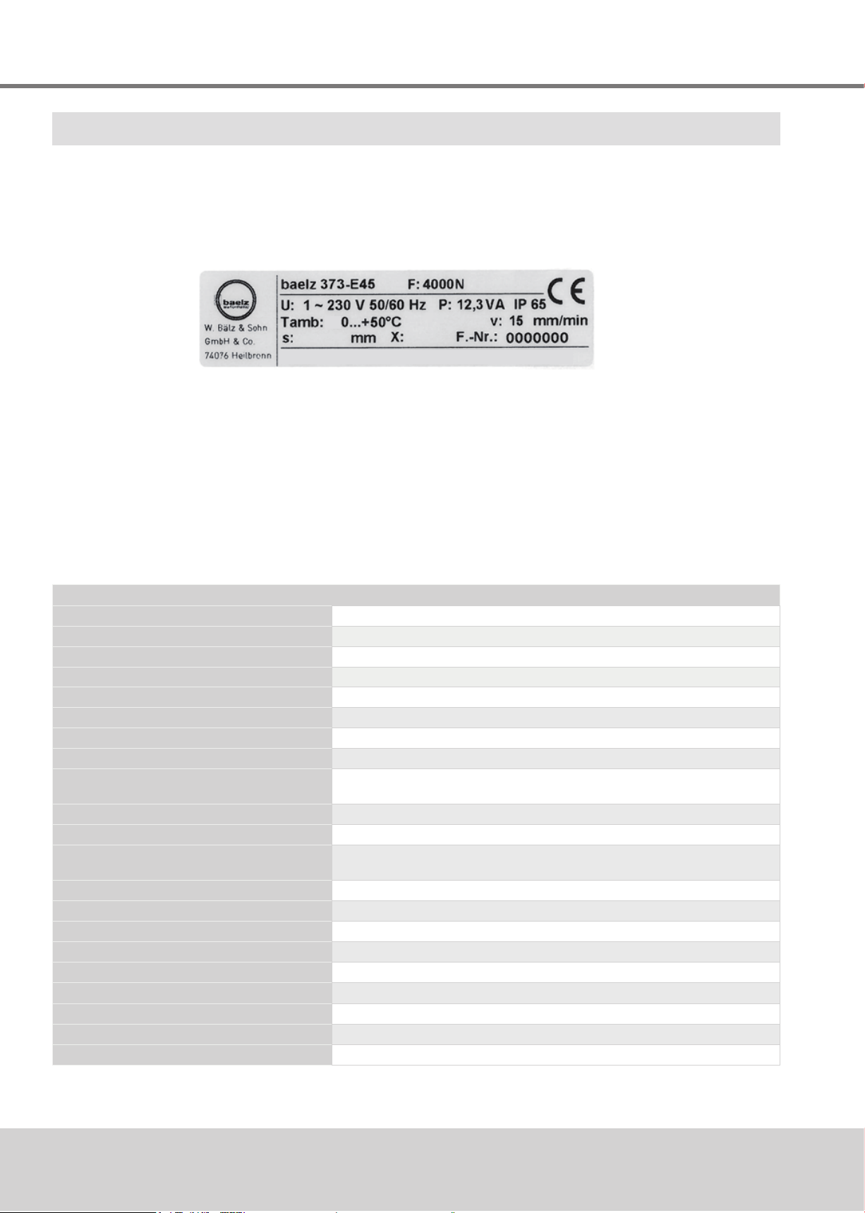
2.3 Type name
2.4 Accessories and options
Table 2. Options for Actuators
2EZ-Fg
Twoadditionallimitswitchesforsignallingendpositionsorintermediatepositions,freelyadjustable,
max.250VAC,ratingforresistiveloadmax.5A,forinductiveloadmax.3A
and
200Ω/1kΩ/5kΩpotentiometer,linearityerror≤0.5%,max.1.5W,contactcurrent30mA,stroke
reducedby[%ohmxactualstroke/44]mm,dependingonvalvestroke
7020A
Digitalpositionerforactuatorcontrol,selfadapting
1inputsignal:0(2)…10V,0(4)…20mAor(3-point)
2outputsignals:0(2)…10Vand0(4)…20mA
1digitalinput,2relaysforfeedbackonendorintermediatepositions,
InterfaceRS485ModbusRTU,incl.5kΩpotentiometer
Hzg Heatingresistorwiththermoswitchagainstmoisturewithautomatictemperatureregulation,
max.15Watts,supplyvoltage24,115,230V50/60Hz
baelz 373 - E45 - 40 - 15 - S21
motorizedlinearactuator actuatortype thrust positioningspeed yoketype
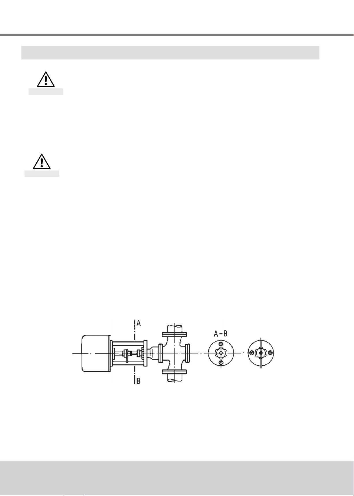
2.5 Operating conditions
Incaseofextremevariationsinambienttemperatureandhighhumiditylevels,installationofa
heatingresistorisrecommendedtominimisecondensationintheactuator.
Actuatorcoverswithsuppressionofthermalbridges(dualcovers)arerecommended.
● Connecttheheatingelement(HZG)asshowninthewiringdiagram.
● Putthedeviceintoserviceassoonasitisinstalled.
Theactuatorsaresuitableforinstallationinindustrialplantsandinwaterworksandpower
plantswithalowpollutantconcentration.
Foruseoutdoorsorinanenvironmentwithahighpollutantconcentration,suchasheavytrafc
areas,industrialareas(chemicalplants,sewageplants,etc.),coastalareasandtheopensea,
theactuatorsmusthaveexternalpartsmadeofnon-corrosivematerialandmustbeprovided
withaspecialcoating.
Whenusedoutdoors,theactuatormustbeprotectedwithanadditionalcoveragainst
●rain
● directsunlight
● strongdraughts
● dust
3. TRANSPORT AND STORAGE
Risk of injury caused by failure to observe safety regulations!
Caution
● Weartherequiredpersonalandotherprotectiveequipment.
● Protectthelinearactuatorfromimpact,shock,vibrationandsimilarinuences.
● Storethelinearactuator(orthecompleteactuator/valveassembly)inadryplace.
● Observethetransportandstoragetemperaturelimitsof-20to+60°C.