CONTENTImportant Notice
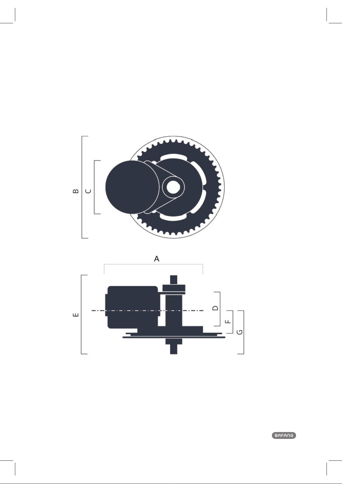
4For your Safety 5 61 Drive Unit (MM G32.1000) 71.1 Advantages 71.2 Scope of Application 71.3 Product Naming Protocol 7 1.4 Main Techinialc Parameters 81.5 92 System Installation 102.1 102.2 112.3 Display Installation (DP C10.UART)122.4 Auxiliary Keypad Installation132.5 Battery Rail Installation 152.6 External Speed Sensor Installation SR SD02.01
152.7 Drive Unit Installation 183 System Cabling 253.1 Connection of the Battery Cable to the Drive unit 253.2 Connection of the Speed Sensor to the Drive unit 253.3 Connection of the EB-BUS to the Drive unti
263.4 Connection of the Headlight Cable to the Drive Unit 263.5 Connection of the Headlight to the Drive Unit
274.4 Battery Health Indication
414.5 Battery Installation
425 Display (DP C10.UART) 436.1 Specifications and Parameters of the Display 436.2 Appearance and Dimensions 436.3 Function Overview and Key Definations
446.4Normal Operation
466.5 Parameter Setting 486.6 Error Code Definitions556 List of Materials567.1 Display Unit-DP C10.UART
567.2 Drive Unit -MM G32.1000
567.3 Cables587 Service and Warranty Policy 59Notes 60CONTENTNoteDrive Unit Structure and DimensionsList of Tools to be usedComponent Names4 Battery (Optional) 394.1Using the Battery Properly404.2 Charging the Battery 404.3 Battery Capacity Display
41