9
d) The hot surface ignition system, all related switches, indicator light and fuse, are all connected through
the 6 ft (1830 mm) power supply cord. The power supply cord must be plugged into a properly grounded
three-prongreceptacle.
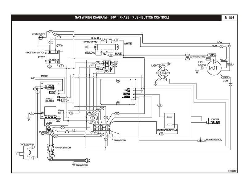
e) A wiring diagram may be found behind the service panel on the left side of the unit and also in this
manual.
f) The ovens should not be installed on the same line with space heaters, boilers or other gas equipment
withhighintermittentdemand.
g) Use a pipe joint compound that is resistant to the action of liquefied petroleum gases when making gas
connections.
h) For Propane gas, use a least½ pipeor tubingwith a 5/8 inside diameter. For Naturalgas, use ¾ pipe.
i) The appliance must be isolated from the gas supply piping system by closing its manual shut-off valve
during any pressure testing of the gas supply piping system at test pressures equal to or less than ½ psig
(3.45kpa).
j) The appliance and its shut-off valve must be disconnected from the gas supply piping system during any
pressure testing of that systemat test pressures in excess of ½ psig (3.45 kpa).
k) The gas pressure regulators are part of the combination valves and are adjusted to yield a pressure of
3.5 water column (9 mbar) for Natural Gas. If the oven has been ordered for use on Propane Gas, the
pressure regulators in the combination valves are preset at the factor to yield a pressure of 10 water
column(25mbar).
l) Aseparate shut-off valve for each oven must be provided. It should be as close as possible to the place
where the gas line enters theoven. It must be located whereit is easily and quickly accessible.
m) When stacking with anothertype of oven, two (2) shut-off valves, one for each of the two ovens, must be
provided.
After the gas supply has been connected, it is extremely important to check all the piping for leaks. Use a
soap and water solution or a product made expressly for this purpose. Do not use matches, candles or a
flame etc. to check leaks sincethese methods are extremely dangerous.
The purpose of the safety pilot system is to lock the gas supply to the burner at the combination valve, if for
any reason the pilot burner is not lit. The pilot should be re-lighted by following the steps given below.
However, in normal service, the pilot flame stays lit indefinitely, day and night, including weekends. This
prolongs the life of the safetyvalve.
Do not cut or remove the groundprong from the plug.
7. SAFETYPILOT OPERATION:
The safety pilot valve is in effect a two-stage control. After initial lighting, the pilot burner stays on without
the gas cock dial being held pressed in.After 1-2 minutes, the valve opens fully to let the gas flow past the
safetypilotvalveandinto the burner system.
A) Partially depress and turn the gas cock dial to the OFFposition.
b) Wait for fiveminutes to allow gas, which may have accumulatedin the burner compartment,to escape.
c) Turn gas cock dial to PILOT position.
d) Depressgascockdial.
e) With a match or igniter light pilot burner. Hold gas cock dial in pressed position for
about 1/2 minute and then release it. The Pilot Burner flame should now remain lit.If Pilot Burner fails to
ignite or does not remain lit, repeatsteps (a) thru e).
f) Flip toggle switch to the ON (I) position.The amber indicator lamp will light up and
the igniter will be energized and start to glow. Hold gas cock dial in pressed position for about 2-3 minutes
and then release it. The Pilot Burner flame should now remain lit. If Pilot Burner fails to ignite or does not
remain lit, repeat steps (a) thru (d) and (f).
The built-in igniter is for convenience of lighting only and not necessary for the booster burner
operation. In case of power failure, or if the igniter will not light the pilot flame, the pilot flame can also be lit
with a long hand-heldigniteror witha long,lit taper.
It is important to have the correct Pilot Burner Flame size as shown in (Sketch J). If necessary, adjust the
Pilot Burner Flame by turning the Pilot Adjustment Screw (see Sketch K) clockwise to reduce or counter-
clockwise to increase.
A. PILOTBURNERLIGHTINGPROCEDURE:
For Main Burner:
For Booster Burner:
Note:
B. PILOTBURNERFLAMEADJUSTMENT:
