Baldwin Boxall BVSMP User manual

Baldwin Boxall Communications Ltd.
Wealden Industrial Estate, Farningham Road
Crowborough, East Sussex, TN6 2JR
Telephone: 01892 664422
Fax: 01892 663146
Website: www.baldwinboxall.co.uk
Email: mail@baldwinboxall.co.uk
BVSMP/LT
Issue 3 05/12/2011
ECR 2544
BVSMP / BVSMPLT
Firmware Version SMP V6.1 & SMPLT V6.1
Installation Manual

-2-
BVSMP/LT Issue 3 ECR 2544
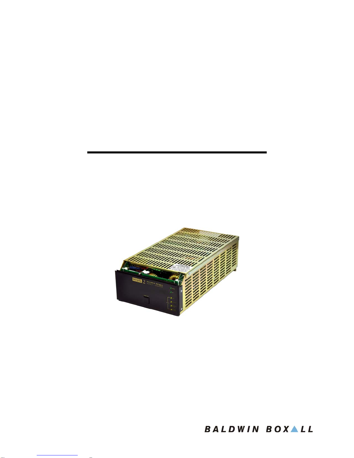
BVSMP / BVSMPLT Power Supply & Charger
Introduction
The BVSMP contains two independent PSU modules and can power either two BV225, two
BV125D or two BV050Q power amplifier modules.
The BVSMPLT contains a single PSU module and can power either one BV225, one
BV125D or one BV050Q power amplifier.
Both the BVSMP and BVSMPLT employ “switch mode” techniques that improve efficiency,
reduce unwanted heat dissipation and weight.
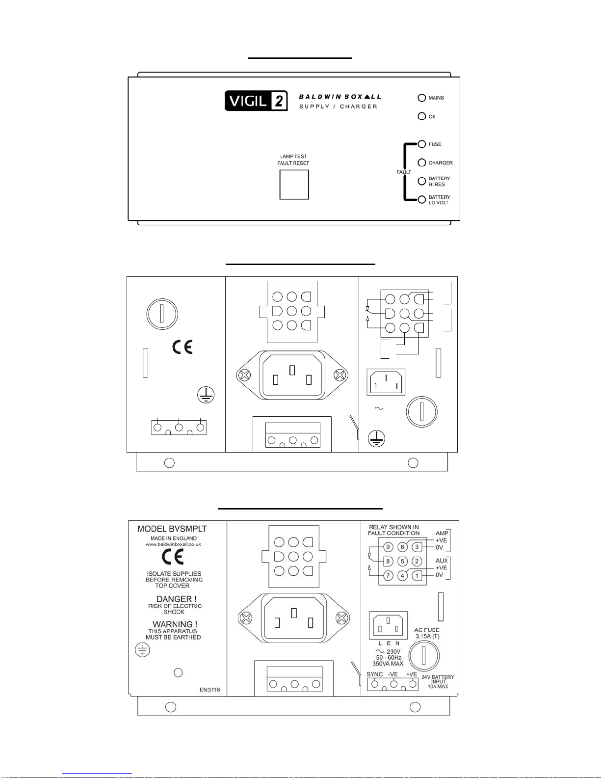
A third fused output is provided to power a mixer or auxiliary circuits. All these outputs
together with a fault volt free changeover contact are provided by a 9 way crimp connector
plug and socket.
Protection and Fuse Monitoring
The power supplies have over Current and over Voltage protection circuits and provide full
monitoring of the Charger and all DC outputs to ensure system reliability.
In the event of mains failure the DC supplies are maintained using an external standby
battery.
The unit has built in deep battery discharge cut off; this prevents total discharge that can
destroy the standby batteries in the event of AC power failure for any long periods.
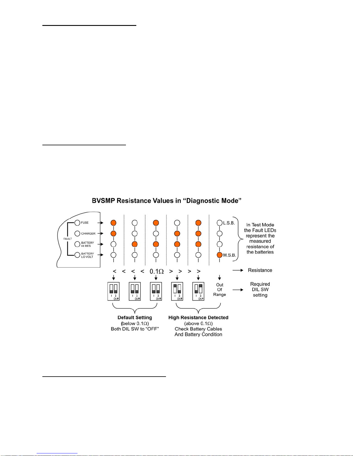
The charger section is totally monitored and has front panel LED fault indicators for the
following states:
AC Supply Healthy,
Fuse failure,
Charger failure,
Battery High Resistance,
Battery Low Voltage.
Should any of the above fault conditions occur an internal relay releases providing a
changeover contact. This fault contact is normally connected to a fault input on a router or
used to indicate a fault at the fire detection panel.
When a fault has been detected the relevant fault LED will illuminate and the OK LED will
extinguish.
If the fault is subsequently cleared, the OK LED will illuminate but the relevant fault LED will
flash to indicate the fault that existed. This is useful when fault finding.
To clear these “previously announced” faults press the Lamp Test button.
The charger incorporated is of the constant voltage type set for the recommended float
charge. Should the battery be below this voltage the BVSMP will charge in a constant current
mode at the rate of 3 amps which progressively reduces once the battery has achieved its
nominal float level. Upto 4 chargers may be paralleled together when used for larger
systems, however they must be synchronised together.
When paralleling units the “SYNC” connection on the 3 way battery connectors must all be
connected together.

-3-
BVSMP/LT Issue 3 ECR 2544
Battery Resistance Monitoring
The Battery Resistance Monitoring function ensures the battery condition is continuously
monitored, and is a more accurate method than simple voltage measurement.
The BVSMP monitoring meets the requirements of BS EN54-4.
Monitoring is controlled by a 2way DIL switch located behind the front panel.
Note: To ensure compatibility with previous versions of BVSMP the Resistance Monitoring
can be disabled (see “Compatibility Mode” instructions below).
The BVSMP has a factory preset default threshold of 0.1Ωfor the overall resistance of the
cables and batteries. If the BVSMP detects a reading above this threshold then a fault will be
announced.
Depending on the cables and batteries in use it may be necessary to adjust this threshold to
ensure correct fault detection.
BVSMP “Diagnostic Mode”
Press and hold the front panel “Lamp Test / Fault Accept” button for 10 seconds.
The unit will then enter a “Diagnostic Mode” and the Front Panel LEDs will display the
Resistance Value the BVSMP has detected.
This is shown in the following figure:
Set the front panel DIL SW to match the detected resistance.
To leave “Diagnostic” mode and return the BVSMP to normal operation press the
“Lamp Test / Fault Accept” for 10 seconds.
Compatibility Mode (Both DIL SW “ON”)
The resistance monitoring function must be disabled if the BVSMP is being retro-fitted to a
system with other non-resistance monitoring BVSMP units.
Set both DIL SW to “ON” to disable resistance monitoring.
In “Compatibility Mode” the battery monitoring detects and displays “Battery Low Voltage”
faults.

-4-
BVSMP/LT Issue 3 ECR 2544
BVSMP / BVSMPLT SPECIFICATIONS
BVSMP BVSMPLT
AC supply input Voltage 200V – 250V 50 – 60Hz 200V – 250V 50 – 60Hz
Maximum power consumption: 700VA 350VA
Maximum inrush current @ 230V: 18A 9A
DC output 1 to amplifier 1: 31V @ 12A 31V @ 12A
DC output 2 to amplifier 2: 31V @ 12A --
DC output 3 auxiliary mixers etc: 31V @ 2A 31V @ 1A
Battery charger output:
Voltage @ 20 °C: 27.1V
Temperature compensation: -66mV/°C
Maximum current: 3A
Battery deep discharge cut off Voltage: 16V
Volt free fault relay output contacts: 100V @ 1A max
Fuse protection:
AC supply (5 x 20mm): 2 x 3.15A(T) 1x 3.15A(T)
Battery (automotive blade): 2 x 20A 1 x 20A
Charger input (self-resettable): 6A 6A
Charger output (self-resettable): 4A 4A
Aux output (self-resettable): 1.1A 1.1A
Front panel indicators:
AC supply AC supply ‘ON’
OK No Fault
Fuse Fuse Fault
Charger
Charger Fault
(Charger Input <29V)
(Charger Output either <21V or >29V)
(Charger Regulator not operating)
Battery High Resistance Battery High Resistance Fault (default >0.1Ω)
Battery Low Voltage Battery Voltage Low fault (<21V)
Lamp test for the above indicators
Terminations:
AC supply input: IEC 6A filtered connector
24V battery input: 3-pin screw terminated connector
DC outputs & fault relay contacts: 9-pin crimp terminated connector

-5-
BVSMP/LT Issue 3 ECR 2544
Front Panel View
BVSMP Rear Panel View
BVSMPLT Rear Panel View
+VE-VE
NE
24V BATTERY INPUT 20A MAX
SYNC
L
AC FUSE
IN FAULT COND.
RELAY SHOWN
MUST BE EARTHED
THIS APPARATUS
WARNING!
EN1722
www.baldwinboxall.co.uk
AC FUSE
3.15A(T)
3.15A(T)
MODEL BVSMP. MADE IN ENGLAND
1
2
3
4
5
6
7
8
9
+VE
0V
0V
+VE
A
MP1
A
MP2
0V
+VE
A
UX
230V
50-60Hz
700VA MAX
AMP2
AMP1
This manual suits for next models
1
Table of contents