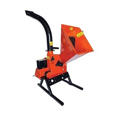
balfor BF150 User manual

12030 Manta (CN) - Via Galimberti, 64 - Tel. 0175 289070 - Fax 0175 289016
www.balfor.it e-mail: [email protected]
C
CH
HI
IP
PP
PI
IN
NG
G
M
MA
AC
CH
HI
IN
NE
E
B
BF
F1
15
50
0
Models:
BF150
TECHNICAL MANUAL OF USE AND MAINTENANCE FOR THE USER
“Contains Declaration of Conformity” (CE)
Read this Manual carefully before using the machine
“Original instructions”

Use and maintenance manual
Chipping machine BF150
1
CE DECLARATION OF CONFORMITY
BALFOR s.r.l. company
REGISTERED OFFICE – PLANT AND ADMINISTRATION:
Via Galimberti, 64 – 12030 MANTA (CN) ITALIA - Tel. 0175 289070
Declares under its own responsibility that the machine:
CHIPPING MACHINE FOR BRANCHES
Place and date: Manta, 1 September 2023

Use and maintenance manual
Chipping machine BF150
2
CHIPPING MACHINES FOR COMPOSTING
CARDAN MODELS
It complies with all relevant provisions of the following European Directive:
Directive 2006/42/CE on machinery and amending directive 95/16/CE.
Having applied the following harmonised standards and technical specifications for the adaptation of
the machine, to the extent that they are relevant:
UNI EN ISO 12100:2010 “Safety of machinery – General design principles – Risk assessment and risk
reduction”.
UNI EN ISO 4254-1:2022 “Farm machinery - Safety - Part 1: General requirements”.
ISO 11684 “Tractors, agricultural and forestry machinery, garden machinery - Safety signs and risk
warning pictograms - General principles”.
Person authorised to compile the technical file:
Technical Department – Gianluca Ballario at company headquarters offices.
The legal representative

Use and maintenance manual
Chipping machine BF150
3
INDEX
1GENERAL INFORMATION............................................................................................................................. 4
1.1 ABOUT THIS MANUAL ............................................................................................................................................5
1.2 MACHINE IDENTIFICATION ....................................................................................................................................5
1.3 INFORMATION ABOUT THE MACHINE...................................................................................................................6
1.3.1 Intended uses....................................................................................................................................................6
1.3.1 Model identification .........................................................................................................................................7
1.4 COMPONENTS AND TECHNICAL DATA ..................................................................................................................8
1.4.1 Cardan models.................................................................................................................................................8
1.4.2 Noise level.......................................................................................................................................................10
1.4.3 Vibration level.................................................................................................................................................10
1.4.4 Dust emission..................................................................................................................................................10
2SAFETY REQUIREMENTS............................................................................................................................ 11
2.1 GENERAL SAFETY AND ACCIDENT PREVENTION RULES.......................................................................................11
2.2 SPECIFIC SAFETY REQUIREMENTS .......................................................................................................................14
2.2.1 Cardan models (C) ..........................................................................................................................................14
2.3 SAFETY SIGNS .......................................................................................................................................................15
2.3.1 On all models ..................................................................................................................................................15
2.3.2 On cardan models only (C) .............................................................................................................................16
3TRANSPORT AND LIFTING ......................................................................................................................... 17
3.1 CHECKING THE LIFTING CAPACITY AND STABILITY OF THE TRACTOR..................................................................18
3.2 ROAD CONDITIONS ..............................................................................................................................................19
4FOLDING OF LOADING AND UNLOADING DUCTS...................................................................................... 20
5CONNECTIONS........................................................................................................................................... 22
5.1 CONNECTION TO THE TRACTOR’S THREE-POINT HITCH .....................................................................................22
5.1.1 Cardan shaft installation ................................................................................................................................23
6USE AND OPERATION ................................................................................................................................ 24
6.1 EXHAUST DUCT ADJUSTMENT .............................................................................................................................26
6.2 EMERGENCY LEVER FOR LOOSENING DRIVE BELTS.............................................................................................28
6.3 OPERATING CYCLE ...............................................................................................................................................30
7MAINTENANCE.......................................................................................................................................... 31
7.1 LUBRICATION AND GREASING .............................................................................................................................32
7.2 KNIFE AND COUNTER-KNIFE SHARPENING..........................................................................................................33
7.3 LID OPENING FOR KNIFE CHANGE .......................................................................................................................35
7.4 DRIVE BELT TENSIONING .....................................................................................................................................36
8STORAGE ................................................................................................................................................... 37
8.1 SCRAPPING...........................................................................................................................................................38
9WARRANTY................................................................................................................................................ 39
10 SPARE PARTS ............................................................................................................................................. 40
January 2023 Edition


Use and maintenance manual
Chipping machine BF150
4
1GENERAL INFORMATION
The models presented in this manual are exclusively designed for shredding and chipping branches,
pruning residues, brushwood, wood products in general in order to obtain chips and a uniform product
suitable for composting.
The use of original spare parts and accessories is recommended. In addition to invalidating the
warranty, non-original parts could be dangerous and reduce the life and performance of the machine.
The BALFOR s.r.l. company has compiled this manual to assist you in the maintenance and use of this
machine, which, despite being an easy-to-use tool, requires you to scrupulously observe what follows in
order to avoid damage to the machine and accidents to the operator.
COPYRIGHT BY BALFOR s.r.l.
All rights reserved regarding this "Instructions for use and maintenance"
manual belong to the Manufacturer. All information (text, drawings,
diagrams, etc.) contained herein is reserved. No part of this manual may
be reproduced or distributed (whether in whole or in part) by any means of
reproduction (photocopies, microfilm or other) without the Manufacturer's
written permission.
The desire to save energy and use renewable sources is behind the decision to invest in highly
sophisticated equipment that allows substantial autonomy.
All of
BALFOR
's production is manufactured using exclusively solar energy.
The company has adopted a powder coating system with advantages from a qualitative and ecological
point of view as it does not create any kind of problem for either the operators or the environment.

Use and maintenance manual
Chipping machine BF150
5
1.1 ABOUT THIS MANUAL
This manual provides all the information for the use and maintenance of the machine. Good operation
and longevity will depend on good maintenance and careful use. It is recommended that you read this
Use and Maintenance Manual carefully, and strictly follow the instructions described before any use,
check and operation to be carried out with and on the machine.
The manual (together with the CE Declaration of Conformity) is to be considered an integral part of the
machine and must always accompany it even in the event of resale.
The topics covered in this manual on the safe use of the chipping machine are those expressly required
by the “Machinery Directive” and the corresponding applicable technical standards (as far as relevant).
The manual was compiled in accordance with the regulations in force at the time of its printing.
SAFETY SYMBOL
This symbol highlights messages that are important for the safety and
security of the operator. When encountered, follow the instructions of the
message to which they refer in order to prevent accidents or injuries.
1.2 MACHINE IDENTIFICATION
On the frame of each machine a plate is attached
bearing the CE mark, the Manufacturer's data, the
model, the serial number, the year of construction and
the mass of the chipping machine.
The CE mark and the CE Declaration of Conformity
certify that the machine is built in accordance with the
“Machinery Directive”.
When requesting spare parts, always refer to the
machine type, serial number and year of construction.

Use and maintenance manual
Chipping machine BF150
6
1.3 INFORMATION ABOUT THE MACHINE
1.3.1 INTENDED USES
The models presented in this manual are exclusively designed for shredding and chipping branches,
pruning residues, brushwood, wood products in general in order to obtain chips and a uniform product
suitable for composting.
They also allow the reduction of the mass of wood-based plants so as to facilitate their disposal and
transport.
Any use other than that specified is considered improper.
The person operating the machine must always be positioned in front, close to the loading mouth.
Operating position
Machines powered by a cardan shaft must remain connected to the tractor at all times during use.
The machine cannot be used indoors.
These machines are usually used during the day. If use at night or in reduced visibility conditions is
required, a proper lighting system must be employed around the machine.
ATTENTION!
THE MACHINE MUST BE OPERATED BY ONE OPERATOR ONLY.

Use and maintenance manual
Chipping machine BF150
7
1.3.1 MODEL IDENTIFICATION
BF
chipping machines work on the ground.
The machine is essentially composed of the lifting frame, the loading hopper, the drum case consisting
of a disc with 2 knives made of high-strength steel, and the rotatable and adjustable deflector for
unloading the chippings. The chipper is activated directly via the tractor's power take-off; by inserting
the branches, thanks to the chute of the hopper, which exploits gravity, and thanks to the rotation of
the knife, the chipping phase begins with the following discharge of the material from the adjustable
deflector.
The
BALFOR s.r.l.
company produces this type of chipping machine in the following version:
Cardan models: BF150 C
BF150 indicates maximum shredding diameter 15 cm.
The information in the following chapters applies to all machine models.
In some sections, specific information will be given depending on the machine model and version you
are using.

Use and maintenance manual
Chipping machine BF150
8
1.4 COMPONENTS AND TECHNICAL DATA
1.4.1 CARDAN MODELS
Ref
Description
Ref
Description
A
Supply duct
H
Cardan shaft coupling
B
Supply duct closure
I
Three-point hitch
C
Exhaust duct
J
Lifting arm hitch
D
Exhaust duct deflector
K
Lever for loosening belts
E
Lifting eye
L
Lever for resetting belt tension
F
Fork insertion housing
M
Opening for inserting reset lever
G
Shredding rotor
A
F
H
C
D
M
L
B
E
I
J
K
G

Use and maintenance manual
Chipping machine BF150
9
Model
BF 150- C
Max. exhaust duct height (mm)
2560
Max. supply duct height (mm)
1200
Max. length (mm)
2000
Length with folded supply duct (mm)
1530
Width with closed exhaust duct (mm)
1000
Mass (kg)
420
Loading duct opening dimensions (mm)
480x740
Maximum diameter of branches to be shredded (mm)
150
Min. and max. tractor power requirement (hp)
45 - 80
ATTENTION!
THE MACHINE WAS DESIGNED TO BE DRIVEN BY A TRACTOR WITH A MAXIMUM
POWER OF 80hp (58 Kw), FOR HIGHER POWER THE MECHANICS MAY BE
DEFORMED OR BROKEN, AND THE DRIVE BELTS MAY SLIP.

Use and maintenance manual
Chipping machine BF150
10
1.4.2 NOISE LEVEL
The values quoted are emission levels and are not necessarily safe working levels.
Although there is a correlation between emission and exposure levels, this cannot be used reliably to
determine whether or not additional precautions are required. Factors influencing the current exposure
level of the workforce include the characteristics of the working environment, other noise sources etc.,
i.e., the number of adjacent machines and other processes. In addition, the allowable exposure level
may vary according to country. However, this information allows the machine user to make a better
danger and risk assessment.
Since the sound pressure level (LPA) can vary significantly depending on the type of environment (more
or less reverberant) in which the machine is installed, the sound power level (LWA) emitted by the
machine is given, which is an absolute figure independent of the environment.
Cardan models
The measured values of LpA e Lwa are as follows:
Sound power during cutting operation LWA dB(A) = 108.5
Sound power, no-load operation LWA dB(A) = 108.0
Uncertainty assured K = 4 dB
Sound pressure LPA dB(A) at operator's workstation during cutting operation = 90.5
Sound pressure LPA dB(A) at operator's workstation, no-load operation = 89.5
Regular maintenance of the machine and blades according to the instructions provided in the Use and
Maintenance Manual will keep noise emission levels low over time.
1.4.3 VIBRATION LEVEL
The machine is designed and constructed to minimise operation-induced vibrations and the operator is
not affected by these because he is not standing on the machine.
The level of vibrations transmitted by the machine to the worker (HAV hand-arm system) during the
work phase (during cutting, the operator presses the piston release levers with both hands) is less than
2.5 m/s2.
1.4.4 DUST EMISSION
Wood cutting operations are subject to the emission of wood shavings and dust. In particular, dust can
be dangerous if inhaled, and the risk can be increased by certain factors such as the type of wood
being processed, particularly dry weather and the presence of wind which increase the volatility of dust,
and in closed environments the presence of air currents.
Depending on how the machine is used and the type of wood being processed, the user company is
obliged to adopt the most appropriate protective measures in accordance with its own risk assessment,
such as the use of respiratory protective devices, the presence of localised or centralised suction
systems and regular cleaning of the workstation.

Use and maintenance manual
Chipping machine BF150
11
2SAFETY REQUIREMENTS
THE FOLLOWING SAFETY INSTRUCTIONS ARE INTENDED TO SAFEGUARD YOUR SAFETY:
YOU SHOULD THEREFORE READ THEM CAREFULLY, MEMORISE THEM AND APPLY THEM AT
ALL TIMES
SAFETY SYMBOL
This symbol highlights messages that are important for the safety and
security of the operator. When encountered, follow the instructions of the
message to which they refer in order to prevent accidents or injuries.
Operate the machine, carry out periodic inspections and maintenance work in accordance with the Use
and Maintenance Manual. Proper maintenance is a guarantee of excellent cutting performance.
The chipping machine was built solely for shredding branches, pruning residues, brushwood, wood
products in general in order to obtain chips and a uniform product suitable for composting.
The warnings in this manual only concern permitted and reasonably foreseeable uses. The indications
below should be supplemented by the common sense and experience of the operator, which are
indispensable measures for accident prevention.
The machine may only be used by authorised, informed and trained personnel who are familiar with its
operation and dangers.
Any changes to the machine not previously authorised by the Manufacturer (in writing) exclude its
liability.
2.1 GENERAL SAFETY AND ACCIDENT PREVENTION RULES
Basic rule: Carry out an inspection of the machine before each start-up.
It is forbidden to use the machine for shredding materials other than those indicated in this manual.
It is forbidden to use the machine in closed places as the exhaust gases of the tractor to which the
machine is to be connected are harmful.
Observe all general safety and accident prevention regulations in addition to the warnings
contained in this manual. Before starting to use the machine, you must be familiar with its features,
all devices, controls and functions.
Before starting work, ensure that the transmission is latched in the working position, that the
tension of the belts is correct and that the hopper is open and secured with the safety pins.
The safety signs attached to the machine provide a number of very important indications: observing
them serves your safety. Carefully read the safety decals attached to the machine and follow the
instructions. In the event of deterioration or poor legibility of the safety pictograms, clean or replace
them by placing them in the original position.

Use and maintenance manual
Chipping machine BF150
12
The machine complies with the general principles of electrical equipment safety and therefore any
change in the structure or components of this system would alter the characteristics of the system,
which would no longer meet the necessary safety requirements.
Only operate the machine on a compact, level and obstacle-free ground, ensuring that it is
stationary and stable.
ATTENTION!
It is forbidden to stand within range of the machine during its operation.
ATTENTION!
Anyone approaching the machine is in the danger zone and therefore becomes an
“
EXPOSED PERSON
”. The operator must prevent anyone from entering the danger
zone and operate the machine himself with the utmost caution. Should anyone
approach, stop the machine immediately.
The Use and Maintenance Manual must always be at hand so that it can be consulted to check the
operating cycle. If it is lost or damaged, a replacement copy must be requested from BALFOR s.r.l.
The machine must only be operated by authorised, instructed and appropriately trained personnel.
ATTENTION!
The machine is designed to be used by one operator only who must always be
positioned in front of the chipping machine control levers.
Do not wear clothing that can cause entanglement (sleeves without a closed cuff, belts, necklaces).
ATTENTION! - WARNING!
The operator, while using the chipping machine, must wear safety shoes, work gloves, safety
goggles, noise-reducing headphones and an appropriate dust mask to protect himself from
falling objects, projections of material, noise emissions and the release of dust.
The machine must not be left unattended when it is running.
Check that the machine has not been damaged during transport and inform BALFOR s.r.l.
immediately if this is the case.
Keep the machine clean of foreign materials (debris, tools, various objects) that could damage its
operation or cause harm to the operator.
Pay attention to the particular characteristics of the branches to be chipped.

Use and maintenance manual
Chipping machine BF150
13
ATTENTION!
For proper operation of the chipping machine and to avoid accidents,
logs/branches must not be 'pushed' towards the rotor. If dragging does not
occur, sharpen/change the knives.
Use only original BALFOR s.r.l. spare parts.
ATTENTION!
The
BALFOR s.r.l.
company
is not liable for any damage caused by unreasonably
foreseeable or improper use of the machine.
The
BALFOR s.r.l.
company is relieved of any liability in the event of:
-improper use of the machine, use by personnel not informed on the safe use of the machine;
-serious shortcomings in the planned maintenance
-unauthorised modifications or interventions;
-use of non-original or model-specific spare parts;
-total or partial non-compliance with the instructions;
-non-compliance with common safety rules in the working environment;
-exceptional events.

Use and maintenance manual
Chipping machine BF150
14
2.2 SPECIFIC SAFETY REQUIREMENTS
2.2.1 CARDAN MODELS (C)
ATTENTION!
Any maintenance, adjustment and cleaning work must be carried out with the
machine on the ground, the tractor engine switched off, the handbrake on, the
ignition key switched off and removed from the ignition switch.
ATTENTION!
Do not, under any circumstances, stand between the tractor and the machine with
the engine running and the power take-off engaged
.
Never use the machine in closed or poorly ventilated rooms (even if doors and windows are open)
as the tractor's exhaust gases are poisonous.
Cardan models can only be used if they are connected to the tractor's three-point hitch.
Disconnect the machine from the tractor only on compact, level ground, making sure it is stationary
and stable.
DANGER!
Check that the drive shaft guards are intact and in good condition.
If the cardan shaft guards break or deteriorate, they must be replaced immediately.
When the machine is not attached to the power unit, the cardan shaft must be placed on the
appropriate support.

Use and maintenance manual
Chipping machine BF150
15
2.3 SAFETY SIGNS
Make sure that the safety pictograms are legible. Clean them using a cloth, soap
and water. Replace damaged labels by placing them in the original position.
The safety signs attached to the machine provide a number of very important indications: observing
them serves your safety.
2.3.1 ON ALL MODELS
1. ATTENTION! – DANGER!
The machine must be used by one operator only.
2. ATTENTION!
Use the required personal protective equipment (
earmuffs, work gloves, safety
shoes, safety goggles and dust masks
).
3. WARNING!
When lifting, only hook the machine at the point indicated.
4. DANGER!
of crushing and shearing of hands.
Be careful when handling ducts
.
5. ATTENTION!
Possible throwing of material,
do not stand by or approach the machine
. Maintain
a minimum safety distance of 30 m from the machine.
6. ATTENTION!
Moving parts,
ensure that the drum is completely stationary before lifting the
loading duct.

Use and maintenance manual
Chipping machine BF150
16
2.3.2 ON CARDAN MODELS ONLY (C)
7. ATTENTION!
Read the Use and Maintenance Manual.
Stop the tractor engine and remove the key from the dashboard before carrying
out any work on the machine.
8.
ATTENTION!
DANGER
of entanglement and dragging.
Do not put your hands near the drive shaft while it is in motion.
9. ATTENTION!
Check the direction of rotation and speed (540 rpm) of the tractor's PTO before
inserting the cardan shaft.

Use and maintenance manual
Chipping machine BF150
17
3TRANSPORT AND LIFTING
BF150 C models can be hooked up and transported using the tractor's three-point hitch.
For connection to the tractor see next section.
The chipping machine can be moved by crane, using approved hooks and ropes suitable for the weight
of the machine itself.
The machine can be lifted with the supply duct in either the open (working) or folded position.
ATTENTION!
Pay the utmost attention and caution when loading and unloading the machine.
These operations must be carried out by qualified personnel (slingers, forklift
drivers, etc.).
All machines can be lifted and transported by crane or hoist, using
hooks and ropes (approved and suitable for the weight of the
machine) which must be hooked to the appropriate ring indicated
by the pictogram on the machine. Use a secure hook (i.e.,
carabiner hook) for lifting.
ATTENTION! – DANGER!
It is forbidden to pass through or stand under the lifted load during lifting.
It is forbidden to leave the lifting device with the lifted load.
If the machine is to be loaded onto another means of transport (e.g., a trailer), it must be securely tied
and fastened to the platform by means of lashing ropes.

Use and maintenance manual
Chipping machine BF150
18
3.1 CHECKING THE LIFTING CAPACITY AND STABILITY OF THE TRACTOR
For cardan and hydraulic socket models only (C)
ATTENTION! – DANGER!
It is mandatory to check the lifting capacity and stability of the tractor (prior to
coupling with the machine) to avoid overturning and/or loss of grip of the
steering wheels.
Check the lifting capacity and stability of the tractor using the following formula and if necessary, apply
ballast at the front.
M X s < 0,2 T X i + Z (d + i)
M < 0,3 T
i
=
tractor wheel base
d
=
distance of front axle from ballast
s
=
overhang from the rear axle of the
operating machine
T
=
tractor mass + 75 kg (operator)
Z
=
ballast mass
M
=
machine mass

Use and maintenance manual
Chipping machine BF150
19
3.2 ROAD CONDITIONS
Road behaviour, steering and braking ability are influenced by the assembled tools.
Always drive at a moderate speed, especially on uneven surfaces and steep slopes, to avoid
unbalancing.
The front axle of the tractor is lightened in relation to the weight attached at the time of coupling to the
chipping machine: the front axle load must be at least 20% of the tractor's unladen weight.
ATTENTION!
The traffic regulations in force in the country of use must be strictly adhered to.
If the trailed machine conceals the lighting equipment of the tractor to which it is
attached by its shape, it must be equipped with a rear light bar.
When transferring by road, it is necessary to place the loading duct in the folded position.
ATTENTION!
During transport with the machine raised, always ensure that the lift control lever
is locked to prevent accidental lowering of the machine.
In addition to complying with the regulations, it should be remembered that when driving on public
roads, great attention must be paid, in addition to any special requirements noted in the tractor's
registration certificate, to the choice of an appropriate transfer speed, especially with carry-type
equipment with strong rear overhangs or when the road is crowded, winding or sloping.
ATTENTION!
When driving on the road, the yellow or orange flashing light device fitted on the
tractor must always remain in operation even during the daytime.
When travelling on the road, do not exceed the speed prescribed by the Highway Code in force in the
country in which you are using the machine, and in any case do not exceed 40 km/h as a maximum
limit.
Table of contents