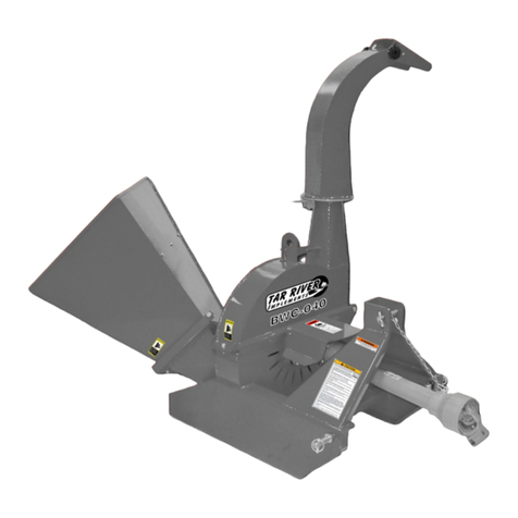
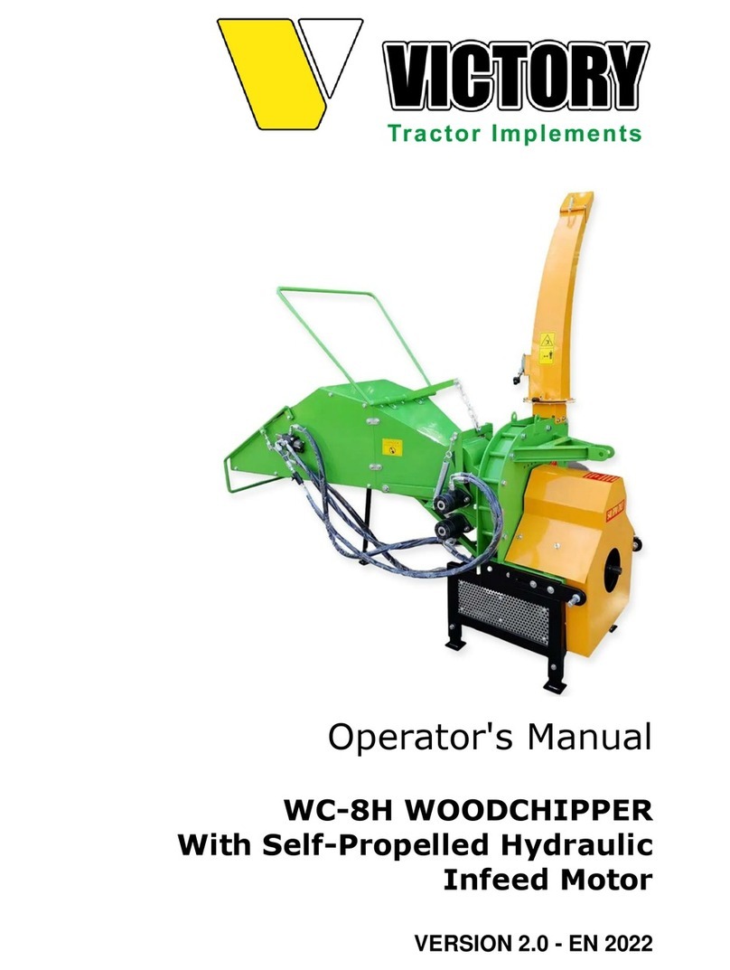
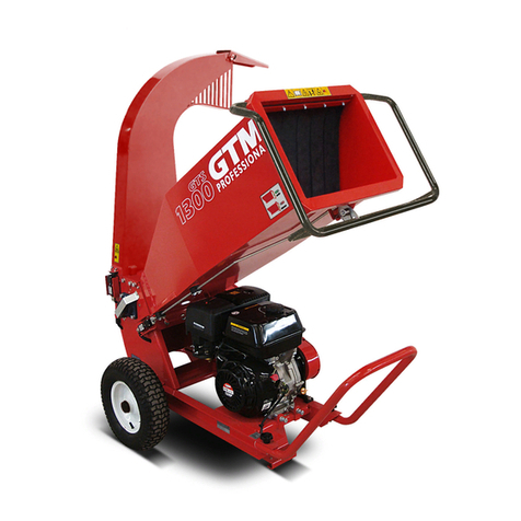
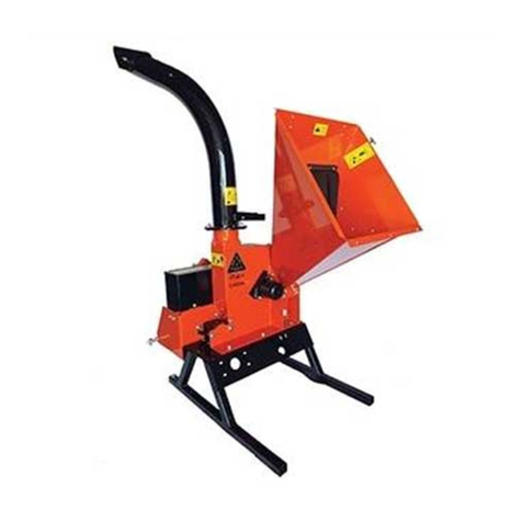
Tar River BWC-040 User manual

BWC-040
BWC-060
BWC-040EC
Wood Chipper
Operator’s Manual
Parts Breakdown
Publicaon #: March 2018

TABLE OF CONTENTS
2
Introduction 3
Safety 3
Safety Signal Words 4
General Safety Guidelines 4
Safety Decal Care 5
Before Operation 5
After Operation 6
Highway and Transport Operations 7
Operation 9
Shortening PTO 9
Start Up 10
Starting up Machine 10
Stopping the Machine 10
Adjustments 10
Feeding 11
Plugging 11
Sharpening Blades 11
Blade / Anvil Clearance 12
Twig Breaker 12
Troubleshooting 13
BWC-040 14-15
BWC-060 16-17
PTO Shaft 18
Warranty 19

INTRODUCTION
Thank you for purchasing your Belco Resources Equipment BWC Wood Chipper. Your wood
chipper is design to be used on Cat. 1 540 rpm tractors. It is important to properly maintain in
keep in place all safety guards and shields that came with your chipper.
SAFETY
Read and understand this manual and all safety signs before operating and maintaining. Review the safe-
ty instructions and precautions annually.
TAKE NOTE! THIS SAFETY ALERT SYMBOL FOUND THROUGHOUT THIS MANUAL IS
USED TO CALL YOUR ATTENTION TO INSTRUCTIONS INVOLVING YOUR PERSONAL
SAFETY AND THE SAFETY OF OTHERS. FAILURE TO FOLLOW THESE INSTRUCTIONS
CAN RESULT IN INJURY OR DEATH.
THIS SYMBOL MEANS
ATTENTION!
BECOME ALERT!
YOUR SAFETY IS INVOLVED!
3

SAFETY SIGNAL WORDS
Safety of the operator is one of the main concerns in designing and developing a new piece of equipment. Designers and manu-
facturers build in as many safety features as possible. However, every year many accidents occur which could have been avoided
by a few seconds of thought and a more careful approach to handling equipment. You, the operator, can avoid many accidents by
observing the following precautions in this section. To avoid personal injury, study the following precautions and insist those
working with you, or for you, follow them.
Replace any CAUTION, WARNING, DANGER or instruction safety decal that is not readable or is missing. Location of such
decals is indicated in this booklet.
Do not attempt to operate this equipment under the influence of drugs or alcohol.
Review the safety instructions with all users annually.
This equipment is dangerous to children and persons unfamiliar with its operation. The operator should be a responsible adult
familiar with farm machinery and trained in this equipment’s operations. Do not allow persons to operate or assemble this unit
until they have read this manual and have developed a thorough understanding of the safety precautions and of how it
works.
To prevent injury or death, use a tractor equipped with a Roll Over Protective System (ROPS). Do not paint over, remove or de-
face any safety signs or warning decals on your equipment. Observe all safety signs and practice the instructions on them.
Never exceed the limits of a piece of machinery. If its ability to do a job, or to do so safely, is in question - DON’T TRY IT.
Note the use of the signal words DANGER, WARNING and CAUTION with the safety messages. The appropriate
signal word for each has been selected using the following guidelines:
DANGER: Indicates an imminently hazardous situation that, if not avoided, will result in death or serious injury.
This signal word is to be limited to the most extreme situations typically for machine components which, for func-
tional purposes, cannot be guarded.
WARNING: Indicates a potentially hazardous situation that, if not avoided, could result in death or serious injury,
and includes hazards that are exposed when guards are removed. It may also be used to alert against unsafe practic-
es.
GENERAL SAFETY GUIDELINES
4

• Keep safety signs clean and legible at all times.
• Replace safety signs that are missing or have become illegible.
• Replaced parts that displayed a safety sign should also display the current sign.
• Safety signs are available from your Distributor or Dealer Parts Department or the factory.
How to Install Safety Signs:
• Be sure that the installation area is clean and dry.
• Decide on the exact position before you remove the backing paper.
• Remove the smallest portion of the split backing paper.
• Align the decal over the specified area and carefully press the small portion with the exposed sticky backing in place.
• Slowly peel back the remaining paper and carefully smooth the remaining portion of the decal in place.
• Small air pockets can be pierced with a pin and smoothed out using the piece of decal backing paper.
• Carefully study and understand this manual.
• Do not wear loose-fitting clothing, which may catch in moving parts.
• Always wear protective clothing and substantial shoes.
• Assure that all tires are inflated evenly.
• Give the unit a visual inspection for any loose bolts, worn parts or cracked welds, and make necessary repairs. Follow the
maintenance safety instructions included in this manual.
• Be sure that there are no tools lying on or in the equipment.
• Do not use the unit until you are sure that the area is clear, especially children and animals.
SAFETY DECAL CARE
BEFORE OPERATION
5

• Don’t hurry the learning process or take the unit for granted. Ease into it and become familiar with your new equipment.
• Practice operation of your equipment and its attachments. Completely familiarize yourself and other operators with its opera-
tion before using.
• Use a tractor equipped with a Roll Over Protective System (ROPS) and fasten your seat belt prior to starting the engine.
• The manufacturer does not recommend usage of tractor with ROPS removed.
• Move tractor wheels to the widest recommended settings to increase stability.
• Securely attach to towing unit. Use a high strength, appropriately sized hitch pin with a mechanical retainer and attach safety
chain.
• Do not allow anyone to stand between the tongue or hitch and the towing vehicle when backing up to the equipment.
• Children should not be allowed on the product.
• Clear the area of small children and bystanders before moving the feeder.
• If using a towing unit, securely attach feeder by using a hardened 3/4” pin, a metal retainer, and safety chains if required. Shift
towing unit to a lower gear before going down steep downgrades, thus using the engine as a retarding force. Keep towing ve-
hicle in gear at all times. Slow down for corners and rough terrain.
• Make sure you are in compliance with all local and state regulations regarding transporting equipment on public roads and
highways. Lights and slow moving signs must be clean and visible by overtaking or oncoming traffic when feeder is trans-
ported.
• Beware of bystanders, particularly children! Always look around to make sure that it is safe to start the engine of the towing
vehicle or move the unit. This is particularly important with higher noise levels and quiet cabs, as you may not hear people
shouting.
• NO PASSENGERS ALLOWED - Do not carry passengers anywhere on, or in, the tractor or equipment, except as required
for operation.
• Keep hands and clothing clear of moving parts.
• Do not clean, lubricate or adjust your equipment while it is moving.
• When halting operation, even periodically, set the tractor or towing vehicle brakes, disengage the PTO, shut off the engine and
remove the ignition key.
• \Be especially observant of the operating area and terrain - watch for holes, rocks or other hidden hazards. Always inspect the
area prior to operation.
DURING OPERATION
6

• DO NOT operate near the edge of drop-offs or banks.
• DO NOT operate on steep slopes as overturn may result.
• Operate up and down (not across) intermediate slopes. Avoid sudden starts and stops.
• Adopt safe driving practices:
• Keep the brake pedals latched together at all times. NEVER USE INDEPENDENT BRAKING WITH MACHINE IN
TOW AS LOSS OF CONTROL AND/OR UPSET OF UNIT CAN RESULT.
• Always drive at a safe speed relative to local conditions and ensure that your speed is low enough for an emergency stop to be
safe and secure. Keep speed to a minimum.
• Reduce speed prior to turns to avoid the risk of overturning.
• Avoid sudden uphill turns on steep slopes.
• Always keep the tractor or towing vehicle in gear to provide engine braking when going downhill. Do not coast.
• Do not drink and drive!
• Comply with state and local laws governing highway safety and movement of farm machinery on public roads.
• Use approved accessory lighting flags and necessary warning devices to protect operators of other vehicles on the highway
during daylight and nighttime transport. Various safety lights and devices are available from your dealer.
• The use of flashing amber lights is acceptable in most localities. However, some localities prohibit their use. Local laws
should be checked for all highway lighting and marking requirements.
• When driving the tractor and equipment on the road or highway under 40 kph (20 mph) at night or during the day, use flash-
ing amber warning lights and a slow moving vehicle (SMV) identification emblem.
• Plan your route to avoid heavy traffic.
• Be a safe and courteous driver. Always yield to oncoming traffic in all situations, including narrow bridges, intersections, etc.
• Be observant of bridge loading ratings. Do not cross bridges rated lower than the gross weight as which you are operating.
HIGHWAY AND TRANSPORT OPERATIONS
7

• Watch for obstructions overhead and to the side while transporting.
• Always operate equipment in a position to provide maximum visibility at all times. Make allowances for
increased length and weight of the equipment when making turns, stopping the unit, etc.
• Pick the levelest possible route when transporting across fields. Avoid the edges of ditches or gullies and
steep hillsides.
• Be extra careful when working on inclines.
• Maneuver the tractor or towing vehicle at safe speeds.
• Avoid overhead wires or other obstacles. Contact with overhead lines could cause serious injury or death.
• Avoid loose fill, rocks and holes; they can be dangerous for equipment operation or movement.
• Allow for unit length when making turns.
• Operate the towing vehicle from the operator’s seat only.
• Never stand alongside of unit with engine running or attempt to start engine and/or operate machine while
standing alongside of unit.
• Never leave running equipment attachments unattended.
• As a precaution, always recheck the hardware on equipment following every 100 hours of operation. Cor-
rect all problems. Follow the maintenance safety procedures.
8

Operation
It is important that each operator of the Tar River Wood Chipper read and understand the operational pro-
cedures and all related safety precautions outlined in this section. The following preoperation checklist is
provided for the operator. It is important for both the personal safety and maintaining good mechanical
condition that this checklist is followed.
Caution: Always wear personal protective equipment (PPE) whenever operating the machine. This includes but
is not limited to protective shoes with slip resistant soles, protective goggles or face shield, heavy gloves, hearing pro-
tection and protective clothing.
Do not place metal, bottles, cans, rocks, glass or other solid material into the wood chipper. If something like this gets
into the machine, stop the machine immediately for a detailed inspection. Stop engine, remove ignition key and place in
your pocket and wait for all moving parts to stop before inspecting or unplugging. Inspect machine for damaged or
loosened parts before resuming work.
Prior to operating the Wood Chipper:
1. Lubricate the machine per the schedule out-line in the Maintenance Section.
2. Check the rotor, blades and twig-breaker. Remove any twine, wire or other material that has become entangled.
3. Check the condition and clearance of the twig- breaker, rotor and stationary blades. Adjust or replace as required.
4. Check that all bearings turn freely. Replace any that are rough or seized.
5. Make sure that all guards and shields are in place, secured and functioning as designed.
6. Check the condition of the curtain in the feed hopper. It must be in good condition to prevent chips from flying out.
Shortening a PTO Driveline
Depending on our tractor, it may be necessary to cut the PTO drive line that is
supplied with the machine. To accommodate the variety of 3 point hitch
geometry available, the drive line may be too long or too short for the trac-
tor. It is very important that the drive line be free to telescope but not to
bottom out when going through its working range. If the drive line bot-
toms out, the bearings on both the machine and tractor PTO shaft will be
overloaded and fail in a short time.
1. With the implement attached to the tractor’s three point hitch, and the
PTO driveline not installed, separate the PTO driveline. Attach the im-
plement end to the implement and the other end to the tractor PTO input
shaft.
2. Raise the implement by using the tractor’s hydraulic 3-point hitch to it’s
maximum lift height.
3. Hold the half shafts next to each other and mark them so each end is approximately ½” from hitting the end of the telescopic
profiles.
4. Shorten the inner and out guard tubes equally.
5. Shorten the inner and outer profiles by the same length as the guard tubes. Using a rattail file, round off all sharp edges and
burrs. Grease the telescopic profile generously before reassembling.
9


Do not shorten too much, the proper overlap is a minimum of 1/3 the length of each profile.
Start up
Although there are no operational restrictions on the Wood Chipper when used for the first time, it is recommended that the
following mechanical items be checked:
Before start up and after operating for 1 hour and every 5 Hours of operation
• Torque all fasteners and hardware.
• Check condition of rotor bearings.
• Check the condition and clearance of the twig-breaker, rotor and stationary blades. Adjust or replace as required.
• Check for entangled material. Remove all entangled material before resuming work.
• Lubricate all grease fittings.
Starting the Machine
• Start the tractor engine.
• Move the throttle to its low idle position.
• With the engine at low idle, slowly engage the PTO control.
• Slowly increase the engine speed until the PTO is at rated speed.
• With the manual feeding model, start feeding material into the hopper.
Stopping the Machine
• Stop feeding material into the hopper.
• Place the hydraulic feed control in off neutral.
• Slow engine RPM.
• Place hydraulic lever in its OFF position.
• Disengage PTO.
• Stop engine, remove ignition key and place in your pocket and wait for all moving parts to stop.
Adjustments
Deflector Position
Press down on the discharge pivot clamp to release the positioning pin. Swivel the chute to desired position. Adjust the
Discharge Angle adjuster at the top of the chute.
Chip size
The anvil is mounted on the base with slotted holes. These holes allow the anvil to be moved in order to adjust the size
of the chips you require
10

Feeding
The BWC may be available in either gravity or hydraulically feed.
Danger: If gravity feed be careful not to reach into the feed hopper further than the curtain. To reach
further, use a stick or branch to push any material into the disc that does not go in on its own.
To begin operations, slowly slide the material to be chipped into the hopper. Allow it to feed on its own without excret-
ing much pressure.
Plugging
If plugging occurs, following these procedures:
• Stop the engine, remove the ignition key and place it in your pocket and wait for all moving parts to stop before unplugging.
• Pull the material out of the feed hopper. Be sure all the material is out and nothing is jammed or wedged between the input
opening and the rotor.
• Pull the material out of the discharge hood. Use a stick to poke loose any material jammed into the discharge hood. Do
not allow anything to remain in this area.
•
If severe plugging occurs:
Danger: Ensure the engine is off and you have pocked the key to prevent unintentional startup.
• Loosen the feed hopper anchor nuts and raise the feed hopper. Remove material from inside the rotor compartment.
• Clean out the discharge area/rotor.
• Open the rotor cover and clean out the housing. Be sure to turn the rotor by hand to be sure there is nothing jammed be-
tween the rotor and stationary blades.
• Close, install and fold down all components opened to unplug. Tighten fasteners to their specified torque.
• Check that everyone is clear of machine before restarting engine.
• Start the engine, engage the PTO and resume working.
Sharpening Blades:
The rotor blades and anvil need to be sharp for the chipper to perform as expected. It is recommended that the rotor blades
be removed from the rotor when sharpening. Always sharpen the blades at a 45° angle to provide the best cutting effect as
it meets the anvil. Be sure to tighten the blade mounting bolts to their specified torque when re-installing the blades to the
rotor.
The stationary blade is designed with 4 sharp corners that can be utilized. When the corner facing the rotor blade rounds
over, remove the blade and re-install with a different corner facing the rotor blade. Use the anvil to set the clearance to the
rotor blade when re-installing. Be sure to tighten mounting bolts to their specified torque.
The drive system is designed to function well without failing the shear pin. If it does fail, generally it is being fed too fast
or something very hard has been jammed into the rotor or between the blades. Always unplug the sys- tem and determine
the cause of the problem and correct it before resuming work
11

Anvil/Blade Clearance:
It is recommended that the clearance between the rotor and anvil be set and maintained at 1/32 to 1/16 inch to obtain the best
performance. Use the stationary blade mounting bolts to set the clearance as required.
Twig Breaker:
Caution: Clear the area of bystanders, especially small children.
Stop the engine, remove the ignition key and place it in your pocket and wait for all moving parts to stop before unplugging.
Pull the material out of the feed hopper. Be sure all the material is out and nothing is jammed or wedged between the input
opening and the rotor.
Pull the material out of the discharge hood. Use a stick to poke loose any material jammed into the discharge hood. Do not
allow anything to remain in this area.
12

13
PROBLEM
Rotor not turning.
CAUSE
Obstructed discharge.
SOLUTION
Shut down and clear debris.
Rotor plugged.
Clear rotor.
Broken shear pin.
Replace shear pin.
Slow feeding.
Knives are dull.
Sharpen knives.
Blade angle wrong,
Re-sharpen knives to
improper angle. specified angle.
Discharge hood clogged.
Clear discharge hood.
Chipper requires excessive
power or stalls.
Obstructed discharge.
Rotor plugged.
Clear discharge hood.
Clear rotor.
Green material will not
Allow material to dry or
discharge. alternately feed in dry
material.
Dull knives. Sharpen knives.
High power required
Plugged rotor.
Clear rotor.
Dull knives.
Sharpen knives.
Vibration while running.
Yokes
Drive line vibration.
Check drive line phasing.
must be aligned.
Check rotor to see if it wobbles.
Check to see if rotor is
assembled correctly.
Drive belts slipping or smoking.
Loose or worn belts.
Adjust or replace belts.
Plugged rotor.
Clear rotor.
Troubleshooting

14
Belco Resources Equipment
BWC-040

15
Belco Resources Equipment
BWC-040
Posion Part # Descripon Qty
1BX4-0601 Deector 1
2BM0812516 Bolt - 8x1.25x16 4
3NM80000 Nut 8mm 2
4BX4-9313 Knob - Deector 2
5BX4-0600 Discharge Chute 1
6BM610020 Bolt - 6x1.00x10 10
7BX4-0605 Spacer Ring 2
8BX4-0603 Ring - Fastner Rear 1
9BX4-0501 Disc Housing - Upper disc 1
10 BM1212535 Bolt - 12x1.75x35 7
11 BX4-0207 Latch 1
12 BX4-0801 Top Link Pin 1
13 BX4-0402 Bracket - Input sha 1
14 BX4-0401 Shield - PTO 1
15 147130 PTO Sha Complete 1
16 BM810016 Bolt - 8x1.00x16 16
17 BX4-0201 Blade 4
18 BX4-0102 Disc 1
19 HNM22150 Nut—Hex 22mm 2
20 LW22000 Lock Washer 22mm 2
22 BX4-0701 Hitch Pin - Cat 1 2
23 BX4-0300 Frame 1
25 BUCF208 Bearing UCF208 2
26 BM1420045 Bolt - 14x2.00x45 8
27 BX4-0101 Chute 1
28 BX4-0308 Flap 2
29 BX4-9004 Support - Flap 1
30 BM812530 Bolt - 8x1.25x30 3
31 BX4-9003 Anvil 1
32 BM810016 Bolt - 8x1.00x16 3
33 RC350000 R-Clip 3.5mm 1
34 BX4-0604 Ring - Fastner Latch 1
35 BX4-9007 Latch 1

16
Belco Resources Equipment
BWC-060

17
Belco Resources Equipment
BWC-060
Posion Part # Descripon Qty
1BM610020 Bolt - 6x1.00x20 4
2BX6-0607 Support - Flap 1
3BX6-0903 Flap 2
4BX6-0101 Chute 1
5BM1217535 Bolt - 12x1.75x35 7
6BX6-0901 Anvil 1
7BM1215025 Bolt - 12x1.50x25 3
8BM1420045 Bolt - 14x2.00x45 8
10 BUCF210 Bearing - UCF 210 2
11 BX6-0301 Disc Housing—Upper Disc 1
12 RC350000 R Clip 3.5 1
13 BM610030 Bolt - 6x1.00x30 8
14 BX6-0203 Ring—Fastner Rear 2
15 BX6-0204 Spacer Ring 2
16 BX6-0602 Latch 1
17 BX6-0902 Discharge Chute 1
18 BX6-0202 Chain 1
19 BX6-0201 Spring 1
20 BX6-0905 Deector 1
21 NM10002 Cap Nut 10mm 2
22 BX6-0103 Twig Breaker 1
23 BX4-0801 Top Link Pin 1
24 BX6-0401 Blade 4
25 BX6-0904 Disc 1
26 BX6-R0101 Shield—PTO 1
27 BM1215025 Bolt - 12x1.50x25 16
28 BM1015020 Bolt - 10x1.50x20 2
29 BX6-0102 Shield - PTO 1
30 147130 PTO Complete 1
31 HNM22150 Nut - Hex 22mm 2
32 LW22000 Lock Washer - 22mm 2
33 BX4-0701 Hitch Pin - Cat 1 2
35 BX6-0511 Frame
36 FW10000 Flat Washer - 10mm 2

16
Belco Resources Equipment
BWC-040EC

17
Belco Resources Equipment
BWC-040EC
Item # Part # Descripon Qty
1BX52G-03-01 Deector Latch 1
2LNM08000 locking nut M8 6
3BX52G-01- 1
4BX52G-01-+1
5BX4-0007 Latch 1
6BM0812530 Bolt 8 x 1.25 x 30 1
7GB/T 70.2-2000 round head screw M8×20 2
82
9BM061020 Bolt 6 x 1.0 x 20 4
11 BX52G-04-04 Plasc Curtain 1
12 BX52G-04-03 Support - Plasc Curtain 1
13 LNM06000 Lock Nut 6mm 4
14 Φ10-16×30 lock pin Φ10-16×30 1
15 NM040000 Nut M4 4
16 FW04000 at washer Φ4 4
17 LW04000 Lock Washer 4M 4
18 GB/T 819.1-2000 Cross recessed pan head screws M4x14 4
19 BX52G-01 Chute 1
20 BM142040 Bolt 14 x 2.0 x 40 2
21 LNM14000 Lock Nut 14MM 2
22 LNM10000 Lock Nut 10MM 21
23 GB/T 70.3-2000 hexagon socket countersunk head cap screws M10x30 16
24 BX52G-07-01- Disc 1
25 BX52G-07-02 Blade 4
26 BUCF208 Bearing UCF208 2
27 BX52G-05-02-01.11 Anvil 1
28 FW08000 Flat washer 8M 3
29 LW08000 Lock washer Φ8 3
30 BM0812530 Bolt 8 x 1.25 x 30 3
31 BX52G-04-01 Support - Chute 1
32 Bearing Cover 1
33 BM101525 BM 10 x 1.25 x 25 5
34 BX52G-05-01 Frame 1
35 BX52G-05-02-01- Branch Breaker 1
36 BX52G-05-01-15 Stand 2
37 BM142035 Bolt 14 x 2.0 x 35 8
38 BX4-0701 Lower Hitch Pin 2
39 SB100756 Lynch Pin 3
40 BX52G-05-01-13 Cat 2 lower bushing, Φ22xΦ28-45 2

16
Belco Resources Equipment
BWC-040EC
This manual suits for next models
2
Table of contents
Other Tar River Chipper manuals
Popular Chipper manuals by other brands

Nakayama
Nakayama GS8500 owner's manual

WoodMaxx
WoodMaxx WM Series manual

Caravaggi
Caravaggi Bio 190 Use and maintenance instruction manual

Gude
Gude GH 651 B Translation of the original instructions

REMET CNC
REMET CNC RS80 TECHNICAL AND MOTION DOCUMENTATION, OPERATING INSTRUCTIONS, GUARANTEE CARD, EXCHANGE PARTS CATALOG

Timberwolf
Timberwolf TW 230VTR instruction manual