Ballenger Motorsports AFR500CAN User guide

Ballenger Motorsports AFR500CAN Manual Rev 1.2
- 1 -
Ballenger Motorsports, Inc.
8052 Elm Drive, Ste G
Mechanicsville, VA 23111
Phone: (804) 915-7201
Fax: (804) 433-3825
www.bmotorsports.com
AFR500CAN Setup Manual
(Addendum to AFR500V2 Tuning Manual)
Table of Contents
Table of Contents .................................................................................1
1. Addendum Note ...............................................................................2
2. Introduction......................................................................................2
3. New features in the AFR500CAN ...................................................2
4. Kit Contents......................................................................................2
5. Functional Description.....................................................................3
6. Wiring Installation............................................................................3
7. Setting & Explanation of Options....................................................4
8. AFRCANProgrammer Setup............................................................4
9. HPTuners VCM Scanner Setup........................................................7
10. HPTuners USB-Serial Setup........................................................11
10. EFI Live Scan and Tune Setup.....................................................11
11. Haltech ECU Setup ......................................................................12
12. Motec ECU Setup.........................................................................13
13. Message Structure ........................................................................13

Ballenger Motorsports AFR500CAN Manual Rev 1.2
- 2 -
1. Addendum Note
This manual is an addendum to the AFR500V2 Tuning Manual. For
installation & tuning information, please see the AFR500V2 Tuning
Manual.
2. Introduction
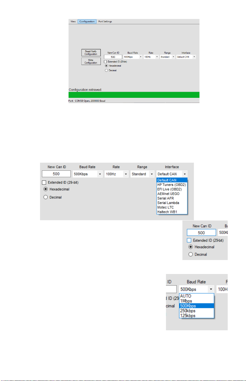
The AFR500CAN should be configured using the AFRCAN
Programmer software. CANbus message IDs, baud rate, data rate, and
other settings may be adjusted. There are options for choosing some
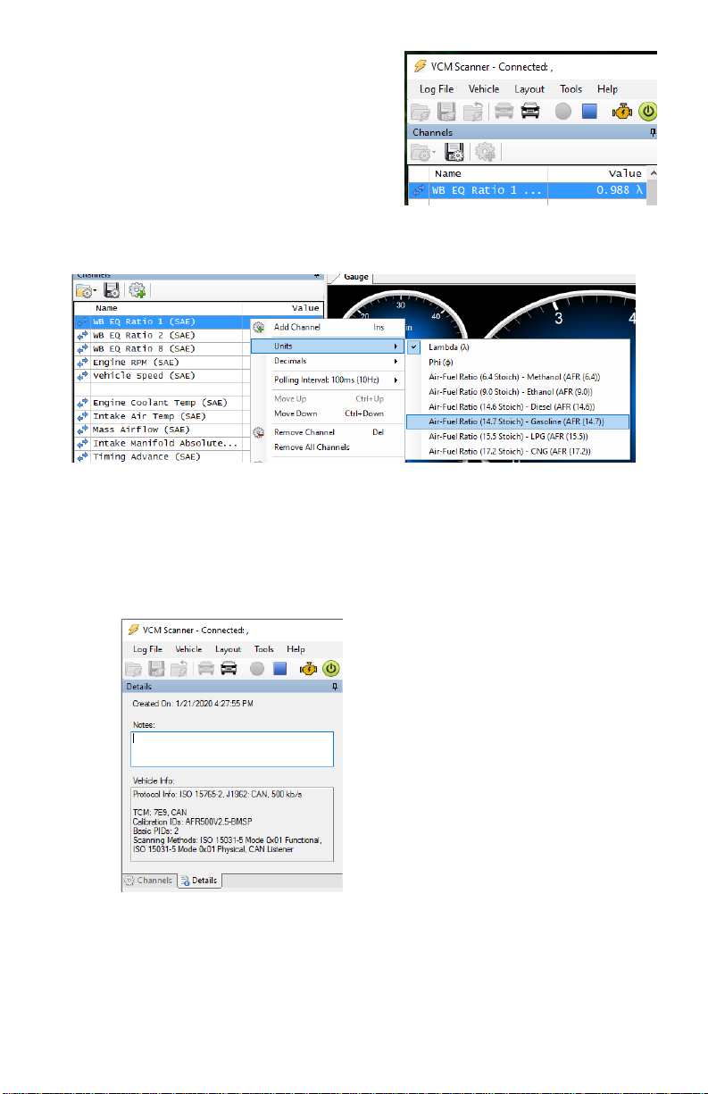
preprogrammed outputs for use with CAN Enabled ECUs, OBD2
ECU tuners, aftermarket gauges, dashes, & loggers.
3. New features in the AFR500CAN
The AFR500CAN is a major iteration on the AFR500V2. All
features & functions of the original AFR500V2 remain intact with the
added improvements below:
•OBD-II Compatibility. Works with most 2008 and newer CANbus
based systems.
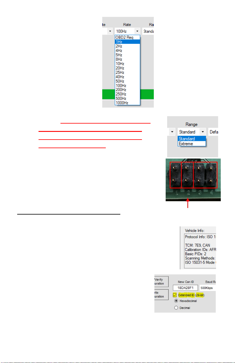
•CANbus output on IDs 1h-7FFh(11-bit) or 1h-1FFFFFFFh(29-bit)
•USB-CDC Serial Output for HPTuners & EFI Live Software
•AFRCAN Programmer software for:
-configure CAN interface
-configure CAN ID/bitrate/frequency/PID
-update AFR500CAN firmware
-configure AFR500 Range
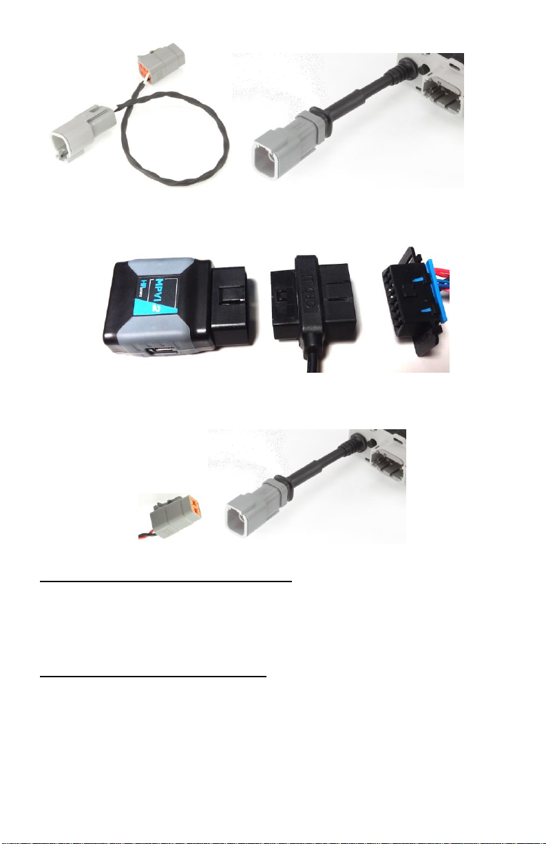
4. Kit Contents
• AFR500CAN Controller
• USB programming harness
•AFR500CAN Setup Manual
• 1 red CAN termination resister jumper contact
• CANbus adapter harness (Optional)
• Wideband oxygen sensor (Bosch LSU 4.2, 4.9, or NTK Sensors)

Ballenger Motorsports AFR500CAN Manual Rev 1.2
- 3 -
• 13ft (standard), 7ft, or 24ft wiring harness
•AFR500v2 Tuning Manual
• Weld-in sensor bung
• Screw-in sensor plug
• Adhesive backed hook & loop pair
• 3 red configuration jumper contacts
5. Functional Description
The wideband controller AFR500CAN can communicate the current
lambda O2 reading over can through OBD2 inline adapter or by
plugging into a CANbus expansion hub or ECU.
6. Wiring Installation
The DTM-6S wiring pinout follows:
3. White wire –CAN + high
4. Black wire –CAN - low
If not using a premade adapters harness, Pin 3: CAN+ high and Pin 4:
CAN- low should be used to connect to the CANbus.
For Haltech, Motec, AEMnet using the appropriate adapter harness
plug, you plug the 4 Way DTM connector into a receiving CANbus
connector or hub. Then plug the 6 Way DTM connector into the
DTM-6P USB/CAN connector coming from the back of the
AFR500CAN unit.

Ballenger Motorsports AFR500CAN Manual Rev 1.2
- 4 -
For OBDII setups (HPTuners and EFI live)
1. Plug in the OBDII adapter harness to your cars OBDII port,
then plug the device in to the adapter harness.
2. Plug the other end of the adapter harness with the 6 Way
connector into the DTM-6P USB/CAN connector coming
from the back of the AFR500CAN unit.
7. Setting & Explanation of Options
The AFR500CAN has an internal 120R terminating resistor that is
enabled using a jumper. It is installed by default from the factory.
8. AFRCAN Programmer Setup
The AFR500CAN may be configured using the AFRCAN
Programmer software. CANbus message IDs, baud rate, data rate, and
other settings may be adjusted. There are also options for choosing

Ballenger Motorsports AFR500CAN Manual Rev 1.2
- 5 -
some preprogrammed outputs for use with HPTuners, EFI Live, Serial
Out, AEMnet, Motec, Haltech, and Default CAN. Default CAN is
useful for programming into ECU Master and Megasquirt 3 ECUs.
Installation
1. Download the software at
bmotorsports.com/download/software/AFRCAN_Programmer
.exe . Double click "AFRCANProgrammer.exe" to install.
2. Once installed, Start the AFRCAN Programmer software.
3. Power up the AFR500CAN from a 12v power source using
the main harness. The AFR500CAN will not operate via USB
power.
4. Plug in the USB adapter harness to the AFR500CAN then to
your computer’s USB port.
5. Open the Port Settings and click refresh. Locate the COM Port
labeled “AFR USB”and click connect.
6. Next, click the "Connect" button, then click on the menu
"Configuration" to return to the main window.
Configuration
1. Before changing any settings, we must first retrieve the
current configuration, do this by clicking the button labeled
"Read/Verify Configuration", once successful the message
"Configuration Retrieved" will be displayed at the bottom.

Ballenger Motorsports AFR500CAN Manual Rev 1.2
- 6 -
2. The Interface drop down menu lets you choose an option
which will preconfigure the settings to that option's default
settings (ID, Baud, Rate). "Default CAN" defaults to a generic
message output structure for use with most stand-alone ECUs
(See Section 16. for message structures). “Serial AFR”and
“Serial Lambda”will output a signal over the included USB
cable for VCM Scanner serial wideband feedback.
3. CAN address ID: The first box is for
changing the CAN ID (Default is 0x500, 11
bit), there are options for displaying the ID in
hexadecimal or decimal and 11-bit or 29-bit
(Extended ID).
4. Baud Rate: The second box is a drop-
down menu for changing the CANbus
Baud Rate (Default is 500kbps).
5. Data Rate: The third drop down menu
is for selecting the Data Update Rate
(Default is 100Hz).

Ballenger Motorsports AFR500CAN Manual Rev 1.2
- 7 -
6. Range: The Range drop down MUST
match the Jumper 2 setting on the
AFR500 circuit board or the CAN
Output will be wrong!
7. No jumper = Standard (Default), 9.0-16.0
GASOLINE, 0.618-1.098 LAMBDA
Jumper = Extreme, 6.0-20.0 GASOLINE,
0.411-1.373 LAMBDA
9. HPTuners VCM Scanner Setup
Note: If you are having trouble connecting you
may need to change the CAN ID from the
default 7E5. Connect the VCM Scanner
without the AFR500C connected and go to the
“Details”tab to see you what CAN IDs are
being used by the vehicle. Usually the hex ID
is followed by “, CAN”(Note: OBD2
CAN IDs respond as the base ID plus
8 for example IDs 7E0-7E7 respond as
7E8-7EF). Some newer vehicles may
need to check the “Extended 29-Bit”
in AFR CANProgrammer.

Ballenger Motorsports AFR500CAN Manual Rev 1.2
- 8 -
1. With the HPTuners
USB cable plugged
in and the car
powered on, open
“VCM Scanner”and
click on the “Vehicle”menu then select “Connect”.
2. After connecting you will need to
add “WB EQ Ratio 1”to the
Channels window. First click on
the gear with the green “+”.
3. In the tree navigate to "OBD Controller: TCM (0x7E5)" [7E5
is default, ID may be programmed differently], "Engine",
"Fuel", "Open & Closed Loop", "Oxygen Sensors" and double
click on "WB EQ Ratio 1 (SAE)".
4. If “WB EQ Ratio (SAE)”doesn’t show up you may need to
click “Repoll For Supported Parameters”from the “Vehicle”
menu.

Ballenger Motorsports AFR500CAN Manual Rev 1.2
- 9 -
5. Next select “Start Scanning”
from the “Vehicle”menu. This
will start logging the vehicle
parameters, you will see
lambda values displayed in the
right column.
6. If you prefer to view AFR you can right click on "WB EQ
Ratio 1 (SAE)" and “Units”select the AFR for your fuel type.
Note that this may not match the AFR500CAN display whose
stoichiometric reference is 14.56 (Indolene Clear).
7. Near the bottom of the “Channels window is a tab labeled
“Details”which display the AFR500 controller properties and
CAN ID.

Ballenger Motorsports AFR500CAN Manual Rev 1.2
- 10 -
10. HPTuners Pre-CAN VCM Scanner USB Serial Setup
1. Plug in the AFR500C USB
programming/serial cable to your
computer.
2. Using Section 8 “AFRCAN Programmer
Setup”retrieve settings, then change the
“Interface”to “Serial AFR”for air-fuel-ratio,
or “Serial Lambda”for lambda.
3. With the HPTuners
USB cable plugged
in and the car
powered on, open
“VCM Scanner”and
click on the “Vehicle”menu then select “Connect”.
4. After connecting you will need to
add “AEM - AFR”or “AEM - EQ
Ratio”to the Channels window.
First click on the gear with the
green “+”.
5. In the tree navigate to "External Inputs", "Serial Port", "AEM"
and double click on "AEM - AFR”for air-fuel-ratio, or AEM -
EQ Ratio for lambda. (Note: this must correspond to the
“Serial AFR”or “Serial Lambda”Interface setting in
AFR CANProgrammer settings.)

Ballenger Motorsports AFR500CAN Manual Rev 1.2
- 11 -
6. Next select “Start Scanning”from the “Vehicle”menu. This
will start logging the vehicle parameters, you will see AFR or
lambda values displayed in the right column.
11. EFI Live Scan and Tune Setup
1. With Flashscan USB
cable plugged in and
the car powered on,
open “EFI Live Scan
and Tune”and click
on “F2: Scan”menu
then select “Auto
Detect”.
2. In the “Select
Controller”window
you can Select “Auto Detect”or right click on the “Right-click
to select trans-controller”and select “Ballenger Motorsports
AFR500V2 Bank 1”then click “OK”.
3. Under “Available PIDs”right-click on “WO2S11”then select
“Add”

Ballenger Motorsports AFR500CAN Manual Rev 1.2
- 12 -
4. Select the Menu “F3: Data”the click Yellow “Start
Monitoring Data”button and you will see the lambda value
under the “Value”column.
12. Haltech ECU Setup
1. With the AFR500CAN
connected and power
up, turn on the car to
power up the ECU and
open the Haltech
software and connect to the ECU.
2. Under the “Devices”tab you should see wideband (single
channel) saying “Device Found”. Click the “Options”pull
down and select “Enable Device”
3. The software will then
ask to reset the ECU and
after the wideband will
show up as “Online”
4. Under the “Inputs”then “Main”tab of the “Main Settings”
window the (analog) O2 Input should be set to “None”.

Ballenger Motorsports AFR500CAN Manual Rev 1.2
- 13 -
5. Under the “Inputs”and “Wideband Devices”tab, Wideband
(Single Channel) WB1 should be checked and pull-down label
“Wideband Sensor 1”should be selected.
13. Motec ECU Setup
1. From the “Adjust”menu select “General Setup”then
“Communication”then “CAN Setup”.
2. Under Parameter “CAN 1 Data”enter “1”for “PLM Receive”
3. Under “CAN 1 Address”enter the decimal address value
which by default is 1120 (460h).
4. The default “CAN 1 Transfer Rate”of 50 may be left alone.
14. Message Structure for Default CAN Setting
Table of contents