Bamo TURBISWITCH GS5 User manual

TURBISWITCHGS5
Turbidity Limit Value Evaluation Unit
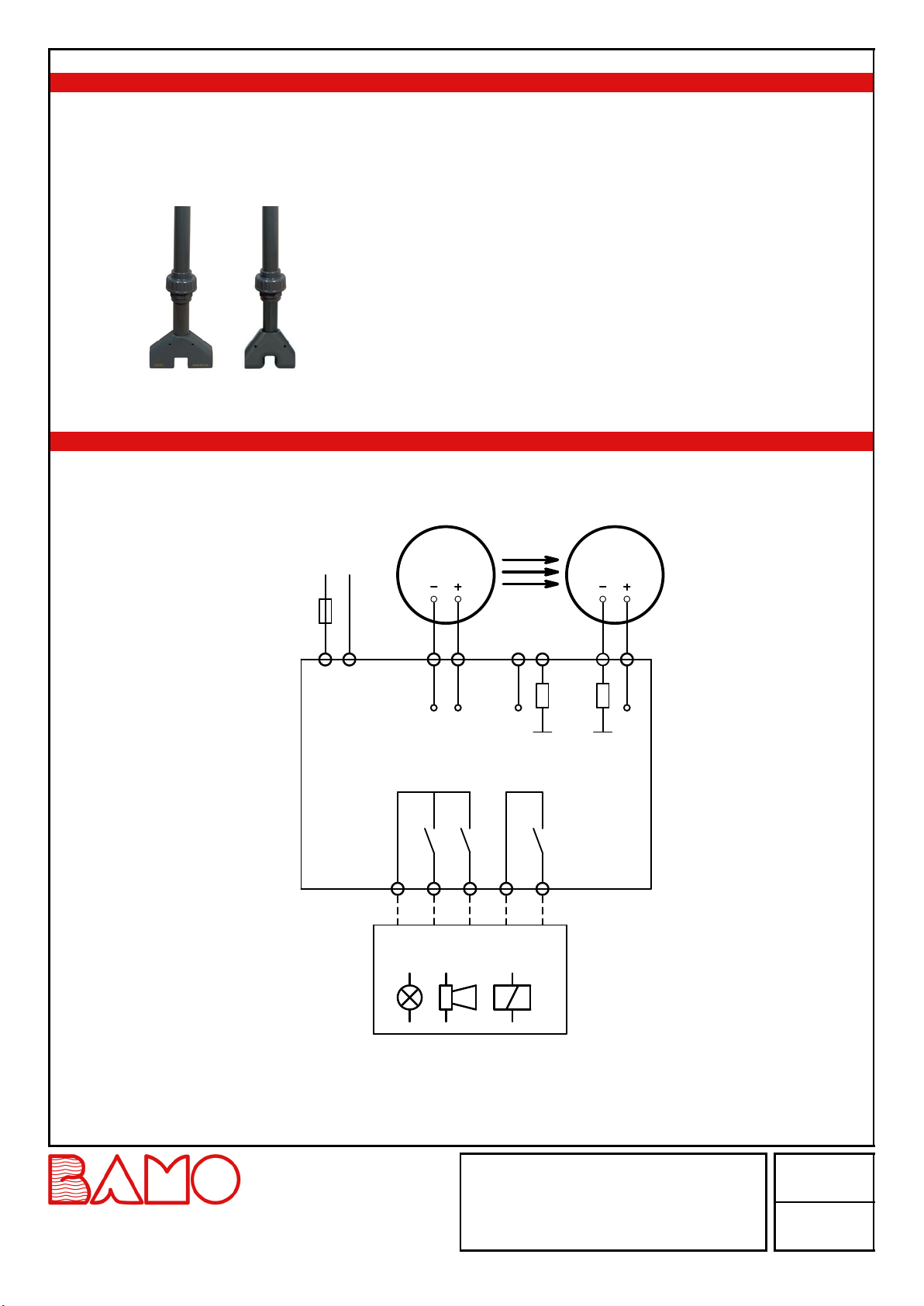
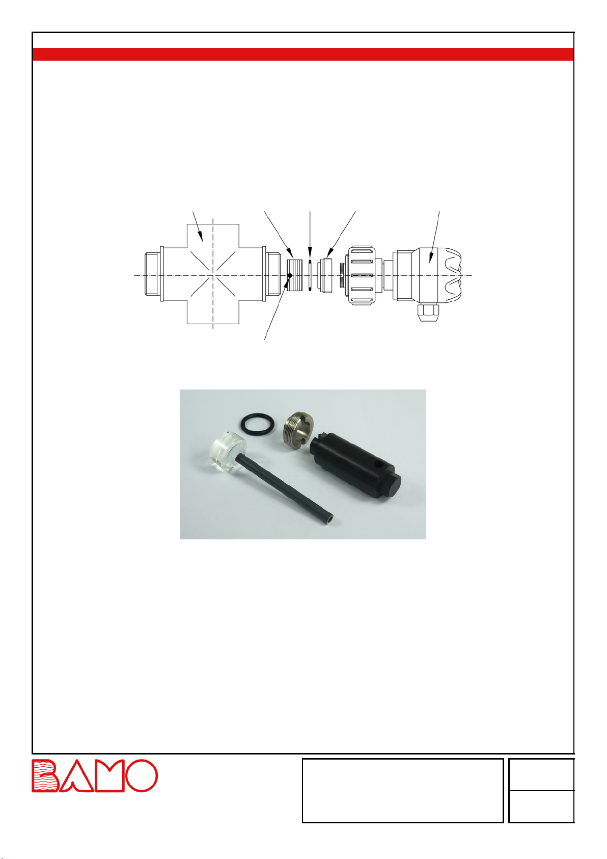
Evaluation Unit Measuring cells (in-line installation) Immersion Probes
SAFETY PRECAUTIONS
• Installation, initial start-up and maintenance may only be performed by trained personnel!
• The device may only be connected to supply power which complies with the specifications in the technical data and on the serial plate!
• The device must be disconnected from all sources of power during installation and maintenance work!
• The device may only be operated under the conditions specified in the operating instructions!
DESCRIPTION
The TURBISWITCHGS5 evaluation unit in conjunction with the associated transducers is an optical turbidity measurement for determining
the solid content in a liquid medium.
The turbidity signal is read out as an adjustable limit value via the evaluation unit.
The turbidity measurement is based on the optical absorption method, i.e. it reacts to light loss due to undissolved solids in the medium. Due to
clocked infrared light, the measurement is insensitive to external light.
If the measured turbidity value is exceeding or below the trigger point value, the output relay in the TURBISWITCHGS5 is actuated in
accordance with the settings.
Attention: Operation of the transducers of the TRUBOMAT series (TT-GS, TR-GS and CP1) at the evaluation unit
TURBISWITCHGS5 is not possible!
TECHNICAL DATA
Supply power 100...240VAC / 50...60Hz (TURBISWITCH GS5G) or
10...30VDC and 12...24VAC (TURBISWITCHGS5D)
Power consumption 1...5W
Ambient temperature -10...+45°C
Output relays 2x potential free limit value contact (normally open)
(turbidity value is exceeding or below the trigger point value)
1 x potential free fault contact (normally open)
All contacts are open when supply power is switched off!
Output relay switching capacity 250VAC, 3A / 30VDC, 1A
Note: Contacts are not protected against overload! Use external protective device!
Housing dimensions 22.5x100x122mm
Top-hat rail dimensions 35x7.5mm (DINEN60715)
Protection IP40
Connector terminals Screw terminals, max. 1.5mm²
Limit value 0…100% within 3 measuring ranges (depending on the solid content)
LOW (5% steps); MEDIUM (2% steps); HIGH (1% steps)
Reset hysteresis Adjustable 1…25% of the selected limit value
Cable length Max. 100m between sensor and evaluation unit
Display 2½-place LED, 5x7 pixel matrix display
Settings Rotary/pushbutton selector on front panel
Switching delay Adjustable 0.1…9.9seconds
CE Mark: The device fulfills the legal requirements of applicable EU-guidelines.
TUR
19-08-2021 M-410.03-EN-AA 410-03/1
Turbidity Limit Value
Evaluation Unit
TURBISWITCHGS5
22, Rue de la Voie des Bans · Z.I. de la gare · 95100 ARGENTEUIL
Tel
Fax
+33 (0)1 30 25 83 20
+33 (0)1 34 10 16 05
Web
E-mail
www.bamo.eu
INTERNATIONAL

DP0004a
DISPLAYS ON THE EVALUATION UNIT
Yellow LEDs: Selected measuring range: 1 LED = LOW / 2 LEDs = MEDIUM / 3 LEDs = HIGH
Blue LED: LED lit: Limit value exceeded; LED off: measurement below the limit
0-100: Selected limit value (%) in the specified measuring range
TR: Receiver malfunction or receiver not connected
TT: Emitter malfunction or emitter not connected
CR: Memory error (perform reset to factory settings)
ST: Default values (after reset to factory settings)
ER: Excessive number of transmission errors during digital transmission
HT: Permissible temperature range of the transducer exceeded
LT: Valid temperature of the transducer underrun
In the case of Measuring cells for piping systems (TURBISWITCHGA…), the green LEDs in the terminal housing of the TT-HDR emitter and
the TR-HDR receiver blink as long as internal measured value processing operates correctly (a continuously illuminated or red LED indicates a
fault).
LIMIT VALUE SWITCHING PERFORMANCE
The blue LED is off: turbidity of the medium is below the selected limit value. The relay for ’’Below limit value’’ is open.
The blue LED is lit: the limit value has been exceeded. The relay for “limit value exceeded” is open.
LIMIT VALUE ADJUSTMENT
Setting range: 3x 0...100% (LOW / MEDIUM / HIGH) by turning the rotary/pushbutton switch.
Note: Switching to the next higher or lower measuring range is accomplished by simply turning the rotary/pushbutton selector.
The selected hysteresis value is automatically skipped in this case. 100% in the LOW range is followed by 0% in the MEDIUM range.
100% in the MEDIUM range is followed by 0% in the HIGH range.
100% in the HIGH range is the highest possible limit value.
0% Low/Med/High
100% Low
100% Med
100% High
Overall Sensing Range
In the LOW range One yellow LED lights up
In the MEDIUM range Two yellow LEDs light up
In the HIGH range Three yellow LEDs light up
The limit value cannot be set to less than or equal to the currently selected reset hysteresis!
DELAY TIME "TD"
Adjustable from 0.1 to 9.9seconds (default value: 0.1second).
RESET HYSTERESIS "HY"
Setting range: 1 to 25% of the selected limit value.
The output relays are not switched back until the measured value decreased below the selected percentage of hysteresis
Reset hysteresis cannot be set to greater than or equal to the currently selected limit value!
The default setting for reset hysteresis is 1%.
TEMPERATURE MONITORING "TP" (TEMPERATURE PROTECTION)
Setting range: on/off
The connected probe is designed for a specific temperature range. If the permitted range is exceeded, this is indicated as an error. If this alarm
function is not desired, temperature monitoring can be deactivated (Off).
TUR
19-08-2021 M-410.03-EN-AA 410-03/2
Turbidity Limit Value
Evaluation Unit
TURBISWITCHGS5
22, Rue de la Voie des Bans · Z.I. de la gare · 95100 ARGENTEUIL
Tel
Fax
+33 (0)1 30 25 83 20
+33 (0)1 34 10 16 05
Web
E-mail
www.bamo.eu
INTERNATIONAL

DP0005a
FAULT CONTACT
The contact is always closed when measurement functions correctly.
The fault contact opens in the event of a fault in the connected sensor.
The type of fault is indicated at the display (TR: receiver fault, TT: emitter fault). If measured turbidity is significantly greater than the maximum
measuring range of the sensor, fault message TT (emitter fault) is displayed.
All contacts are always open in the event of a fault!
RESET TO DEFAULT SETTINGS
Switch power supply on!
Within 3seconds (i.e. during the test routine), press and hold the rotary/pushbutton selector for approximately 5seconds:
The display counts up: 1, 2, 3, 4... 99 ST (ST = default values are loaded).
All settings are returned to their default values (factory settings).
SWITCHING SUPPLY POWER ON (TEST ROUTINE)
After supply power has been switched on, the device starts a test routine during which all LEDs and the digital display are activated (LED test).
After about 5 seconds, the evaluation units software version is briefly displayed.
The display is then “limit value display”.
INSTALLING A MEASURING CELL IN A PIPING SYSTEM (IN-LINE)
Installation of in-line measuring cell
The Measuring cells (TURBISWITCHGA1, GA5, GA11) can be installed in main lines as well as in bypass lines.
Emitter
Receiver
Horizontal installation (top view)
Flow direction
Installation in bypass line (top view)
Flow direction
Emitter
Receiver
Flow direction
Flow direction
Emitter
Receiver
Emitter
Flow direction
Vertical installation Installation with trap
Emitter
Receiver
Measurable turbidity values depend on the process medium and the nominal diameter of the piping.
Minimum acquirable turbidity in the LOW range begins at roughly 50...100FAU.
Maximum detectable turbidity in the HIGH range: approx. 3000...10000FAU (corresponds to approx. 10...30g/l SiO₂).
Maximum detectable turbidity in the MEDIUM range: 10% of the HIGH range.
Maximum detectable turbidity in the LOW range: 1% of the HIGH range.
TUR
19-08-2021 M-410.03-EN-AA 410-03/3
Turbidity Limit Value
Evaluation Unit
TURBISWITCHGS5
22, Rue de la Voie des Bans · Z.I. de la gare · 95100 ARGENTEUIL
Tel
Fax
+33 (0)1 30 25 83 20
+33 (0)1 34 10 16 05
Web
E-mail
www.bamo.eu
INTERNATIONAL

DP0006a
INSTALLING A MEASURING CELL IN A PIPING SYSTEM (IN-LINE) / (Continuation)
To assure a reliable measurement please observe the following:
• The optical windows must be clean!
• The formation of gas bubbles in the medium should be prevented to avoid false measurements!
• The emitter and the receiver must always be aligned with the horizontal axis of the pipe when installed horizontally in order to avoid
incorrect measurements due to deposits on the glass discs (see picture below)!
E R
R
E
• Only a completely filled pipeline guarantees a correct measurement!
• It may be advisable to provide for back pressure by means of restriction, or to install a trap.
• Dried-on residues on the glass discs distort measurements, e.g. after an operating process was in standby.
• It is recommended to include straight pipe distances, upstream and downstream the measuring cell, of at least 3 to 5 times the diameter of
the pipe.
• When mounted in a trap, stop valves or/and drain valve should be installed for easy maintenance and removing the measuring cell.
• Use the supplied mounting kit (key tool and suction cup) in order to remove and install the glass discs. Observe torque! (Torque spanner
Turbiclick 5.7 optionally available, please contact us).
INSTALLING AND CONNECTING THE IMMERSION PROBE (CP2 or CP5)
Installing the immersion probe
The TURBISWITCHCP2 and CP5 transducers are designed as hanging probes or for use with an extension tube.
It can be installed in slurry tanks, basins or open wells.
The probe should be installed so that it can be easily removed for cleaning.
Gas bubbles cause false measurements!
The frequency of cleaning routines depends on operating conditions.
Do not scratch the optics when cleaning the sensors!
The following measuring ranges apply to the TURBISWITCHCP2 and CP5 transducers:
Minimum detectable turbidity in the LOW range: starts at roughly 100...300FAU
Maximum detectable turbidity in the HIGH range: approx. 30000FAU (corresponds to approx. 100g/lSiO₂)
Maximum detectable turbidity in the MEDIUM range: 10% of the HIGH range
Maximum detectable turbidity in the LOW range: 1% of the HIGH range
Installation of the immersion probe TURBISWITCHCP2 or CP5 variant ZK or Z0
CP2PVC CP5PP
The Z0 version is supplied without fitting accessories.
The ZK version is supplied with an angle bracket and its cable gland.
Please note: Caution with powerful flow, turbulences the cable must not be
overstretched!
In such cases, a cable or a rod may be used to secure the sensor (fixed on to the
two holes in the base of the sensor).
M6 threads can be tapped into the holes if necessary.
TUR
19-08-2021 M-410.03-EN-AA 410-03/4
Turbidity Limit Value
Evaluation Unit
TURBISWITCHGS5
22, Rue de la Voie des Bans · Z.I. de la gare · 95100 ARGENTEUIL
Tel
Fax
+33 (0)1 30 25 83 20
+33 (0)1 34 10 16 05
Web
E-mail
www.bamo.eu
INTERNATIONAL

AP0319a
INSTALLING AND CONNECTING THE IMMERSION PROBE (Continuation)
Installing the TURBISWITCHCP2 / CP5ZR immersion probe
CP2 CP5
For permanent installation in tanks or basins, the transducer TURBISWITCHCP2 /
CP5 is available with a detachable probe tube.
ELECTRICAL CONNECTION (HDR...)
For GA... measuring cells with transmitter / receiver TT-HDR and TR-HDR or TT-HDR5 and TR-HDR5
Emitter Receiver
IR Light
TT-HDR
Emitter
TURBISWITCHGS5
TR-HDR
Receiver
10 to 30 VDC
100 to 240 VAC
L(+) N(-)
Fuse
16 14 8 2 6 1 3 4
OC V+ RX V+
Limit value >>
Limit value <<
Fault
Signalling and Control Unit
9 11 12 13 15
Power supply
TUR
19-08-2021 M-410.03-EN-AA 410-03/5
Turbidity Limit Value
Evaluation Unit
TURBISWITCHGS5
22, Rue de la Voie des Bans · Z.I. de la gare · 95100 ARGENTEUIL
Tel
Fax
+33 (0)1 30 25 83 20
+33 (0)1 34 10 16 05
Web
E-mail
www.bamo.eu
INTERNATIONAL

AP0318b
AP0315a
ELECTRICAL CONNECTION (Immersion probe CP2 or CP5)
10 to 30 VDC
100 to 240 VAC
Shield (supply –)
L(+) N(+)
Fuse
16 14
Green (CP5 only)
Service wire
White (signal)
Brown (supply +)
may not be
connected
8 2 7 6 1 3 4
Power Supply
OC V+ UN RX V+
TURBISWITSCHGS5
Immersion
probeCP...
Limit value >>
Limit value <<
Fault
9 11 12 13 15
Signalling and Control Unit
SWITCHING LOGIC
Switching Logic
Limit value
exceeded and No
fault
Below the
limit value and No
fault
Measurement
impossible
and fault
9 11 12 13 15 9 11 12 13 15 9 11 12 13 15
Switching logic with increased reliability
The contacts open when one of the following events occur:
Contact 9-11 opens when the limit value is exceeded.
Contact 9-12 opens when measurements are below the limit value.
Contact 13-15 opens in the event of a fault.
Please note:
A connected PLC must react to the opening contact 13-15 in order to ensure a wire break monitoring.
If a fault occurs or in the event of power failure, all the contacts (9,11,12,13,15) are open.
TUR
19-08-2021 M-410.03-EN-AA 410-03/6
Turbidity Limit Value
Evaluation Unit
TURBISWITCHGS5
22, Rue de la Voie des Bans · Z.I. de la gare · 95100 ARGENTEUIL
Tel
Fax
+33 (0)1 30 25 83 20
+33 (0)1 34 10 16 05
Web
E-mail
www.bamo.eu
INTERNATIONAL

DP0003c
CONTROLS: ROTARY/PUSHBUTTON SELECTOR
Turn
In menu level 0 the selected limit value is displayed and can be changed.
In menu level 1 reset hysteresis (HY), delay time (TD) or temperature monitoring (TP) can be selected.
In menu level 2 desired values for reset hysteresis and delay time (0.1 to 9.9 seconds) can be selected.
Anticlockwise rotation: -
Clockwise rotation: +
Press
Press to select submenus.
Pressing the button in submenu 2 returns the display to menu 1.
Note:
Changed settings are saved immediately!
If the rotary/pushbutton selector is not operated for more than 7 seconds, the display returns automatically to menu level 0.
Menu structure
Turn switch
Press switch
LED Off
LED On
Threshold value display low Threshold value display med Threshold value display high
0-100 0-100
Hysteresis selection Time delay selection Temperature monitoring
Hysteresis 1...25% Time 0.1...9.9s on / off
back to
level 1
back to
level 1
back to
level 1
0
1
2
SETTING THE THRESHOLD, LIMIT VALUE AND COMMISSIONING
Adjustment takes place after installation and electrical connection.
If problems arise, see “Troubleshooting”.
All steps must be carried out in chronological order!
Detecting the transition from the clear phase to sludge:
1. Turn the rotary/pushbutton selector on the evaluation unit clockwise as far as it will go until the display indicates 100% in the HIGH range.
3 LEDs light up yellow.
2. Fill the measuring cell with the clear phase or immerse the probe into the clear phase (blue LED is off).
3. Turn the rotary switch anticlockwise (-) until the blue LED lights up.
4. Slowly turn clockwise (+) until the blue LED goes out.
The device now reacts as soon as the medium becomes slightly more turbid.
5. To prevent the TURBISWITCHGS5 from reacting to extremely slight deviations, adjust the switching point a bit further in the clockwise
direction (+) (approx. 5 to 20 %).
TUR
19-08-2021 M-410.03-EN-AA 410-03/7
Turbidity Limit Value
Evaluation Unit
TURBISWITCHGS5
22, Rue de la Voie des Bans · Z.I. de la gare · 95100 ARGENTEUIL
Tel
Fax
+33 (0)1 30 25 83 20
+33 (0)1 34 10 16 05
Web
E-mail
www.bamo.eu
INTERNATIONAL

SETTINGS THE THRESHOLD, LIMIT VALUE AND COMMISSIONING (Continuation)
Other settings and optimisation:
• If the ascertained limit value is below 10% in the HIGH or MEDIUM range, turn anticlockwise (-) to switch into the LOW range, thus
permitting a more accurate adjustment.
• In order to avoid inadvertent switching due to any brief occurrence of gas bubbles or particles, switching contact delay time (TD) can be
increased to as long as 9.9 seconds.
• Inadvertent switching in the event of switching point fluctuation can be avoided by increasing reset hysteresis (HY).
TROUBLESHOOTING
Error Cause Remedy
The blue LED is always on. The limit value is too low. Set a higher ‘’Limit value’’!
Reset hysteresis is too high. Set a lower ‘’Reset Hysteresis’’ value!
Turbidity exceeds the upper limit of the measuring range. Check the measuring cell for any impurities
(Especially if the measurement previously and remove them. Clean the glass
functioned in a permanently stable manner.) discs!
“TT” appears on the display Light from the emitter is not reaching the receiver. Check/ Mount the emitter and/or receiver
or to the measuring cell.
the HDR5 receiver blinks red. Check the measuring cell for any impurities
and remove them.
Clean the glass discs.
The turbidity value is so high, that no light is
reaching the receiver.
HDR5 emitter blinks red. Defective emitter. Replace the emitter.
“TR” appears on the display. The receiver has malfunctioned or it is not connected. Check the connection of the receiver!
“ER” appears on the display. Digital transmission between the receiver and the Check the cable, observe EMC
GS5 is severely impaired. environment, use a shielded cable.
“CR” appears on the display. An internal memory error has occurred. Reset to factory settings!
“HT” appears on the display. The maximum permissible temperature of the Comply with permissible temperature or
connected sensor has been exceeded. switch off temperature monitoring in the
TP menu!
“LT” appears on the display. The minimum permissible temperature of the Comply with permissible temperature or
connected sensor has been fallen short of. switch off temperature monitoring in the
TP menu!
The switching point has shifted. Deposits on the optical windows. Clean the glass discs!
The liquid level is too low. Fill the measuring cell or immerse the
probe!
An incorrect turbidity range has been selected. Change the turbidity range!
The limit value is too low or too high. Adjust the limit value!
TUR
19-08-2021 M-410.03-EN-AA 410-03/8
Turbidity Limit Value
Evaluation Unit
TURBISWITCHGS5
22, Rue de la Voie des Bans · Z.I. de la gare · 95100 ARGENTEUIL
Tel
Fax
+33 (0)1 30 25 83 20
+33 (0)1 34 10 16 05
Web
E-mail
www.bamo.eu
INTERNATIONAL

MAINTENANCE
In-line measuring cells:
• Dirty glass discs must be cleaned to insure a correct measurement.
• The TURBISWITCHGA… measuring cell is supplied with a key tool for loosening the compression disc.
• The glass disc is removed from the cell with the suction cup.
• Drain the measuring cell completely before performing any maintenance or cleaning work!
• Do not use any objects or cleaners that might damage the glass disc!
• Lime scale can be removed with available light limescale remover.
• The side of the glass disc marked with a dot must be installed that it faces the medium!
• Check the seals (O-rings) for damage and replace them if necessary before start-up!
• The frequency of cleaning routines depends on operating conditions.
Measuring cell Glass disc O-ring Compression disc Emitter or receiver
The side with the dot has an anti-fouling coating. Install this side that it faces the medium!
TUR
19-08-2021 M-410.03-EN-AA 410-03/9
Turbidity Limit Value
Evaluation Unit
TURBISWITCHGS5
22, Rue de la Voie des Bans · Z.I. de la gare · 95100 ARGENTEUIL
Tel
Fax
+33 (0)1 30 25 83 20
+33 (0)1 34 10 16 05
Web
E-mail
www.bamo.eu
INTERNATIONAL
Table of contents