B&G electronics PW-150 User manual
PW-150 V5.1
PLEASE READ BEFORE USING THE EQUIPMENT
EN 1.9
INSTALLATION AND OPERATION MANUAL
English
INTERCOM SYSTEM FOR PUBLIC SAFETY AND STEALTH
ARMORED VEHICLES.
PW-150

PW-150 V5.1 2
PW-150 V5.1 2
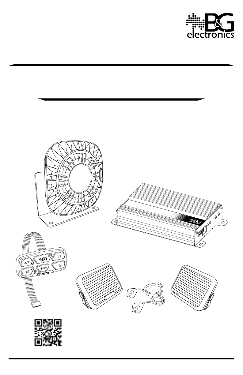
COMPONENTS AND RECOMMENDED LOCATIONS IN THE VEHICLE
(1) Electronic unit
(1) Control keyboard & internal microphone
(1) 150W loudspeaker
(2) External microphones
(2) Internal speakers
(1) Keyboard harness
(1) Power cable (battery)
(1) Fuse 25A
(2) Speaker extension cables
(1) Loudspeaker and auxiliary load harness
(1) Hand microphone (optional)
(1) Hand microphone holder (optional)
CONTROL KEYPAD
& INTERNAL MIC
ELECTRONIC UNIT
PW-150
EXTERNAL MICINTERNAL SPEAKER
EXTERNAL MICINTERNAL SPEAKER
150W
LOUDSPEAKER
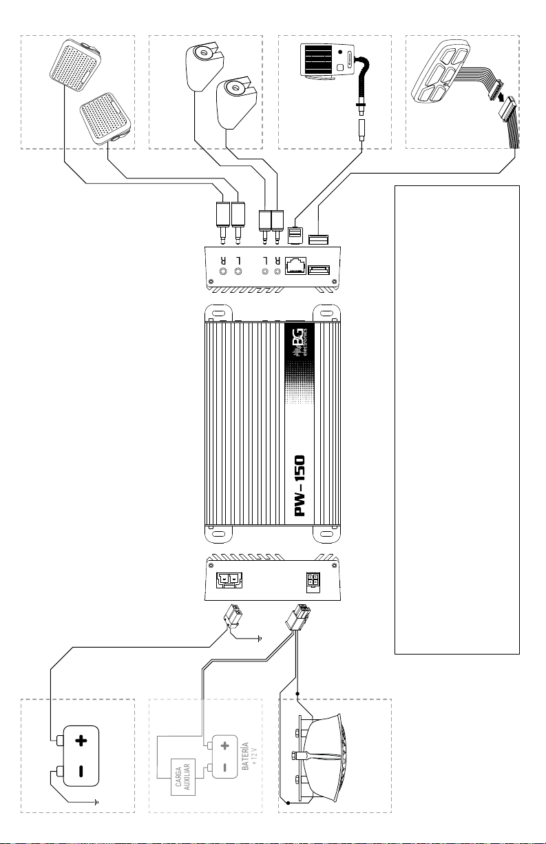
INSTALLATION AND ELECTRIC DIAGRAM
To install the equipment, see the wiring diagram shown further on.
Avoid leaving visible cables in the cabin to maintain the vehicle’s aesthetics unaffected.
If there are any cables left disconnected, insulate them with tape; disconnected cables
making an undesired contact can cause a malfunction.
PW-150
Electronic Unit
Place it on a hidden location for aesthetic purposes. Make sure that the location
allows some ventilation into the unit to avoid overheating.
Digital Keyboard
To facilitate the handling of the equipment, place the keyboard on a location within
the driver’s reach, such as the console of the vehicle. Clean the surface where the
keyboard is to be sticked to ensure an adequate adherence. Remove the protective
liner from the adhesive pad in the back side and stick it to the surface.
To clean the keyboard, gently wipe it with a dry cloth. Do not use water or any solvent.
Loudspeaker
When selecting the location for the loudspeaker, keep in mind that this component is
weather resistant but it is not immersion-proof. The loudspeaker must be placed as far
as possible from the keyboard (where the internal microphone is) to prevent feedback.
Splice and tape the loudspeaker wires to the output wires (they have no polarity).
External Microphones
Two locations are recommended for installation, as explained on the next page.
Internal Speakers
Place them at opposing sides inside the vehicle to get a stereo sound. Locate the
speakers out of view without affecting the sound.
Hand microphone (optional)
Place the hand microphone holder within easy reach of both driver and passenger.
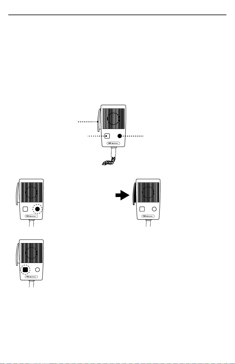
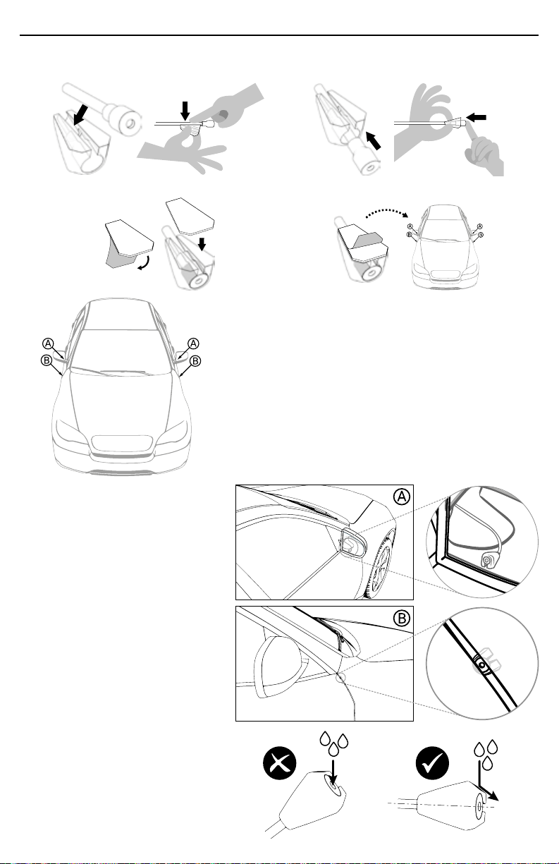
EXTERNAL MICROPHONES INSTALLATION INSTRUCTIONS
Each microphone includes a shell to hold
it in place and protect it from outdoor.
Depending on the installation procedure,
it can be more convenient to assemble
microphone and shell either before or
after the wiring. For instance, if the wiring
requires to pull the cable through a narrow
space, it is recommended to assemble after
wiring.
Shell
Microphone
Mounting
tape

PW-150 V5.1 3
PW-150 V5.1 3
Microphone + shell assembly procedure
1.Insert the cable in the shell by pressing it with your fi nger. 2.Push the microphone into the shell (do not pull the cable!).
3.Remove the liner from the tape and stick it to the shell. 4.Stick the shell on the selected surface, previously cleaned
with alcohol.
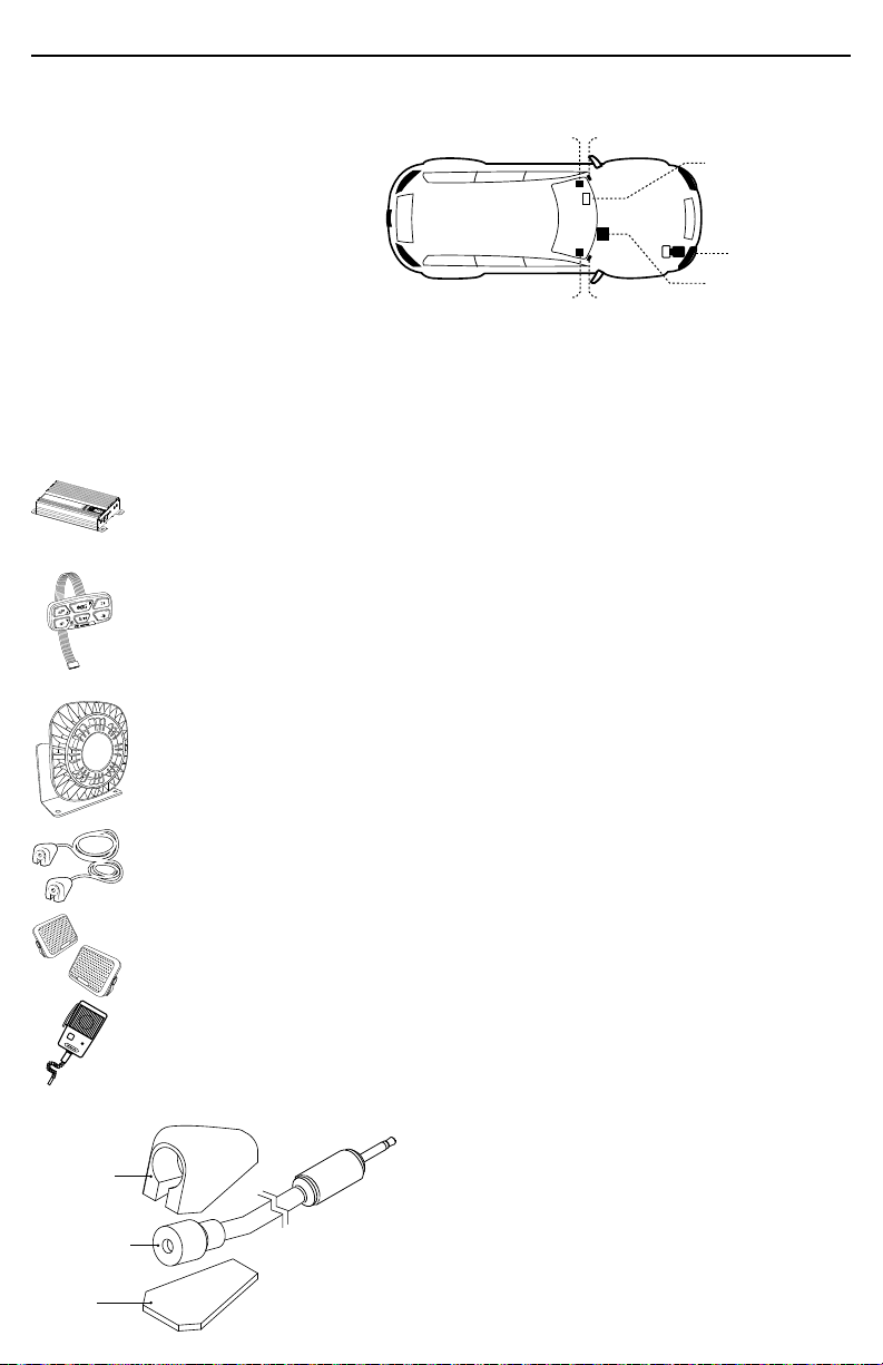
Recommended locations to install the microphones
There are two recommended locations in the vehicle
(see fi gure to the left), they differ with regard to ease
of installation and audio reception volume.
You can select a location according to your
preferences.
Location A
Inside the rearview mirror.
This location offers the highest
volume yet the most time
consuming installation, as it
requires to take parts of the
vehicle apart.
Location B*
In the gap of the front doors.
Select a surface to place the
microphone so that it faces to
the exterior from inside the gap.
Once the surface is selected,
the installation is fairly easy.
* WARNING!
Place the microphone
slightly downward to prevent
damage from water clogging.

Fasten connector
to a fixed point
EXTERNAL MIC
(L-R)
WARNING!
Gently handle the wires during the installation; pressing or forced bending of the wires can cause
internal damage and subsequent malfunction.
Avoid placing the wires near from noise sources such as alternators, high tension wires, etc.
If there are any cables left disconnected, insulate them with tape; disconnected cables making an
undesired contact can cause malfunction.
Do not manipulate the loudspeaker terminals.
Red
Black
White
EXTERNAL
LOUDSPEAKER
BATTERY
+ 12 V
INTERNAL SPEAKER
(L-R)
DIGITAL
KEYBOARD
WIRING DIAGRAM
PW-150
HANDHELD MIC
(OPTIONAL)
1
Splice and tape the loudspeaker wires to the output wires (they have no polarity).
AUXILIARY
LOAD
BATTERY
+ 12 V
Grey
11
Blue Brown
Grey
PW-150 V5.1 5
PW-150 V5.1 5
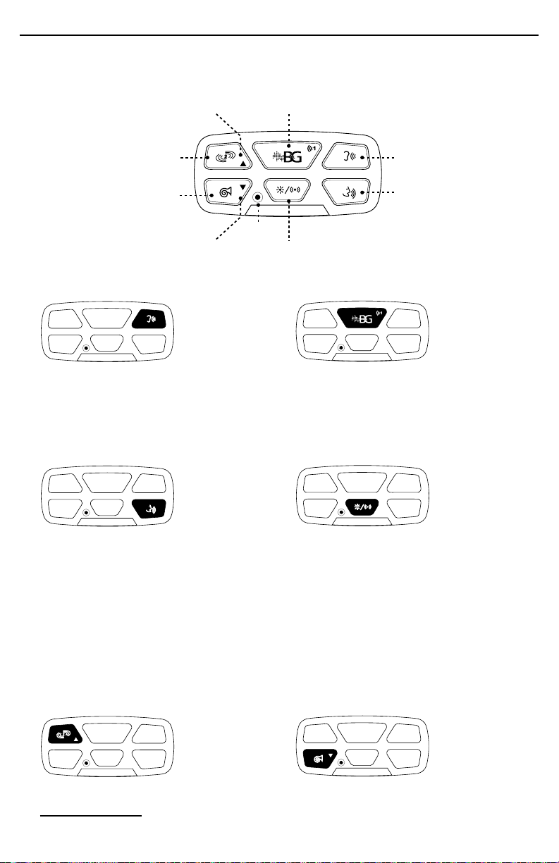
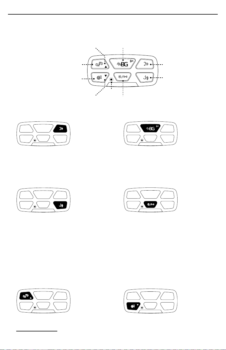
OPERATING PROCEDURES
All of the equipment’s functions are managed through a six button keyboard (see fi gure
below). Press the buttons with your fi ngertips, do not use objects to press them.
MIC
Volume DOWN
PTT
HORN
Manual WAIL INTER
SIRENVolume UP
AUX
ACTIVATING FUNCTIONS
Intercom* Siren - SIREN tone
ON: press & release
OFF: press &
release
ON: press & release
OFF: press & release
INTER enables hearing exterior sounds
through the interior speakers.
If during 5 minutes the equipment does
not detect any activity, INTER function
turns off (Automatic Shut Down, ASD).
Activates the reproduction of the tone
selected for SIREN.
Public Address “PA”* Auxiliary
ON: press & hold
OFF: release
ON: press & release
OFF: press & release
PTT allows the driver to communicate
to the exterior through the keypad
microphone.
For a more private communication (lower
exterior volume: PTT/INTER), press PTT
while in INTER mode. For a more public
communication (louder exterior volume:
PTT/PA), press PTT while in SIREN, AUX
SIREN or stand-by (with INTER off) mode.
Both volumes are set following the same
keypad procedure.
AUX function either turns on an auxiliary
siren tone “AUX SIREN” or activates an
auxiliary load “AUX LOAD”, depending on
the subfunction assigned to it.
Keypad light fl ashes once every 2 seconds
when AUX LOAD is on.
Siren - WAIL tone Siren - HORN tone
ON: press & hold
OFF: release
ON: press & hold
OFF: release
Activates the reproduction of the WAIL
siren tone. Activates the reproduction of the HORN
tone.
If acoustic feedback occurs while INTER or PTT are on, AFC (Automatic Feedback Control) will trigger to prevent
feedback. AFC is further explained ahead in this manual.
*

PW-150 V5.1 6
PW-150 V5.1 6
SIREN tone selection
SIREN function allows to choose among 5 different tones: WAIL, Hi-Lo, PHASER, CHIRP
and YELP.
1.Activate SIREN. 2.While SIREN is sounding press WAIL repeatedly to switch to
the available tones (WAIL, Hi-Lo, PHASER, CHIRP and YELP).
AUX SIREN tone selection
With AUX set to AUX SIREN, it is possible to select the AUX SIREN tone to one of the
available tones (WAIL, Hi-Lo, PHASER or YELP).
It is not possible to set the same tone for both SIREN and AUX SIREN, meaning that while
setting AUX SIREN, the SIREN tone in use will be unavailable; also, if the AUX SIREN tone is
selected for SIREN, AUX SIREN’s tone will automatically change.
1.Activate AUX SIREN. 2.While AUX SIREN is sounding press WAIL repeatedly to switch to
the available tones (WAIL, Hi-Lo, PHASER, CHIRP and YELP)
NOTE: WAIL does not sound when SIREN / AUX SIREN is on.
SETTING UP FUNCTIONS
Setting up HORN tone
The default tone is Standard HORN, although the equipment allows to choose between
Standard HORN and B&G HORN, as explained below.
1.Press and hold HORN. 2.While HORN is held, press and hold
SIREN until the tone changes.
3.To change tone again, repeat steps
1 & 2.
Setting up AUX
AUX allows to either play an auxiliary siren tone, or change the activation state of an
auxiliary load up to 15 Amp (useful to control a light set or other device).
1.Press and hold AUX.
If it beeps once or twice, it’s set
to AUX LOAD. If siren stops &
restarts, it’s set to AUX SIREN.
2.Press SIREN to switch among AUX LOAD and AUX
SIREN.
If it beeps once or twice, it’s set to AUX LOAD.
If siren sounds, it’s set to AUX SIREN.
3.Press AUX to fi nish setup.
Upon fi nishing beeps twice.
Setting up AUX LOAD
With AUX set to AUX LOAD, it is possible to set AUX LOAD in a way that it gets activated
together with SIREN (for instance, that when SIREN sounds, a light set associated to AUX
LOAD turns on)*, in addition to the activation by pressing AUX.
1.Press and hold AUX until you hear 1
or 2 beeps.
2.Press HORN to switch AUX LOAD mode.
If it beeps once, it’s set to independent.
It it beeps twice, it turns on with SIREN.
3.Press AUX to fi nish setup.
Upon fi nishing beeps twice.
By default, AUX LOAD is set to activate independently from SIREN.*

PW-150 V5.1 7
PW-150 V5.1 7
Setting the volume of the internal speakers, “internal volume”
1.While INTER is on, press and hold
INTER.
2.While INTER is held, press WAIL to
increase volume.
3.While INTER is held, press HORN to
decrease volume.
External Volume Auto-Adjustment (VAA)
In addition to the manual adjustment, the equipment is capable of detecting the vehicle’s
level of acoustic isolation and adjust the maximum external volume accordingly.
To perform this procedure, close all of the vehicle’s doors and windows, and follow the
steps explained below.
To cancel the procedure at any moment press PTT.
1.Press and hold PPT.
Remain silent during the procedure.
2.While PTT is held, press INTER.
Release both upon hearing a beep.
3.Wait up to 30 s, the equipment will
beep 2 times when VAA has fi nalized.
Setting the volume of the external loudspeaker, “external volume”
1.Press and hold PTT. 2.While PTT is held, press WAIL to
increase volume.
3.While PTT is held, press HORN to
decrease volume.
NOTE: If INTER is on, PPT/INTER volume will adjust. If INTER is off, PTT/PA volume will
adjust.
Setting backlight keyboard
The backlight keyboard can be confi gure in two modes:
MODE 1: The keyboard backlights whenever a function is running, or the supply voltage
is high enough.
MODE 2: The keyboard backlights only while a button is pressed.
To switch between these modes follow the next steps:
1.Press and hold INTER. 2.While INTER is held, press and hold
SIREN.
3.Keep both buttons pressed for 5
seconds, a beep will sound when the
mode change is done.
AUTOMATIC FEEDBACK CONTROL (AFC)
If acoustic feedback would occur while PTT or INTER are on (caused, for instance, by the
opening of a door or window), the equipment will detect and automatically fi x the issue by
decreasing the volume. After the event takes place, the equipment will attempt to rise the
volume back to the level defi ned by the user, as long as AFC is not triggered again.
ENERGY SAVING FEATURES (Automatic Shut Down, ASD)
Partial Shut Down (PSD)
The equipment constantly tracks the incoming voltage status. If the incoming voltage
drops below 13 VDC, after 20 seconds of inactivity the equipment activates PSD mode.
This change is indicated by the turning off the keyboard’s backlights. While on PSD mode,
PW-150 V5.1 8
PW-150 V5.1 8
upon pressing any key the respective function will execute normally and the equipment
will return to normal energy consumption mode.
Total Shut Down (TSD)
If the incoming voltage drops below 11 VDC, after 60 seconds the equipment will
automatically shut down any function and auxiliary load. While on TSD, upon pressing any
key the backlights will blink 3 times and the function controlled by the pressed key will not
execute.
Once the equipment detects that the incoming voltage exceeds 12.5VDC again, the
equipment will return to its normal operation.
HAND MICROPHONE (OPTIONAL)
The microphone has 3 buttons to control public address and siren functions.
PTT
HORNSIREN 2
Siren - HORN tone Public address - PTT
ON: press & hold
OFF: release
Activates the
reproduction of the
HORN tone.
ON: press & hold
OFF: release
Allows the driver to
communicate to the
exterior through the
hand microphone.
Siren - SIREN 2 tone
ON: press & release
OFF: press & release
Activates the
reproduction of the tone
selected for SIREN 2.
Setting up SIREN 2 tone
SIREN 2 function allows to choose among 5 different tones (WAIL, Hi-Lo, PHASER, CHIRP,
and YELP). The selection of a SIREN 2 tone is independent from the other sirens, so that
changing tones for SIREN or AUX SIREN will not affect SIREN 2. To set up the SIREN 2 tone,
follow the procedure described below.
1. Press and hold SIREN 2, this will change the tone to the next option.
2. Release SIREN 2 to save the heard confi guration.

PW-150 V5.1 9
PW-150 V5.1 9
TECHNICAL SPECIFICATIONS
DIMENSIONS
Electronic Unit 37 H x 109 W x 198 D mm 1.5’’H x 4.3’’W x 7.8’’D
Loudspeaker 182 H x 165 W x 87 D mm 7.1’’H x 6.4’’W x 3.4’’D
Keyboard Control 25 H x 7 W x 54 D mm 1.0’’H x 0.3’’W x 2.1’’D
Internal Speakers 80 H x 56 W x 95 D mm 3.2’’H x 2.2’’W x 3.7’’D
INPUT VOLTAGE 11.5 - 14.8 VDC
INPUT CURRENT PW-150: 13 Amps @ 13.6 VDC
STAND BY CURRENT <25 mA
AUDIO FREQUENCY 330Hz - 5600 kHz
OUTPUT POWER PW-150: 142W RMS - 8 Ohm
SIREN FREQUENCY 440 - 1750 Hz
LOW VOLTAGE SHUTDOWN If voltage drops below 11 V for 60 seconds or longer, the equipment will cease
to work and resume operation when the system voltage is above 13V
MAX. LOAD 10 A
B&G ELECTRONICS
ONE YEAR LIMITED WARRANTY
B&G Electronics guarantees that this product leaves the factory free from defects related to materials
and manufacturing. If for any reason a failure related to materials and manufacturing were to occur
during the warranty period after the date of purchase, B&G Electronics would repair or replace the failing
equipment at the factory.
This warranty does not cover damage caused by mishandling, improper operation, fungible components,
or improper installation. This warranty does not cover physical damage to the surface of the product, or
damage caused by use of the product in conjunction with other products or accessories not designed by
B&G Electronics.
Keep the purchase receipt for the entire duration of the warranty period.


FAVOR LEER ESTE MANUAL ANTES DE USAR EL EQUIPO
ES 1.9
MANUAL DE INSTALACIÓN Y OPERACIÓN
Español
PW-150 V5.1
SISTEMA DE INTERCOMUNICADOR Y SIRENAS PARA
VEHÍCULOS BLINDADOS.
PW-150
PW-150 V5.1 12
PW-150 V5.1 2
COMPONENTES Y UBICACIÓN DENTRO DEL VEHÍCULO
(1) Unidad electrónica
(1) Teclado digital de control y micrófono interno
(1) Bocina de 150W
(2) Micrófonos externos
(2) Parlantes internos
(1) Arnés de teclado
(1) Arnés de potencia (batería)
(1) Fusible 25A
(2) Cables de salida de parlantes
(1) Arnés de bocina y carga auxiliar
(1) Micrófono de mano (opcional)
(1) Soporte de micrófono de mano (opcional)
TECLADO DE CONTROL
Y MICRÓFONO INTERNO
UNIDAD ELECTRÓNICA
PW-150
MICRÓFONO EXTERIORPARLANTE INTERNO
MICRÓFONO EXTERIORPARLANTE INTERNO
BOCINA
150W
INSTALACIÓN Y DIAGRAMA ELÉCTRICO
Para instalar el equipo consulte el diagrama de conexiones mostrado más adelante.
Evite dejar cables visibles dentro de la cabina que afecten la estética del vehículo.
En caso de que queden cables desconectados, aísle los cables con cinta eléctrica; cables
desconectados que hagan contactos no deseados podrían ocasionar fallas en el equipo.
PW-150
Unidad Electrónica
Debe ubicarse en un sitio oculto por motivos estéticos. Asegúrese de elegir una
ubicación con sufi ciente ventilación para prevenir sobrecalentamiento.
Teclado Digital
Para facilitar el manejo del equipo, ubique el teclado en un sitio al alcance de la mano
del conductor. Limpie la superfi cie donde se ubicará el teclado para asegurar una buena
adherencia. Retire la película de protección de la cinta adhesiva ubicada al respaldo y
fi je a la superfi cie elegida haciendo presión.
Para realizar la limpieza del teclado, frote suavemente con un paño seco. No utilice
agua ni solventes sobre el teclado.
Bocina
Al elegir la ubicación para la bocina tenga en cuenta que este componente resiste a
la intemperie pero no a la inmersión. La bocina debe ubicarse lo más lejos posible del
teclado (donde se encuentra el micrófono interno) para evitar la realimentación.
Empalme y encinte los cables de la bocina con los cables de salida (no tienen polaridad).
Micrófonos externos
Se recomiendan dos ubicaciones para su instalación, como se explica en la siguiente
página.
Parlantes Internos
Ubique en lados opuestos para conseguir un sonido estéreo. Procure ubicar los
parlantes fuera de la vista pero sin que se afecte el sonido.
Micrófono de Mano (opcional)
Ubique el soporte del micrófono en un lugar al alcance de la mano, tanto del conductor
como del copiloto.
INSTRUCCIONES DE INSTALACIÓN PARA LOS MICRÓFONOS EXTERNOS
Cada micrófono incluye una carcasa para
sujetarlo en su sitio y protegerlo de la
intemperie. Dependiendo del proceso de
instalación, puede ser más conveniente
ensamblar micrófono y carcasa antes o
después de cablear.
Por ejemplo, si el cableado requiere pasar el
cable por un espacio estrecho, se recomienda
ensamblar después del cableado.
Carcasa
Micrófono
Cinta
adhesiva
PW-150 V5.1 13
PW-150 V5.1 3
Ensamblaje micrófono + carcasa
1.Inserte el cable en la carcasa presionando con el dedo. 2.Empuje el micrófono dentro de la carcasa (¡no tire del cable!).
3.Retire el protector y pegue la cinta a la carcasa. 4.Pegue a la superfi cie seleccionada, limpiada previamente con
alcohol.
Ubicaciones recomendadas para instalar los micrófonos
Se recomiendan dos puntos en el vehículo (ver fi gura a la
izquierda), se diferencian con respecto a la facilidad de
instalación y el volumen de recepción de sonido.
Puede elegir una ubicación de acuerdo a sus preferencias.
Ubicación A
Dentro del espejo retrovisor.
Esta ubicación ofrece el mayor
volumen pero el tiempo de
instalación más largo, ya que
requiere desarmar partes del
vehículo.
Ubicación B*
En la ranura de la puerta frontal.
Elija una superfi cie para ubicar
el micrófono, de tal forma que
éste apunte al exterior desde
dentro de la ranura. Una vez
seleccionada la superfi cie, la
instalación es bastante fácil.
* ¡ADVERTENCIA!
Ubique micrófono levemente
inclinado para prevenir daños
provocados por acumulación
de agua.
Asegure el conector
a un lugar fijo
MICRÓFONOS
EXTERNOS (L-R)
¡ADVERTENCIA!
Manipule los cables con cuidado durante la instalación; presionar o doblar forzadamente los cables
podría causar daños internos y ocasionar fallos.
Evite ubicar los cables cerca de fuentes de ruido como alternadores, cables de alta tensión, etc.
Si algún cable quedara desconectado, aísle el cable con cinta. Cables sueltos haciendo contactos
indeseados podrían ocasionar fallos.
No manipule las borneras de la bocina.
CARGA
AUXILIAR
Rojo
Negro
Blanco
BOCINA
EXTERIOR
BATERÍA
+ 12 V
Gris
PARLANTES INTERNOS
(L-R)
TECLADO
DE CONTROL
DIAGRAMA DE CONEXIONES
PW-150
MICRÓFONO DE MANO
(OPCIONAL)
11
1
Empalme y encinte los cables de la bocina con los cables de salida (no tienen polaridad).
BATERÍA
+ 12 V
Gris
Azul Café
PW-150 V5.1 15
PW-150 V5.1 5
FUNCIONAMIENTO
Las funciones del equipo se manejan a través de un teclado de seis botones (ver fi gura
debajo). Presione los botones con las yemas de los dedos; no use objetos para presionar
los botones.
MIC
Bajar volumen
PTT
HORN
INTER
SIRENSubir volumen
AUX
Manual WAIL
ACTIVACIÓN DE FUNCIONES
Intercomunicador* Sirena - tono SIREN
ENCENDER:
pulsar y soltar
APAGAR:
pulsar y soltar
ENCENDER:
pulsar y soltar
APAGAR:
pulsar y soltar
La función INTER permite escuchar los
sonidos del exterior a través de los parlantes
internos. Si no se detecta actividad durante 5
minutos, INTER se apaga automáticamente
(Automatic Shut Down, ASD).
Activa la reproducción del tono SIREN
seleccionado.
Perifoneo “PA”* Auxiliar
ENCENDER:
mantener
presionado
APAGAR: soltar
ENCENDER:
pulsar y soltar
APAGAR:
pulsar y soltar
PTT permite al conductor comunicarse con
el exterior a través del micrófono del teclado.
Para una comunicación más privada (menor
volumen externo: PTT/INTER), oprima PTT
estando en INTER. Para una comunicación
máspública(mayorvolumenexterno:PTT/PA)
oprima PTT estando en SIREN, AUX SIREN o
stand-by (es decir, con INTER apagado).
Ambos volúmenes se confi guran siguiendo
el mismo procedimiento de teclado.
Dependiendo de la función que se le haya
asignado, AUX activa ya sea el tono de
sirena “AUX SIREN”, o la carga auxiliar
“AUX CARGA”.
La luz del teclado parpadea una vez cada
2 segundos cuando la carga auxiliar está
activada.
Sirena - tono WAIL Sirena - tono HORN
ENCENDER:
mantener
presionado
APAGAR: soltar
ENCENDER:
mantener
presionado
APAGAR: soltar
Activa la reproducción del tono WAIL. Activa la reproducción del tono HORN.
Si se presentara realimentación acústica cuando INTER o PTT están activos, AFC (Automatic Feedback Control)
se activará para prevenir la realimentación. AFC se explica en mayor detalle más adelante.
*

PW-150 V5.1 16
PW-150 V5.1 6
Selección del tono SIREN
La función SIREN permite elegir 5 tonos diferentes: WAIL, Hi-Lo, PHASER, CHIRP y YELP.
1.Active SIREN 2.Mientras suena SIREN pulse WAIL repetidamente para cambiar
entre los tonos disponibles (WAIL, Hi-Lo, PHASER, CHIRP Y YELP).
Selección del tono AUX SIREN
Una vez establecido AUX SIREN como función AUX, es posible seleccionar el tono para
AUX SIREN entre los tonos disponibles (WAIL, Hi-Lo, PHASER, CHIRP o YELP).
No es posible seleccionar el mismo tono para SIREN y AUX SIREN, esto signifi ca que al
estar eligiendo AUX SIREN el tono activo en SIREN no estará disponible; del mismo modo,
si el tono AUX SIREN es seleccionado para SIREN, el tono AUX SIREN cambia.
1.Active AUX SIREN. 2.Mientras suena AUX SIREN pulse WAIL repetidamente para cambiar
entre los tonos disponibles (WAIL, Hi-Lo, PHASER, CHIRP Y YELP).
NOTA: WAIL no emite ningún sonido cuando SIREN / AUX SIREN está encendido.
CONFIGURACIÓN DE FUNCIONES
Confi guración del tono HORN
El tono por defecto es HORN Estándar, aunque el equipo permite elegir entre HORN
Estándar y HORN B&G, como se explica a continuación.
1.Pulsar y sostener HORN. 2.Teniendo HORN pulsado, pulsar y sostener
SIREN hasta que el tono cambie.
3.Para cambiar el tono nuevamente,
repita los pasos 1 y 2.
Confi guración de AUX
AUX permite, ya sea usar un tono auxiliar de sirena, o cambiar el estado de activación de
una carga auxiliar hasta 15 Amp (útil para controlar un set de luces o un equipo adicional).
1.Pulsar y sostener AUX.
Si suena 1 o 2 beeps: está en AUX CARGA.
Sirena pausa y reinicia: está en AUX SIREN.
2. Pulsar SIREN para cambiar entre CARGA y AUX
SIREN.
1 o 2 beeps: quedó en AUX CARGA.
Suena sirena: quedó en AUX SIREN.
3.Pulsar AUX para fi nalizar la
confi guración.
Al fi nalizar suenan 2 beeps.
Confi guración de AUX CARGA
Una vez establecido AUX CARGA como función AUX, es posible confi gurar AUX CARGA
de tal forma que se active al iniciar la función SIREN (por ejemplo, que al sonar SIREN se
enciendan las luces asociadas a AUX CARGA)*, además de activarse al oprimir AUX.
1.Pulsar y sostener AUX hasta que suene
1 o 2 beeps.
2.Pulsar HORN para elegir el modo.
1 beep: quedó independiente.
2 beeps: se activa con SIREN.
3.Pulsar AUX para fi nalizar la
confi guración. Al fi nalizar suenan 2
beeps
Por defecto, la carga auxiliar es independiente de SIREN.*

PW-150 V5.1 17
PW-150 V5.1 7
Confi guración del volumen de los parlantes internos, “volumen interno”
1.Mientras INTER está activo, pulsar y
sostener INTER.
2.Mientras tiene pulsado INTER, pulsar
WAIL para subir el volumen.
3.Mientras tiene pulsado INTER, pulsar
HORN para bajar el volumen.
Ajuste automático del volumen externo (VAA)
Adicional al ajuste manual, el equipo está en capacidad de detectar el nivel de aislamiento
acústico en el vehículo y ajustar el máximo volumen externo de acuerdo a esto.
Para realizar este procedimiento, cierre todas las puertas y ventanas del vehículo y siga
las instrucciones indicadas debajo.
Para cancelar el procedimiento en cualquier momento pulse PTT.
1.Pulsar y sostener PPT.
Permanecer en silencio.
2.Mientras tiene pulsado PTT, pulsar INTER.
Soltar los dos botones al oír un beep.
3.Esperar hasta 30 s, sonará un beep 2
veces cuando VAA se haya fi nalizado.
Confi guración del volumen de la bocina externa, “volumen externo”
1.Pulsar y sostener PTT. 2.Mientras tiene pulsado PTT, pulse
WAIL para subir el volumen.
3.Mientras tiene pulsado PTT, pulse
HORN para bajar el volumen.
NOTA: Si INTER está encedido se ajusta volumen PTT/Inter, si INTER está apagado se
ajusta volumen PTT/PA
Confi guración de retroiluminación del teclado
La retroiluminación del teclado puede confi gurarse en uno de los siguientes modos:
Modo 1: el teclado retroilumina siempre que se esté ejecutando una función, o que el
voltaje de alimentación sea sufi cientemente alto.
Modo 2: el teclado retroilumina solamente mientras se mantenga presionado algún botón.
Para cambiar entre estos modos siga los siguientes pasos:
1.Pulsar y sostener INTER. 2.Mientras tiene pulsado INTER, pulse
y sostenga SIREN.
3.Mantener los dos botones pulsados
por 5 segundos, sonará un beep
cuando el cambio de modo se haya
realizado.
CONTROL AUTOMÁTICO DE REALIMENTACIÓN (Automatic Feedback Control, AFC)
Si se presentara realimentación acústica estando activo PTT o INTER (causada, por
ejemplo, por la apertura de una ventana o puerta), el equipo está programado para detectar
y corregir el problema automáticamente, bajando el volumen. Tras efectuar dicho ajuste,
el equipo intentará retornar al volumen defi nido por el usuario, siempre y cuando AFC no
se active nuevamente.
CARACTERÍSTICAS DE AHORRO ENERGÍA (Automatic Shut Down, ASD)
Apagado Parcial (Partial Shut Down, PSD)
El equipo monitorea constantemente el estado del voltaje de alimentación. Si el voltaje

PW-150 V5.1 18
PW-150 V5.1 8
cae debajo de 13 VDC, tras 20 segundos de inactividad el equipo apaga las luces del
teclado. Mientras está en PSD, al pulsar cualquier botón la función respectiva se activa
normalmente y el equipo retorna a modo de consumo de energía normal.
Apagado Total (Total Shut Down, TSD)
Si el voltaje de alimentación cae debajo de 11 VDC, tras 60 segundos el equipo apaga y
desactiva cualquier función y carga auxiliar. En estado TSD la luz del teclado se apaga y,
al pulsar cualquier botón, la luz del teclado parpadea 3 veces sin que la función controlada
por dicho botón se ejecute.
Una vez el equipo detecte que el voltaje de alimentación está sobre 12.5 VDC nuevamente,
el equipo retorna a su operación normal.
MICRÓFONO DE MANO (OPCIONAL)
El micrófono de mano tiene 3 botones que controlan funciones de perifoneo y sirenas.
PTT
HORNSIREN 2
Sirena - tono HORN Perifoneo - PTT
ENCENDER: mantener
presionado
APAGAR: soltar
Activa la reproducción
del tono HORN.
ENCENDER:
mantener presionado
APAGAR: soltar
Permite
comunicarse con el
exterior a través del
micrófono de mano.
Sirena - tono SIREN 2
ENCENDER: pulsar y
soltar
APAGAR: pulsar y soltar
Activa la reproducción
del tono SIREN 2
elegido.
Confi guración del tono SIREN 2
La función SIREN 2 permite elegir entre 5 tonos diferentes (WAIL, Hi-Lo, PHASER, CHIRP y
YELP). La selección del tono SIREN 2 es independiente de las demás sirenas, es decir, que
al cambiar los tonos de SIREN o AUX SIREN, el tono activo en SIREN 2 no se verá afectado.
Para confi gurar el tono SIREN 2 siga el procedimiento a continuación.
1. Pulse y mantenga pulsado el botón SIREN 2, esto hará que el tono cambié a la siguiente opción.
2. Suelte el botón SIREN 2 para guardar la confi guración del tono escuchado.

PW-150 V5.1 19
PW-150 V5.1 9
ESPECIFICACIONES TÉCNICAS
DIMENSIONES
Unidad Electrónica 37 A x 109 L x 198 P mm 1.5’’A x 4.3’’L x 7.8’’P
Bocina 182 A x 165 L x 87 P mm 7.1’’A x 6.4’’L x 3.4’’P
Teclado de Control 25 A x 7 L x 54 P mm 1.0’’A x 0.3’’L x 2.1’’P
Parlantes internos 80 A x 56 L x 95 P mm 3.2’’A x 2.2’’L x 3.7’’P
ALIMENTACIÓN ELÉCTRICA 11.5 - 14.8 VDC
CONSUMO PW-150: 13 Amps @ 13.6 VDC
CONSUMO MODO ESPERA <25 mA
FRECUENCIA DE AUDIO 330Hz - 5600 kHz
POTENCIA PW-150: 142W RMS - 8 Ohm
FRECUENCIA DE SIRENA 440 - 1750 Hz
APAGADO AUTOMÁTICO
POR BAJO VOLTAJE
Si el voltaje cae por debajo de 11 V por 60 segundos o más, el equipo cesa
su operación y la reanuda una vez el voltaje sea mayor a 13V
CARGA AUXILIAR MAXIMA 10 A
B&G ELECTRONICS
GARANTÍA LIMITADA DE UN AÑO
B&G Electronics garantiza que este producto sale de fábrica libre de defectos de materiales y manufactura. Si
por algún motivo presentara fallas por materiales o manufactura durante el periodo de garantía después de la
compra, B&G Electronics reparará o cambiará la parte dañada en fábrica.
Esta garantía no cubre daños ocasionados por mal manejo, mala operación, componentes fungibles o mala
instalación. Esta garantía no cubre daños físicos a la superfi cie del producto, o daños ocasionados por el uso
del producto en conjunto con otros productos o accesorios no diseñados por B&G Electronics.
Guarde la factura de compra durante todo el periodo de la garantía.

Other manuals for PW-150
1
Table of contents
Languages:
Other B&G electronics Automobile Accessories manuals


