CONNECT WITH CONFIDENCE™8
5. MOTOR RUNS BUT PUMP DOES NOT PERFORM ADEQUATELY.
a. Verify that the pump is operating at a minimum of 1750 RPM. Banjo pumps may not operate below this RPM.
b. Verify correct pump rotation if an electric motor or hydraulic motor is being used. A counter clockwise rotation
(right hand rotation) is required from the motor.
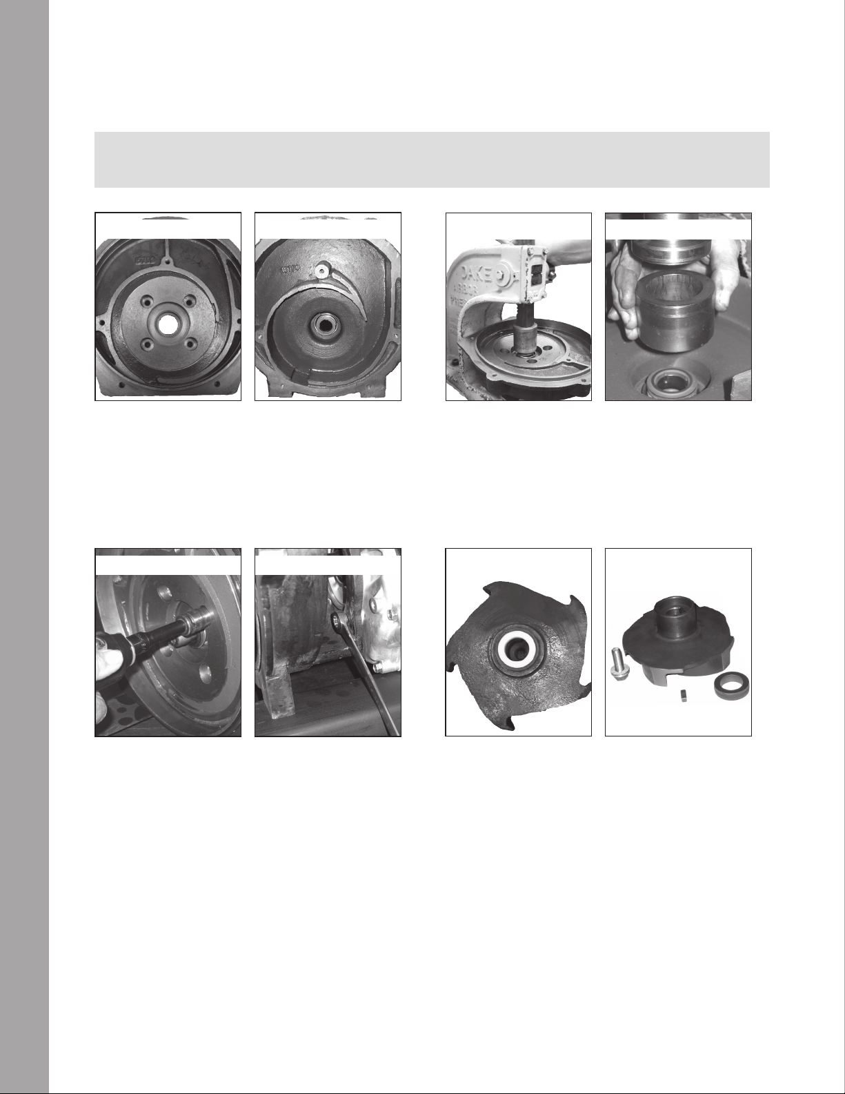
c. Verify that the impeller spacing is no more than 0.100″.
d. Verify that the impeller is secured to the engine shaft with a shaft key. This verication can be done by turning
the impeller (via the impeller bolt) on the pump by using a 5/8″ socket attached to a 6″ extension. If the impeller
turns without spinning drive unit impeller, the shaft key is broken or missing. Replace shaft key.
e. Verify that the customer does not have any kinks in the suction or discharge lines.
f. Verify that the pump inlet, outlet, suction line or discharge line is not (partially) blocked.
g. Verify all plumbing system valves are open.
6. ENGINE BOGS DOWN DURING PUMP OPERATION / ELECTRIC MOTOR TRIPS CIRCUIT BREAKER DURING
START UP OR OPERATION.
a. Verify that the customer does not have any kinks in the suction or discharge lines.
b. Verify that the pump inlet, outlet, suction line or discharge line is not (partially) blocked.
c. Verify that the impeller spacing is no less than .080″. The impeller should not be touching the wear plate/volute.
d. Verify the weight of uid being transferred. Make sure that the drive unit is properly sized for the pump and its
application.
7. GRINDING, TICKING OR WHIRRING SOUND DURING PUMP OPERATION THAT IS UNUSUAL.
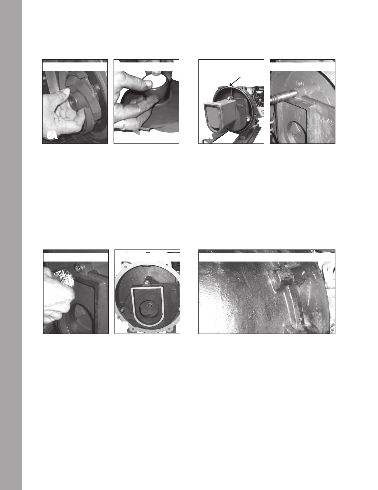
a. Verify that the impeller bolt has not loosened, letting the impeller pull itself into the volute. The impeller spacing
should be no less than .080″. The impeller should not be touching the wear plate/volute.
b. Verify that outside diameter is not hitting the pump housing or volute. Slowly rotate the pump several times by hand.
If you can feel the pump dragging on the housing or volute or hear a scraping sound, the impeller may be hitting the pump
body or volute. The impeller can be removed from the pump and led down or trimmed down slightly on a lathe.
c. Remove the pump housing and inspect for internal debris such as rocks, sticks or other foreign material stuck inside
of pump. With the pump housing and volute removed, you can then inspect the impeller face and outside diameter for
signs of contact between the impeller and other pump components.
8. PUMP/ENGINE RUNS TEMPORARILY, THEN STOPS. THE PUMP/ENGINE WILL NOT RESTART.
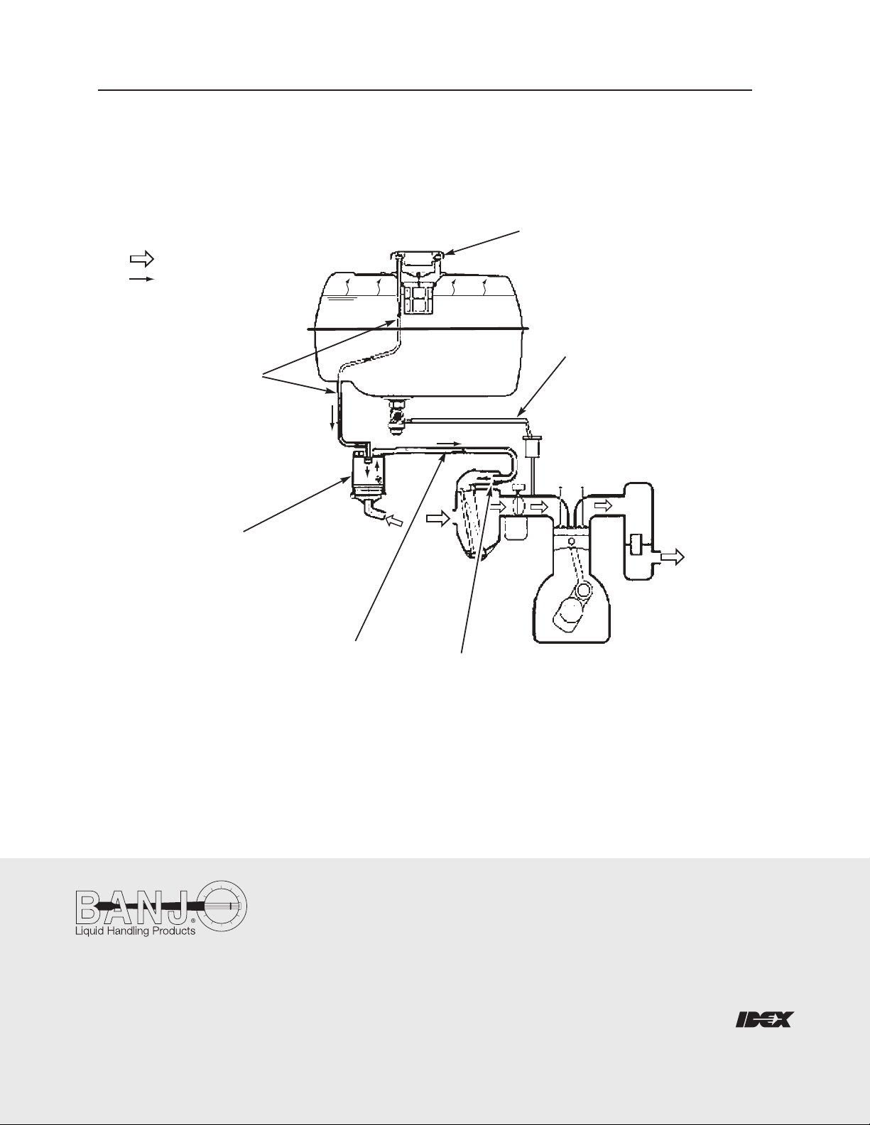
a. Verify that there is no external damage to the engine.
b. Verify that engine has the manufacturer’s recommended amount and grade of oil in the engine.
c. Verify that the engine gas tank has been lled with a minimum of 87 octane unleaded gasoline. Verify that the
gasoline is fresh and clean.
d. Verify that the spark plug wires are properly connected to the spark plugs.
e. Verify that the impeller bolt has not loosened, letting the impeller pull itself into the volute. The impeller spacing
should be no less than .080″. The impeller should not be touching the wear plate/volute.