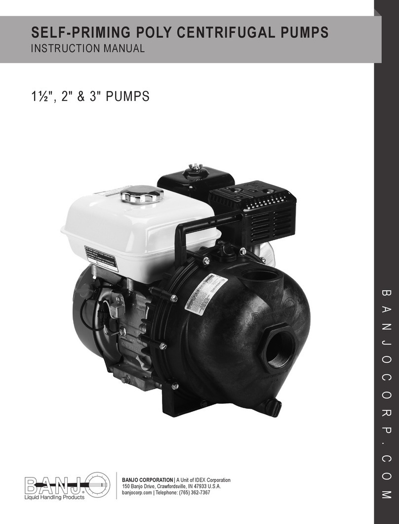
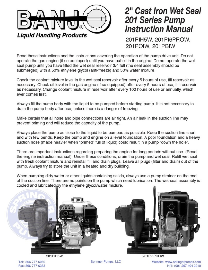
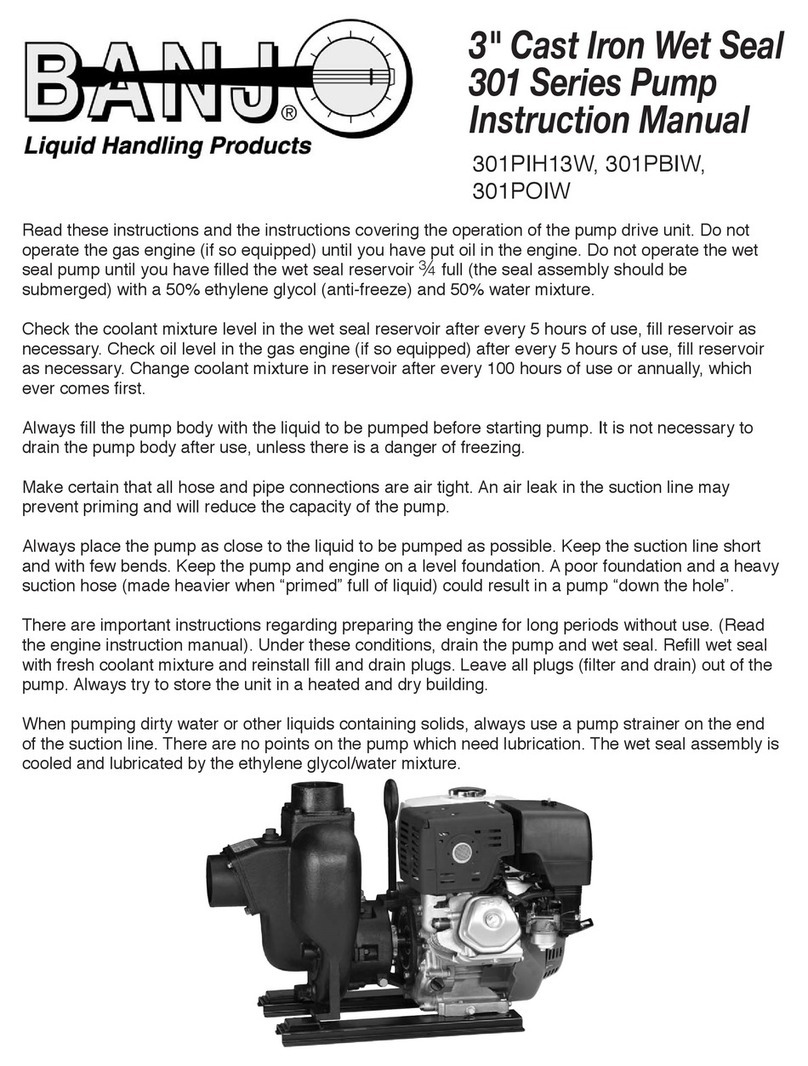
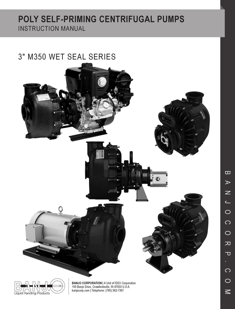
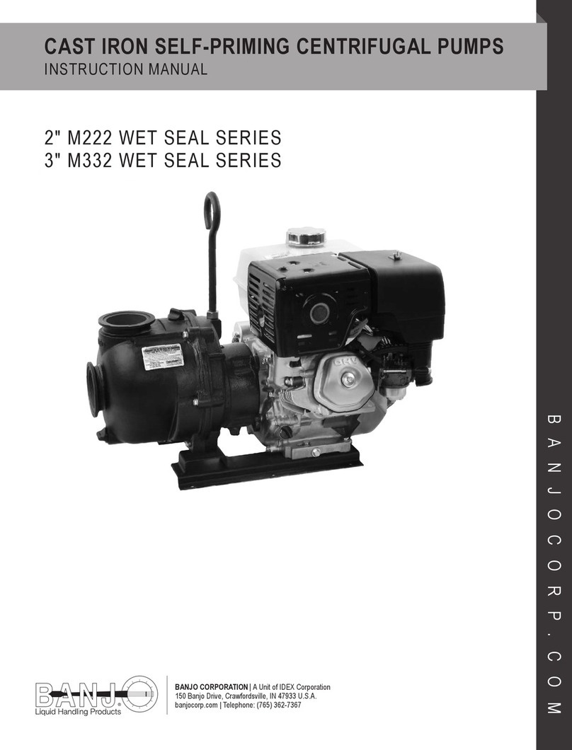
Banjo M350 Series User manual

POLY SELF-PRIMING CENTRIFUGAL PUMPS
INSTRUCTION MANUAL
BANJO CORPORATION | A Unit of IDEX Corporation
150 Banjo Drive, Crawfordsville, IN 47933 U.S.A.
banjocorp.com | Telephone: (765) 362-7367
BANJOCORP.COM
3″ M350 WET SEAL SERIES

CONNECT WITH CONFIDENCE™2
OPERATION WARNING
Do not operate the gas engine (if equipped) until you
have put oil in the engine. This pump is designed to
tolerate incidental dry running without damage but
do not intentionally run the pump dry.
WARNING! DO NOT USE WITH
FLAMMABLE LIQUIDS.
Do not use ammable liquids. This pump is not
designed or produced to pump ammable liquids of
any kind. Failure to follow this warning can result in
explosion, serious bodily injury or death.
OVERVIEW
Read these instructions and the instructions covering operation of the pump drive unit.
The gas engine (if equipped) is shipped with no oil. Consult your owners manual for specic oil recommendations, maintenance
procedures, schedules, and troubleshooting. The maximum angle of operation for gas engine drive units is 25° in all directions. For
engine warranty service, contact your local engine dealer.
Make certain that all hose and pipe connections are airtight. An air leak in the suction line may prevent priming and will reduce the
performance of the pump.
Do not restrict the pump inlet. High volume pumps such as the Banjo M350 Series pumps should not have the inlet port or line
restricted. The pump should be plumbed with a 3" suction line. A 4" suction line may be used for better performance. Failure to follow
these instructions can result in pump cavitation and pump failure.
Always place the pump as close to the liquid to be pumped as possible. Keep the suction line short and with few bends. Keep the
pump and engine on a level foundation. A poor foundation and a heavy suction hose (made heavier when ″primed″ full of liquid) could
result in a pump ″down the hole″. It is not necessary to drain the pump body after use, unless there is a danger of freezing.
Antifreeze is needed to keep the pump seal cooled and lubricated. Check the coolant every 8 hours of use or when the gas tank is
lled if so equipped. Change the antifreeze every 500 hours or annually. When pumping dirty water or liquids containing solids, always
use a basket strainer on the end of the suction line.
Engine warranty service available at authorized Honda® & Briggs and Stratton® Dealers.
*Note: Do NOT operate pump without the supplied EPA approved fuel tank and lines.
WARNINGS
STORAGE WARNING
There are important instructions regarding the
preparation of the engine for long periods
without use (reference the engine owners manual).
Before long periods of storage, the pump should
be ushed with clean water and drained. Leave all
plugs (ll and drain) out of the pump. Always store
the pump in a heated and dry building.

CONNECT WITH CONFIDENCE™3
3″ POLYPROPYLENE PUMPS
Port Size
Suction............................3″ MANIFOLD
Discharge .......................3″ MANIFOLD
PERFORMANCE
M350 STANDARD CURVE FOR MODELS:
M350PE15W, M350PHAW, AND M350PBW
M350PVAN14W

CONNECT WITH CONFIDENCE™4
DISASSEMBLY INSTRUCTIONS:
Empty wet seal reservoir.
Remove clamp guards on the pump.
2A1
3 4
Remove the clamp from the shaft.
5
Remove bolts and lock washers on the back of the wet seal
reservoir.
Remove the key from the shaft.
65
2A Insert spacer tool.
2B Loosen the clamp.
Remove the pump from the engine.
2B

CONNECT WITH CONFIDENCE™5
Remove body bolts, lock washers, and nuts.
7
Remove spacer on the engine (Briggs & Stratton Vanguard®model
only).
9
Remove body from the rear bracket assembly.
8
Remove the body O-ring from the groove on the rear bracket.
10
11
Remove check valve from diffuser. Remove screws and diffuser.
12
DISASSEMBLY INSTRUCTIONS:

CONNECT WITH CONFIDENCE™6
DISASSEMBLY INSTRUCTIONS:
Remove the impeller from the shaft. If the impeller is stuck on the
shaft, a 7/16-14 bolt may be screwed into the impeller bolt hole to
remove the impeller.
13
Remove impeller bolt.
15
Remove hex nut and key from the impeller.
14
Remove the seal spring and retainer.
16
17
Remove bolts from the back of the reservoir. Remove the reservoir assembly from the rear bracket. The rotating
half of the seal can now be removed from the shaft.
18

CONNECT WITH CONFIDENCE™7
Remove seal and shaft from reservoir and separate seal from shaft.
Remove lock washers and nuts from grooves in rear bracket.
Remove O-ring from the groove on the back of the rear bracket.
20
21
19
22
Remove the yellow spacer on back side of reservoir.
Remove the 2 ceramic seals from the reservoir and rear bracket. A
wide at bladed screwdriver may be used to carefully pry the seals
out. Use caution when applying pressure as the ceramic seals are
fragile and may crack. Set aside the seals.
23
DISASSEMBLY INSTRUCTIONS:

CONNECT WITH CONFIDENCE™8
ASSEMBLY INSTRUCTIONS:
TOOLS REQUIRED:
9/16", ½″ Box End Wrench, 9/16", ½" Socket, Ratchet with 6″ Extension,
Locktite 242 and P80 lubricant
3A Apply P80 lube to the inside of the seal and install it onto the
shaft.
3B Push shaft assembly into reservoir keeping the keyway facing to
the top of the rear bracket.
Install the 2 ceramic seals into the reservoir and rear bracket. A at
uniform object and rubber mallet can be used to install the ceramic
seal. Use caution when applying pressure as the ceramic seals are
fragile and may crack.
Clean the new seals thoroughly and lubricate with P80 lubricant.
21
4
Press down on the shaft and insert the yellow spacer on back side
of reservoir into the top slot on the shaft. *
Install lock washers and nuts into grooves in rear bracket.
56
Lubricate the O-ring with P80 and install O-ring into the groove on
the back of the rear bracket.
* If the spacer tool is dislodged:
Before step 13: The impeller may be pushed down so the spacer tool can be re-installed.
After step 13: A ½" socket on a 6" extension may be used to push the impeller bolt down so the spacer tool can be re-installed.
3A 3B

CONNECT WITH CONFIDENCE™9
ASSEMBLY INSTRUCTIONS:
Install bolts into the back of the reservoir and tighten into the rear
bracket.
7
With the part number text on the rear bracket facing right side up,
place the reservoir assembly onto the rear bracket with the shaft
oriented downward and the handle facing away from you.
9
Lubricate inside of seal and outside of the shaft with P-80 and press
the seal onto the shaft.
8
Install hex nut and key into the impeller. A dab of grease may be
used to hold them in place during assembly, if necessary.
10
11
Align the key in the impeller with the keyway on the shaft and press
the impeller onto the shaft.
Install and tighten impeller bolt.
12

CONNECT WITH CONFIDENCE™10
ASSEMBLY INSTRUCTIONS:
Install check valve onto diffuser.
13
Install diffuser and tighten screws.
15
Place the body O-ring into the groove on the rear bracket.
14
Place body onto the rear bracket assembly ensuring the check
valve groove is aligned correctly. If pump body is fully seated, body
bolts will drop into place without resistance.
16
17
Insert and tighten body bolts, lock washers, and nuts. Place spacer on the engine for gas models.
18

CONNECT WITH CONFIDENCE™11
ASSEMBLY INSTRUCTIONS:
Attach clamp to the shaft of the pump but do not tighten beyond
nger-tight.
19
Rotate the shaft so the keyway faces up and insert the key into the
keyway on the shaft.
21
Slide the pump onto the engine ensuring the key on the shaft lines
up with the keyway on the pump.
20
Insert bolts and lock washers through the bolt holes on the back of
the wet seal reservoir and into the engine and tighten.
22
23A Torque the clamp to 38-42 ft lbs.
23B Pull spacer tool out and ensure the pump turns freely.
Attach clamp guards to the pump and screw into place.
Fill wet seal reservoir with 50/50 mix of antifreeze and water.
24
23A 23B

CONNECT WITH CONFIDENCE™12
TROUBLESHOOTING GUIDE:
1. GAS ENGINE WILL NOT START.
a. Verify that there is no external damage to the engine.
b. Verify that engine has the manufacturer’s recommended amount and grade of oil in the engine.
c. Verify that the engine gas tank has been lled with a minimum of 87 octane unleaded gasoline. Verify that the
gasoline is fresh and clean.
d. Verify that the spark plug wires are properly connected to the spark plugs.
e. Verify that the battery cables are tight and properly connected to both the battery and engine.
f. Verify that the battery is fully charged and in good condition.
g. Review starting procedures and/or trouble-shooting guide in engine owners manual.
h. Contact the engine manufacturer for warranty assistance and repair information.
Honda®: 800-426-7701 | www.honda.com
Briggs and Stratton®:414-259-5262 | www.briggsandstratton.com
2. PUMP WILL NOT PRIME.
a. Verify that the pump is lled with uid prior to start up via the ll hole located on the top of the pump.
b. Verify that the uid is not being lifted more than 25 vertical feet.
c. Verify that there are no kinks in the suction line.
d. Verify that the pump inlet or suction line is not clogged.
e. Verify that the suction line does not have any vacuum leaks at any of the connections.
f. Verify that the pump is operating at a minimum of 3450 RPM for lifting and self-priming applications. Banjo pump will
not prime while operating below 1750 RPM.
g. Verify correct pump rotation if an electric motor or hydraulic motor is being used. A counter clockwise rotation
(right hand rotation) is required from the motor.
3. PUMP LOOSES PRIME DURING OPERATION.
a. See 2B above.
b. See 2C above.
c. Verify that the pump inlet or suction line is not clogged.
d. Verify that the suction line does not have any vacuum leaks at any of the connections.
e. Verify that the pump is operating at a minimum of 3450 RPM for lifting and self-priming applications.
Banjo pump will not prime while operating below 1750 RPM.
4. ENGINE RUNS BUT PUMP DOES NOT TRANSFER LIQUID.
a. Verify that the pump is operating at a minimum of 1750 RPM. Banjo pumps may not operate below this RPM.
b. Verify correct pump rotation if an electric motor or hydraulic motor is being used. A counter clockwise rotation
(right hand rotation) is required from the motor.
c. Verify that the impeller is secured to the engine shaft with a shaft key, the adapter shaft is secured to the engine shaft with a
shaft key, and the shaft clamp is tight. This verication can be done by turning the impeller (via the impeller bolt) by using a ½″
socket attached to a 6″ extension. If the impeller turns without spinning the drive unit, replace shaft keys and tighten shaft clamp,
making sure to use the spacer tool for proper impeller-diffuser spacing.
d. Verify that the customer does not have any kinks in the suction or discharge lines.
e. Verify that the pump inlet, outlet, suction line, or discharge line is not (partially) blocked.
f. Verify all plumbing system valves are open.
(Continued on next page)

© Copyright 2022 Banjo Corporation. All Rights Reserved.
BANJO_MAN_KK-108_M350_Poly_WetSeal_PumpManual_Rev1122
BANJO CORPORATION
A Unit of IDEX Corporation
150 Banjo Drive
Crawfordsville, IN 47933 U.S.A.
Telephone: (765) 362-7367
Tech Sales: (888) 705-7020
Fax: (765) 362-0744
banjocorp.com
#yellowhandle
Please see banjocorp.com for more information
5. MOTOR RUNS BUT PUMP DOES NOT PERFORM ADEQUATELY.
a. Verify that the pump is operating at a minimum of 1750 RPM. Banjo pumps may not operate below this RPM.
b. Verify correct pump rotation if an electric motor or hydraulic motor is being used. A counter clockwise rotation
(right hand rotation) is required from the motor.
c. Verify that the impeller is secured to the engine shaft with a shaft key, the adapter shaft is secured to the engine shaft with a
shaft key, and the shaft clamp is tight. This verication can be done by turning the impeller (via the impeller bolt) by using a ½″
socket attached to a 6″ extension. If the impeller turns without spinning the drive unit, replace shaft keys and tighten shaft clamp,
making sure to use the spacer tool for proper impeller-diffuser spacing.
d. Verify that the customer does not have any kinks in the suction or discharge lines.
e. Verify that the pump inlet, outlet, suction line, or discharge line is not (partially) blocked.
f. Verify all plumbing system valves are open.
6. ENGINE BOGS DOWN DURING PUMP OPERATION / ELECTRIC MOTOR TRIPS CIRCUIT BREAKER DURING
START UP OR OPERATION.
a. Verify that the customer does not have any kinks in the suction or discharge lines.
b. Verify that the pump inlet, outlet, suction line, or discharge line is not (partially) blocked.
c. Verify that the impeller is not touching the diffuser.
d. Verify the weight of uid being transferred. Make sure that the drive unit is properly sized for the pump and its
application.
7. GRINDING, TICKING OR WHIRRING SOUND DURING PUMP OPERATION THAT IS UNUSUAL.
a. Verify that the impeller bolt has not loosened, letting the impeller pull itself into the diffuser. The impeller should not be touching
the diffuser.
b. Verify that the impeller is not rubbing diffuser. Slowly rotate the pump several times by hand. If you can feel the pump dragging
or hear a scraping sound, the impeller may be rubbing the diffuser. If that is the case, inspect the impeller and diffuser for
damage, then re-assemble the pump using the spacer tool to set the proper impeller-diffuser gap.
c. Remove the pump housing and inspect for internal debris such as rocks, sticks, or other foreign material stuck inside
of pump.
8. PUMP/ENGINE RUNS TEMPORARILY, THEN STOPS. THE PUMP/ENGINE WILL NOT RESTART.
a. Verify that there is no external damage to the engine.
b. Verify that engine has the manufacturer’s recommended amount and grade of oil in the engine.
c. Verify that the engine gas tank has been lled with a minimum of 87 octane unleaded gasoline. Verify that the
gasoline is fresh and clean.
d. Verify that the spark plug wires are properly connected to the spark plugs.
e. Verify that the impeller bolt has not loosened, letting the impeller pull itself into the diffuser. The impeller should not be touching
the diffuser.
This manual suits for next models
1
Table of contents
Other Banjo Water Pump manuals
Popular Water Pump manuals by other brands

Grundfos
Grundfos TPE 2000 Series Installation and operating instructions

IWAKI PUMPS
IWAKI PUMPS AMP Series instruction manual

Standart
Standart PC-V Series Instructions for installation, operation, maintenance

SFA
SFA Sanifloor+ Operating & installation manual

Salamander Pumps
Salamander Pumps CT Force installation guide

Grundfos
Grundfos SP Installation and operating instructions