banks Power Stinger User manual

09/25/18 PN 96824 v.4.0
Banks Power Pack®
/Stinger®System
Compatible with Optional Banks iQ™
2003-2007 Ford Power Stroke 6.0L
Turbo-Diesel Pickups
THIS MANUAL IS FOR USE WITH SYSTEM 63743, 63745, 63747 & 63748
For iDash 1.8 instructions, see iDash 1.8 manual 97654
Gale Banks Engineering
546 Duggan Avenue • Azusa, CA 91702
(626) 969-9600 • Fax (626) 334-1743
Product Information & Sales: (888) 635-4565
Customer Support: (888) 839-5600
Installation Support: (888) 839-2700
bankspower.com
©2018 Gale Banks Engineering
Owner’sManual
with Installation Instructions

Banks iQ System
(P/N 61151-61152)
- 5” touchscreen interface that
can control the Banks Diesel
Tuner and/or SpeedBrake on
the fly.
- Interchangable gauge display,
read and clear codes, monitor
engine diagnostics, log data,
time your vehicles runs and
much more.
Banks Monster®Exhaust
System
Sport (P/N 48790-48793)
Single and Dual (P/N 47285-
47292, 47606-47609, 48783-
48788)
- Increases exhaust flow, cuts
backpressure, lowers exhaust
gas temperatures (EGTs) and
increases power.
Banks Ram-Air Intake System
(P/N 42155)
- Increases your airflow over
stock.
- Adds power, improves fuel
economy, lowers EGTs and
reduces smoke.
High-Ram Intake
(P/N 42750-42751)
- Increases flow and provides
more uniform air distribution
to the engine for more
available power at a given
boost level.
Banks Techni-Cooler®System
(P/N 25974-25975)
- Provides increased air flow to
the engine by increasing air
density for more increased
power, lower EGTs and
improved fuel economy.
Banks Brake
(P/N 55467-55468)
- Increases the stopping power
of your truck and extends the
service life of your brakes
Banks Billet Torque Converter
(P/N 72522)
- Higher torque capacity over
stock
- Lockup clutch is slip-resistant
so transmission fluids stay
cooler and transmission life is
prolonged.
Banks SpeedBrake
iQ Compatible (P/N 55455-
55456)
PDA Compatible (P/N 55457-
55458)
- Allows for controlled hill
decent at a user defined
vehicle speed.
Also Available from Banks Power
03-07 Ford 6.0L
296824 v.4.0

For More Information please call (800) 438-7693
or Visit us online @ www.bankspower.com
Boost and Pyro Gauges
(P/N 64507)
- Keep your engine safe by
monitoring vital engine
parameters
Banks Bullet
(P/N 66524-66525)
- Adds power safely to your
vehicle
- Displays critical engine
functions
- Engine safeguards
- Change power levels on-the-
fly
Banks Diesel Tuner
Six-Gun w/ switch (P/N 61023)
Six-Gun w/ iQ (P/N 63749)
EconoMind w/ switch (P/N
63743-63745)
EconoMind w/ iQ (P/N 63747-
63748)
- Adds power safely to your
vehicle
- Engine and transmission safe
guards
- Change power levels on-the-fly
Banks Speed-Loader
(P/N 62988)
- Furthers the power output of
the Banks Six-Gun and provides
EGT limiting safety.
Thermocouple
- Add a temperature limiting
function to your Diesel Tuner
OttoMind Programmer
(P/N 66064)
- Contains Banks tunes that
boost your vehicles HP, Torque
and MPG.
- Displays a host of critical
engine functions
- Provides “service technician”
diagnostic capabilities
- Has upgradeable functionality,
so it will never be out of date
Banks Stinger Systems
(P/N 46465-46486)
Contains:
- Ram-Air Intake system
- Monster Exhaust (single or
dual)
- EconoMind Tuner w/ Banks iQ
Banks PowerPack Systems
(P/N 46497-46519)
Contains:
- Ram-Air Intake system
- Monster Exhaust (single or
dual)
- EconoMind Tuner w/ Banks iQ
- High-Ram
- Techni-Cooler System
Banks Six-Gun Bundle
(P/N 46594-46613)
Contains:
- Ram-Air Intake system
- Monster Exhaust (single or
dual)
- Six-Gun Tuner w/ Banks iQ
Banks Big Hoss Bundle
(P/N 46623-46643)
Contains:
- Ram-Air Intake system
- Monster Exhaust (single or
dual)
- Six-Gun Tuner w/ Banks iQ
- Big Head Wastegate Actuator
- High-Ram
- Techni-Cooler System
96824 v.4.0 3

496824 v.4.0
Dear Customer, If you have
any questions concerning
the installation of your Banks
EconoMind Diesel Tuner,
please call our Technical
Service Hotline at (888) 839-
2700 between 7:00 am and
5:00 pm (PT). If you have any
questions relating to shipping
or billing, please contact our
Customer Service Department
at (888) 839-5600.
Thank you.
1. For ease of installation of your
Banks system, familiarize yourself
with the procedure by reading the
entire manual before starting work.
This manual contains 42 pages of
copy, illustrations and parts listing.
If any pages are missing from this
manual please call Gale Banks
Engineering immediately for a
replacement.
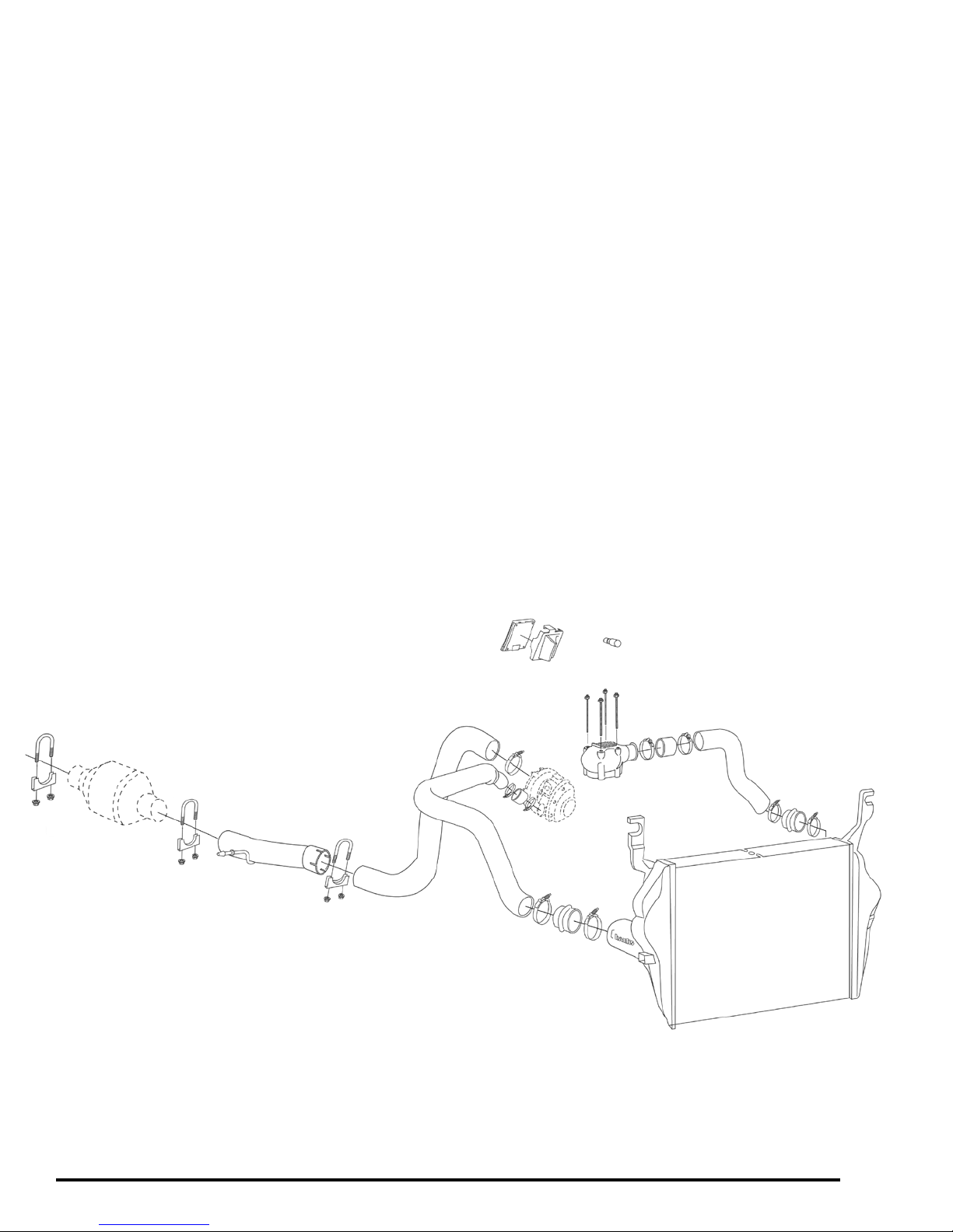
2. The exploded illustrations provide
only general guidance. Refer to each
step and section diagram in this
manual for proper instruction.
3. Throughout this manual, the
left side of the vehicle refers to the
driver’s side, and the right-side to the
passenger’s side.
4. Disconnect the ground cable from
the battery before beginning work. If
there are two batteries, disconnect
both.
5. Route and tie wires and hoses
a minimum of 6 inches away from
exhaust heat, moving parts and sharp
edges. Clearance of 8 inches or more
is recommended where possible.
6. During installation, keep the
work area clean. If foreign debris
is transferred to any Banks system
component, clean it thoroughly
before installing.
7. When raising the vehicle, support
it on properly weight-rated safety
stands, ramps or a commercial hoist.
Follow the manufacturer’s safety
precautions. Take care to balance
the vehicle to prevent it from slipping
or falling. When using ramps, be
sure the front wheels are centered
squarely on the topsides; put the
transmission in park; set the parking
brake; and place blocks behind the
rear wheels.
Caution! Do not use floor jacks
to support the vehicle while
working under it. Do not raise
the vehicle onto concrete
blocks, masonry or any other
item not intended specifically
for this use.
Warning: Below 32oF (0oC)
or above 140oF (60oC), the
Banks iQ may be susceptible
to damage as a result of
extended direct exposure to
sunlight, heat or extreme cold.
It is highly recommended that
Banks iQ be removed from
its mounting location if the
vehicle will be subjected to high
concentrations of sunlight, heat
or cold for an extended period
of time. Gale Banks Engineering
is not responsible for damage
to Banks iQ resulting from
exposure conditions.
General Installation Practices

96824 v.4.0 5
Tools Required:
• 1⁄4” and 3⁄8” drive ratchets
• Inch and metric deep sockets
• Ratchet extension
• Metric combination or open-end
wrenches
• Phillips and flat blade screwdrivers
• Standard and needle-nose pliers
• Pocket or X-Acto knife
• Clean shop towels or rags
• Drill bit set
• Drill motor
• Tap Handle
• 1⁄4” NPT tap
• 5⁄16 nut driver
• Pliers
• Torx bits
• Pry-bar
Highly recommended tools and
supplies:
• Multimeter or 12-volt test light
• Heat gun
• Foot-pound torque wrench
• Penetrating oil or light lubricant
spray
• Reciprocating saw
• Inch-pound torque wrench
Table of Contents
General Installation Practices ....4
Banks Powerpack System
Section 1 ......................8
Installation of Banks Monster Exhaust
System
Section 2 .....................16
Techni-Cooler Assembly Installation
Section 3 .....................23
Thermocouple Installation
Section 4 .....................24
Banks EconoMind Diesel Tuner
Installation
Section 5 .....................29
Mounting and Connecting the Banks iQ
Section 6 .....................32
Installation of the Power Level Selector
Switch
Section 7 .....................34
OPTIONAL Gauge Cluster Installation
Section 8 .....................35
Automatic Transmission Learning
Section 9 .....................35
Troubleshooting, EconoMind
Section 10 ....................38
Removal of the EconoMind Diesel Tuner
Section 11 ....................38
Placement of the Banks Power Decal

696824 v.4.0
General Assembly Diagram
BANKS POWERPACK SYSTEM

96824 v.4.0 7

896824 v.4.0
Section 1
INSTALLATION OF BANKS MONSTER EXHAUST SYSTEM
Figure 1a
General Assembly
Banks Monster Exhaust (Single Tailpipe)
2
8
3
9
94
Description Part # Qty.
1 Banks Monster Muffler 53800 1
2 Turbine Outlet Pipe
2003 (T.O.P.) w/ Resonator 53525 1
2004-2007 (T.O.P.) w/o Resonator 53537 1
3 Front Intermediate Pipe 53526 1
4 Rear Intermediate Pipe
Crew-Cab Long-bed / Crew-Cab Short-Bed) 53529 1
Rear Intermediate Pipe (Extended-Cab Long-Bed) 53530 1
Rear Intermediate Pipe (Extended-Cab Short-Bed) 53528 1
Rear Intermediate Pipe (Regular-Cab Long-Bed) 53527 1
Rear Intermediate Pipe (Excursion) 53534 1
5 Extension Pipe (Crew-Cab Long-Bed) 53531 1
6 Monster Tailpipe
(Truck) 53512 1
(Excursion) 53536 1
7 Polished 5” Exhaust Tip 52383 1
8 Exhaust Clamp, 4” (Crew-Cab Long-Bed contains 2 clamps) 52470 1
9 Exhaust Clamp, 31⁄2” 52468 2
10 Hanger Clamp, Front, Muffler
(Truck) 53453 1
(Excursion) 53498 1
11 Hanger Clamp, Rear, Muffler
(Truck) 53454 1
(Excursion) 53499 1
12 Hanger Pin Assembly (Crew-Cab Short-Bed) 53532 1
13 Spacers, 8mm (Long-Bed) 91019 2
14 Bolt, 8-1.25x30mm (Crew-Cab Short-Bed) 91788 2
15 Washer, Flat, 5⁄16”(Crew-Cab Short-Bed) 91202 2
16 Nut, Lock, 8-1.25mm (Crew-Cab Short-Bed) 91803 2

96824 v.4.0 9
85
12
16
10
15
14 13
1
11 6
7

10 96824 v.4.0
Figure 1b
General Assembly
Banks Monster Exhaust, Split-Dual
2
8
39
9
4
10
11
5
9
6
7
13
16
14
9
8
1
8
17
12
15
Description Part # Qty.
1 Banks Monster Muffler 53800 1
2 Turbine Outlet Pipe (T.O.P.)
2003 w/ Resonator 53525 1
2004-07 w/o Resonator 53537 1
3 Front Intermediate Pipe 53526 1
4 Rear Intermediate Pipe
(Crew-Cab Short-Bed) 53557 1
(Extended-Cab Long-Bed) 53558 1
(Extended-Cab Short-Bed) 53556 1
(Crew-Cab Long-bed) 53559 1
5 Y-Pipe
2003-2007 53574 1
6 Monster Tailpipe Pass. Side,
2003-2007 53575 1
7 Monster Tailpipe Drvr. Side,
2003-2007 53576 1
8 Exhaust Clamp, 4” 52476 2
9 Exhaust Clamp, 31⁄2” 52468 4
10 Hanger Clamp, Front, Muffler 53453 1
11 Hanger Clamp, Rear, Muffler 53455 1
12 Frame Hanger Bracket 53566 1
13 Rubber Insulator 53732 1
14 Nut, Nylock, 7⁄16-20 91617 2
15 Washer, SAE, 7⁄16” 91603 4
16 Bolt, 7⁄16-20 x 1 91627 2
17 Cable Tie, Black 5” 62001 3

96824 v.4.0 11

12 96824 v.4.0
Exhaust System Installation
Use the Bill of Materials Chart and
Figure 1a or 1b reference component
nomenclature and location. Use
caution when working in the engine
compartment. Make sure the engine
has been off for several hours and is
cool.
1. Disconnect the battery ground
cables from each of the batteries.
Secure the cables so that they do
not come in contact with the battery
posts.
2. Remove the (+) battery cable from
the driver side battery.
3. Remove the driver side plastic
battery cover. This is accomplished by
depressing a tab at the front and rear
of the cover. Be careful not to damage
the cover, as it will be re-installed.
4. Remove the driver side battery hold
down clamp (8mm socket).
5. Remove the driver side battery.
WARNING: When lifting a battery,
excessive pressure on the end
walls could cause acid to spew
through the vent caps, resulting
in personal injury. Lift with a
battery carrier or with hands
on opposite corners. Failure to
follow these instructions may
result in personal injury.
6. Raise the vehicle and support it
securely with properly weight-rated
safety stands, ramps or a commercial
hoist. Take care to balance the vehicle
to prevent it from slipping or falling.
When using ramps, be sure the wheels
are centered squarely on the topsides.
Place the transmission in park
(automatic) or reverse (manual), set
the parking brake and securely block
the wheels that are on the ground.
CAUTION: DO NOT WORK UNDER
ANY VEHICLE SUPPORTED ONLY
BY A JACK. SEVERE INJURY MAY
RESULT.
WARNING! The following step
may require the use of a torch
and/ or saw. Proper safety
equipment should be used.
Failure to use proper safety
equipment may result in severe
injury.
7. From under the vehicle remove
the factory exhaust system from the
catalytic converter back. Starting
at the rear of the vehicle, remove
each component by either cutting
through the pipe near the clamps or
by removing the clamps and heating
the joints with an oxyacetylene torch
to allow crimped pipes to separate.
DO NOT CUT OR DAMAGE CATALYTIC
CONVERTER TUBING DURING THE
REMOVAL PROCESS. To assist in
removal, the T.O.P. should be cut
before the transmission if it is going to
be replaced. Remove the hanger pins
from the rubber hangers with a pry
bar. (Spray lubricant will ease hanger
removal.)
8. Remove the two (2) nuts attaching
the turbine outlet pipe (T.O.P.) to the
catalytic converter inlet. Loosen and
remove the band clamp that attaches
the rear intermediate pipe to the
catalytic converter outlet. Remove
the catalytic converter assembly
from the vehicle. Remove the v-band-
clamp that attaches the T.O.P. to the
turbocharger and remove the factory
T.O.P. from the vehicle. Retain V-band
clamp for re-assembly.
Note: To assist in T.O.P. removal,
remove the rear engine hoist hook
by removing the two (2) Hex screws
and remove the valve cover heat
shield. The dipstick tube may also be
removed or slightly bent to allow for
T.O.P. removal/installation. Retain all
hardware and parts for reassembly.
9. For Manual Transmissions
only: The transmission will need
to be lowered to allow for removal
and installation of the T.O.P. Using a
Transmission Jack, support the rear
of the transmission to allow working
room for the T.O.P. and remove the
rear transmission mount and cross
member. Remove the Front drive shaft
support bracket from the cab. Lower
the transmission 4-6” and remove
the factory T.O.P. The transmission
may need to be raised before the
Banks T.O.P. is installed. Install the
Banks T.O.P. Raise the transmission
and reinstall drive shaft bracket,
transmission cross member and rear
transmission mount. Refer to vehicles
owners manual for factory Torque
Specifications.
10. Loosely place the factory V-band
clamp on the Banks T.O.P. Install the
Banks T.O.P. to the turbine housing.
Loosely snug the V-band clamp
assuring the T.O.P. is aligned properly.
Note: Reinstall the engine hoist
hook and valve cover heat shield if
previously removed.
11. The catalytic converter inlet will
need to be trimmed to accommodate
the Banks exhaust system. Be careful
not to trim an excessive amount of
tubing. Be sure to wear proper safety
equipment.
IMPORTANT: Diesel catalysts
may become plugged with soot,
which can restrict exhaust flow,
impeding performance. Inspect
the converter by shining a
powerful flashlight into the inlet.
Observe the light through the
other end of the converter. The
full circle of the flashlight should
be visible without any blockage
in the grid work of the catalyst.
If excessive soot is observed,
the catalyst may need to be
cleaned. TAKE PRECAUTIONS to
avoid blowing soot toward the
work area or where it could be
inhaled. ALWAYS use breathing
protection. Also inspect the
catalyst for damage (i.e. chips,
bent corners, etc.) to the grid
work. If your catalytic converter
is damaged, it may be covered
under your vehicle’s emissions
warranty.
12. With the catalytic converter
removed from the vehicle and the
head pipe removed from the converter,
measure approximately 4” from the
weld and mark the location (this
location should be before any bend,
about 7” rear of the inlet flange). Using
a reciprocating saw or equivalent,
vertically cut and remove 7” from the
converter inlet tubing. Make sure cut is
square (see Figure 2).
13. Install the supplied Banks front
intermediate pipe onto the previously
installed Banks T.O.P. Loosely install
a supplied 4” exhaust clamp onto the
forward end of the front intermediate
pipe.
14. Install the supplied 31⁄2”
clamp onto the outlet of the front
intermediate pipe. Place the trimmed
catalytic converter onto the previously
installed front intermediate pipe. Be
sure the notch and catalytic converter
pin are properly aligned. Snug the
clamp onto the catalytic converter
inlet, but do not tighten at this time.
15. Place a supplied 31⁄2” clamp
onto the front of the supplied rear
intermediate pipe.
16. Install the supplied rear
intermediate pipe onto the catalytic
converter outlet. Lightly snug the
31⁄2” clamp onto the front of the
intermediate pipe / catalytic converter
outlet.

96824 v.4.0 13
Note: Exhaust clamps should be
placed at the beginning of the slot
and evenly tightened.
Step 17 thru 26 applies only to
single tailpipe systems.
Skip to Step 27 thru 36 if installing
Banks-Dual Monster Exhaust System.
Single Tailpipe System (Step 17 thru
27)
17. Crew-cab long-bed model
only, Install the supplied extension
pipe onto the intermediate pipe and
snug a supplied 4” clamp onto the
connection.
18. Relocate the factory-installed
frame-mounted hanger pin that is
located behind the rear transmission
cross member.
19. Remove the two (2) factory nuts
that mount the front muffler hanger
pin to the frame rail and remove the
hanger pin from the vehicle.
Note: Extended cab short bed models
will NOT use the two (2) 3⁄8” spacers.
20. Re-install the frame mounted
hanger pin using the two (2) 3⁄8”
long steel spacers onto the factory
exhaust hanger studs. Install the
hanger/spacer assembly into the
vehicle frame holes about 10-16” to
the rear of the original muffler hanger
location (see Figure 3).
Note: spacers are to be installed
between the hanger pin and the
inside of the frame rail. Torque
factory nuts to 20 ft-lbs.
21. Using a pry bar, completely
remove the rubber hanger from the
front muffler hanger pin.
22. Reinstall the rubber hanger onto
the mounted hanger pin assembly.
23. Install the single pin front
hanger clamp onto the rear of the
intermediate pipe with the hanger pin
on the inside facing the muffler. Insert
the hanger pin into the vehicle’s
rubber grommet. Install the inlet of
the Banks Monster muffler to the
intermediate pipe.
24. Install the dual pin rear hanger
clamp onto the outlet of the Monster
muffler with the hanger pins on the
inside, facing the muffler.
25. Route the tailpipe over the rear
axle housing and into the muffler
outlet. Install the tailpipe hanger pin
into the corresponding rubber hanger.
Loosely snug the 4” hanger clamp
onto the muffler outlet.
26. Install the 5” Monster tailpipe tip
on the exhaust. Keep the wrapping
on until installation is complete. The
tip should be rotated so the clamp
nut and drain hole are pointing down.
Align the end of the tip with the
bodyline of the truck.
Proceed to Step 37.
Figure 2
Figure 3

14 96824 v.4.0
Banks Split-Dual Monster
Exhaust System (Step 27 thru 36)
27. For Long Bed models, install
the supplied hanger clamp onto the
intermediate pipe outlet. Insert the
hanger clamp pin into the vehicle’s
rubber grommet (see Figure 4).
28. For Short Bed models,Install
a 4” clamp on the inlet of the Banks
Monster muffler.
29. Install the Banks Monster Muffler
onto the intermediate pipe outlet and
lightly tighten the 4” clamp / hanger
clamp. Note inlet labeling stamped on
the bottom of the muffler. Orient the
Banks Monster emboss such that it is
level with the frame.
30. For Short Bed models, install
the supplied hanger clamp onto the
Monster Muffler outlet. Insert the
hanger clamp pin into the vehicle’s
rubber grommet (see Figure 4).
31. For Long Bed models, Install a
4” clamp on the outlet of the Banks
Monster muffler.
32. Install the Y-pipe into the
Monster Muffler outlet. Insert the two
y-pipe hanger pins into the vehicles
rubber grommets (see Figure 4).
33. Install the Banks rubber insulator
onto the supplied hanger bracket.
Locate the two slots on the rear driver
side frame and install the hanger
bracket assembly using the 7⁄16”
Hardware (see Figure 5).
34. Install two 31⁄2” clamps onto the
top and bottom of the Y-pipe. Route
the Driver side tailpipe over the axle
and insert into the upper Y-pipe.
Install the tailpipe hanger pin into the
rubber grommet.
35. Route the Passenger side tailpipe
over the axle and insert into the lower
Y-pipe. Install the tailpipe hanger pin
into the Banks rubber grommet.
36. Move the spare tire to the rear
of the vehicle. Adjust the tailpipe tips
to be 1⁄2” off the body panel and snug
the two 31⁄2” clamps. Move the spare
tire such that there is equal distance
for each tailpipe (see Figure 6).
DRIVERS SIDE
TAILPIPE
3 1/2”
CLAMP
3 1/2”
CLAMP
BANKS Y-PIPE
ORIENTATION
HANGER CLAMP
LOCATION FOR
SHORT BEDS
NOTE ORIENTATION
OF MONSTER MUFFLER
FORWARD
HANGER CLAMP
LOCATION FOR
LONG BEDS
PA SSENGER SIDE
TAILPIPE
Figure 4
FACTORY
LEAF STOP BANKS
HANGER
BRACKET
FACTORY
FRAME
SLOT
BANKS
RUBBER
INSULATOR
BANKS
7/16”
HARDWARE
BANKS
DRIVER SIDE
TAILPIPE
FORWARD
Figure 5

96824 v.4.0 15
ALL MODELS
37. With everything positioned
properly, begin to tighten the clamps
starting with the ones closest to the
front and working your way back.
Torque the exhaust clamps evenly
to 35 ft-lbs. Make sure that each slip
is fully inserted (+/-1⁄4inch) and that
all mount hangers are in the forward
position (see Figure 7). Torque 7⁄16”
hanger bracket hardware to 45 ft-lbs.
38. Remove the protective covering
from the tailpipe tip.
Caution: The protective covering
may ignite and burn if not
removed prior to running the
engine.
39. Tighten the exhaust clamps as
necessary. Whenever possible, tack-
welding slip connections to prevent
disengagement is recommended. The
Banks Monster Exhaust installation is
now complete.
-END, SECTION 1-
BANKS
DRIVER SIDE
TAILPIPE
ZIP TIE ON
VENT HOSE
& BRAKE LINE BANKS
PA SSENGER SIDE
TAILPIPE
ADJUST SO THAT
SPARE TIRE TO
TAILPIPE CLEARANCE
IS THE SAME MOVE SPARE
TIRE TOWARDS
REAR OF
VEHICLE
Figure 6
Figure 7

16 96824 v.4.0
Section 2
TECHNI-COOLER ASSEMBLY INSTALLATION
Figure 8
General Assembly
Banks Techni-Cooler Intercooler System
Item Description P/N Qty
1 Techni-Cooler Assembly 25536 1
2 Boost Tube, Left 41324 1
3 Boost Tube, Right 41325 1
4 Hose, 3.5”x 3.25”, Black 94215 1
5 Hose, 2.5”x 2.5”, 5-ply, Black 94273 1
6 Hump Hose, 3.5”x 3.25”, Black 94293 2
7 High-Ram Intake Manifold
2003-04 42745 1
2005-07 42746 1
8 Gasket, High-Ram Intake 93038 1
9 Stud, High-Ram Air Intake M6-1.0 x 1⁄4-20 x 4.365 (03-04) 91534 3
9 Stud, High-Ram Air Intake M6-1.0 x 1⁄4-20 x 6.185 (05-07) 91536 2
10 Stud, High-Ram Air Intake M6-1.0 x 1⁄4-20 x 6.725 (03-04) 91535 1
10 Stud, High-Ram Air Intake M6-1.0 x 1⁄4-20 x 6.595 (05-07) 91537 2
11 Nut, Nylock 1⁄4”-20 91110 4
12 Washer, SAE Flat, Zinc 1⁄4” 91102 4
13 Washer, Thread Sealing 1⁄4”-20 91106 2
14 O-Ring. High-Ram 93606 2
15 Spacer, Battery Box 91890 1
16 Hex-Bolt, Washer Head, Black 8mm-1.25 x 30mm 91810 2
17 Hose clamp, 3.5” Spring Loaded 92897 6
18 Hose clamp, 2.5” Spring Loaded — *
* These are stock components that will be re-used with the Banks Techni-Cooler System

96824 v.4.0 17
Note: If installing a Stinger System,
proceed to Section 3.
REMOVE STOCK COMPONENTS
Note: Save all factory components
and fasteners that are removed for
re-installation with the exception
of: Charge Air Cooler (CAC), Intake
Elbow, Boost Tubes, and CAC Hose
Connections.
1. Remove all of the plastic pushpins
that attach the upper radiator air
deflector to the grill support and
upper radiator support.
2. Remove the upper radiator air
deflector.
3. Place reference marks around the
hood latch to mark its location. These
marks will be used to orient the hood
latch upon re-installation.
4. Unbolt and remove the hood latch
from the support. Do not disconnect
the cable; just place the hood latch
assembly out of the way.
5. Remove the two upper a/c
condenser mounting brackets that are
attached to the upper radiator support
as shown in Figure 9.
6. Remove the 2 bolts that attach
the upper Charge Air Cooler (CAC)
mounts to the upper radiator support
as shown in Figure 10.
7. Remove the two radiator support
brackets as shown in Figure 11.
8. Remove the driver and passenger
side pushpins that attach the air
deflectors to the radiator support as
shown in Figure 12.
9. Un-clip the battery cable that is
attached to the radiator support.
10. Remove the 8 bolts that attach
the upper radiator support to the core
support.
11. Remove the radiator support. It
may be necessary to pry it out of the
slots in the core support.
12. Undo the two toggle clamps at
the rear of the air box assembly.
13. Disengage the two tabs on
the lower backside of the air box
assembly from the slots on the rear
cover.
14. Remove the air box assembly
and air box front cover from the
vehicle.
Figure 10
Figure 9
Figure 11

18 96824 v.4.0
15. For 2005-07 4-wheel drive
equipped vehicles only: Remove
the electronics module near the
driver side battery shown in Figure
13. The retaining tab for the module
can be pried back with a flat blade
screwdriver as shown in the Figure
13.
After the tab is depressed, the module
can easily be pulled away from it’s
mounting bracket.
Note: Be careful not to break the
plastic box, as it will be re-installed
later
16. Remove the wire harness plastic
retaining clip on the back of the
plastic battery box.
17. Remove the plastic battery box
[(4x) 13mm socket].
For 2005-07 4-wheel drive
equipped vehicles only: A small
bracket used to mount an electronic
module will also be removed with the
plastic battery tray.
18. Remove both the driver and
passenger side boost tubes and their
attachment hoses. The passenger
side boost tube is the 3-inch diameter
tube that connects the compressor
discharge to the charge air cooler.
The driver’s side boost tube connects
the charge air cooler to the intake
manifold. Retain the hose clamps
that attach the passenger side boost
tubes to the turbocharger, as these
components will be re-used.
19. Remove the four Allen head bolts
that attach the stock intake elbow.
The intake elbow is the 90-degree
transition from the driver side boost
tube to the intake manifold.
Figure 12
Figure 13

96824 v.4.0 19
20. Remove the stock intake elbow
and gasket.
21. Cover the compressor outlet on
the turbocharger and the inlet to the
intake manifold to prevent debris from
getting into either of these areas.
22. Remove the stock CAC.
MODIFICATIONS TO MAKE ROOM
FOR THE BANKS TECHNI-COOLER
SYSTEM
23. For 2005-07 4-wheel drive
equipped vehicles only:Remove
the two retaining clips that attach the
wire harness to the metal battery tray.
24. Remove the driver’s side metal
battery tray [(3x) 13mm socket].
25. Drill a 3⁄8inch hole as shown in
Figure 14.
26. Reinstall the battery tray as
shown in Figure 15 with the supplied
1⁄2” spacer and longer supplied 8mm
bolts. Torque the bolts to 12 ft-lbs.
Figure 15
Figure 14

20 96824 v.4.0
TRIM BRACKETS
2003 to 2004 vehicles only (Steps
27 through 33)
If installing on 2005-2007 vehicle
proceed to Step 34.
27. Remove the passenger side
battery hold down clamp [(1x) 8mm
socket].
28. Remove the passenger side
battery.
WARNING: When lifting a battery,
excessive pressure on the end
walls could cause acid to spew
through the vent caps, resulting
in personal injury. Lift with a
battery carrier or with hands
on opposite corners. Failure to
follow these instructions may
result in personal injury.
29. Remove the plastic clip that
attaches the (+) battery cable to the
rear of the passenger side battery tray
30. Remove the 4 bolts that secure
the passenger side battery tray [(4x)
13mm socket].
31. Remove the passenger side
battery tray.
32. Trim the bracket below the
battery tray as shown in Figure 16.
Note: Be careful not to cut the a/c
lines that are in close proximity to the
bracket.
33. Re-install the passenger side
battery tray and battery. Tighten the
battery tray bolts to 12 ft-lbs and the
battery hold down clamp to 89 in-lbs.
Re-attach the harness mounting clip
at the rear of the tray, but leave the
cables disconnected from the battery
until the installation is complete.
ALL VEHICLES
34. Trim the fan shroud as shown in
Figure 17 using Template 1 in Page
39 of this manual, to clear the larger
diameter boost tubes.
35. Trim the fan shroud as shown in
Figure 18 using Template 2 in Page
39 of this manual, to clear the Banks
High Ram.
Note: 2005-07 vehicles require a
different trim to fan shroud, use
appropriate template. See Template
2.
Figure 17
Figure 16
Figure 18
This manual suits for next models
1
Table of contents
Other banks Automobile Part manuals
Popular Automobile Part manuals by other brands

Metra Electronics
Metra Electronics 99-9501B installation instructions

Edelbrock
Edelbrock 5766 installation instructions

Elaflex
Elaflex ARK 19 Installation information

Edelbrock
Edelbrock Later Harley-Davidson 1604 installation instructions

ICON
ICON 98500 installation instructions

Reese
Reese 20K instruction & operation manual