•Specifications (including limits/thresholds) apply to all FillSafe Zero Pilot Lines, so
please contact Banlaw at time of order to ensure correct Pilot Line selection.
•Please refer to the applicable Banlaw FillSafe Zero System Installation Procedure
for details on the proper installation & commissioning of internal and external Pilot
Lines.
•The use of a non-genuine Banlaw Pilot Line, or otherwise, the use of a Pilot Line
which does not conform with Banlaw specifications may cause the improper,
unsafe and unreliable operation of the FillSafe Zero system.
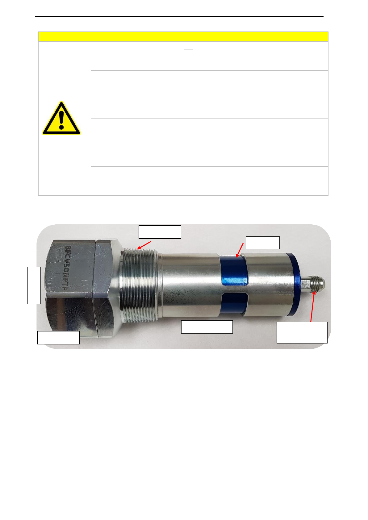
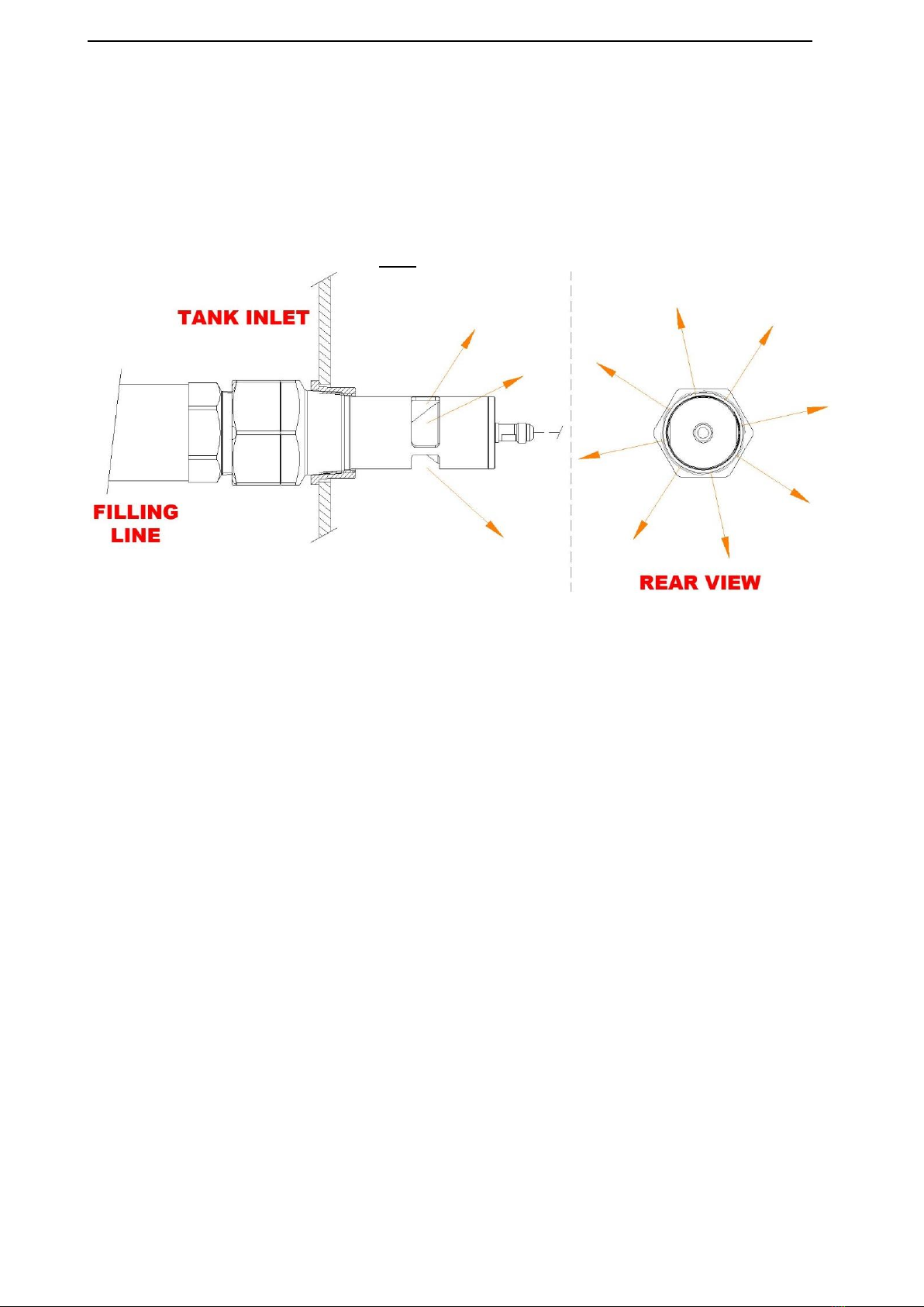
Figure 9 illustrates some of the key specifications of an internal Pilot Line, namely the means of mechanical
protection to help avoid excessive wear & tear, rupture, and other damage to the hose assembly. Internal
Pilot Lines are especially susceptible to damage (and subsequent failure) sustained within diesel fuel tanks
due to contact with such structures as internal baffles, and also fatigue due to “flexing” of the line in
response to the movement (i.e. turbulence and sloshing) of the fuel. Reference to the Banlaw FillSafe Zero
System Installation Procedure must be made prior to any attempt to install an internal Pilot Line assembly
to best avoid such failure modes. The Installation Procedure also includes hints on the most appropriate
methods, tools & accessories to use.
Unless otherwise noted by Banlaw, some of the key internal Pilot Line specifications and requirements
include:
1. Supplied by Banlaw, or otherwise manufactured strictly in accordance with Banlaw specifications.
2. Minimum ID (bore); 8mm (5/16”).
3. Maximum recommended overall length; 3.5m (11.5’). Contact Banlaw for applications requiring an
extended length.
4. Maximum recommended vertical head; 2.5m (8.2’) between Flow Control Valve location (lower)
and Level Sensor location (top). Contact Banlaw for applications requiring an extended head height.
5. Minimum (internal) safe working pressure (SWP); 2,500kPa (25 bar, 363psi).
6. Installed within a diesel tank;
a. To achieve the minimum possible Pilot Line length. Excess Pilot Line length should be
avoided.
b. Via a routing (pathway) which minimises the probability for contact between the Pilot Line
and structures within the tank, e.g. baffle plates, structural members, drop pipes, etc.
c. If passing through a baffle plate port (or similar opening), every effort is made to ensure
the Pilot Line is not held against the edge of such ports.
d. Any twisting or sharp (small) radius bends of the Pilot Line must be avoided. The swivel
action of the Pilot Line connections at the base of a BVLS model Level Sensor and at the
rear of a 2” BFCV50 model Flow Control Valve are to be tested (verified) prior to connecting
the Pilot Line –refer relevant PDS’s.
e. Other than the weight of the Pilot Line itself, no additional mass or tension (stretch) shall
be added to the hose assembly.
5INSTALLATION & COMMISSIONING GUIDELINES
This Installation & Commissioning Guide is general, and is not meant to replace or override installation
guidelines that arise out of a due diligence assessment of a Banlaw product for a specific (intended)
application.