Banner Sure Cross DX99 User manual

Datasheet
The Sure Cross®wireless system is a radio frequency network with integrated I/O that operates in most environments to eliminate the
need for wiring runs. DX99 wireless networks are formed around a Gateway, which acts as the wireless network master device, and one
or more Intrinsically Safe Nodes.
For addional informaon, updated
documentaon, and a list of accessories,
refer to Banner Engineering's website,
www.bannerengineering.com/wireless.
• Wireless industrial I/O device with two selectable discrete inputs and up to three
congurable thermocouple inputs (defaults to J-type)
•FlexPower®technology driven by one lithium primary baery integrated into the
housing
• One thermistor input used for integrated cold juncon compensaon (CJC)
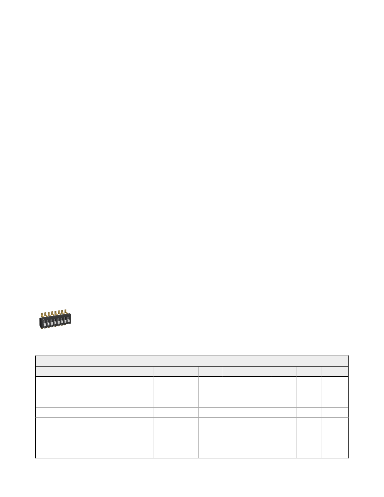
• DIP switches for user conguraon
• Frequency Hopping Spread Spectrum (FHSS) technology and Time Division Mulple
Access (TDMA) control architecture ensure reliable data delivery within the
unlicensed Industrial, Scienc, and Medical (ISM) band
• Transceivers provide bidireconal communicaon between the Gateway and
Node, including fully acknowledged data transmission
• Lost RF links are detected and relevant outputs set to user-dened condions
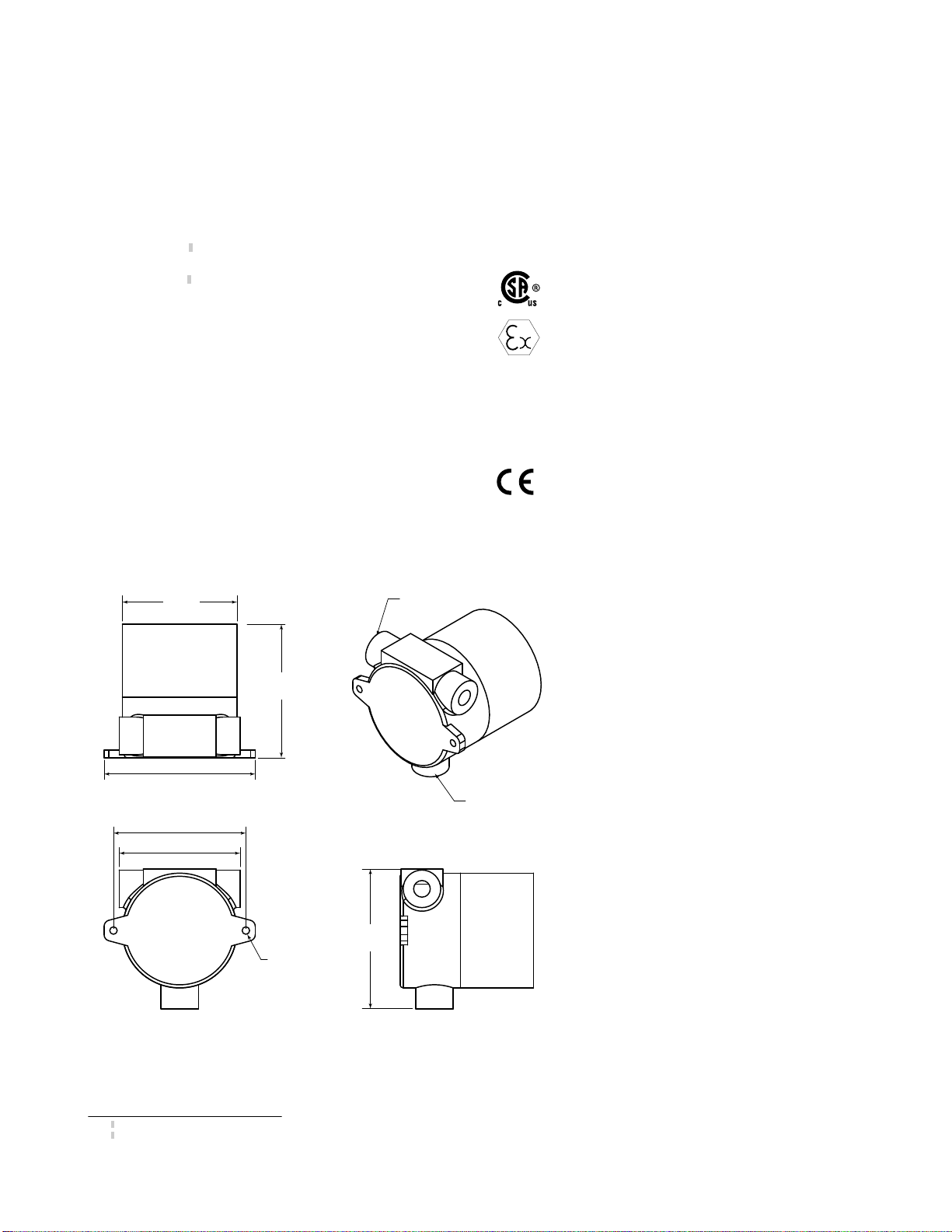
• DX99 Metal housings are cered for use in Class I, Division 1, Groups A, B, C, D;
Class II, Division 1, Groups E, F, G; Class III, Division 1; and Zone 0 (Category 1G) and
Zone 20 (Category 1D) when properly installed in accordance with the Naonal
Electrical Code, the Canadian Electrical Code, or applicable local codes/regulaons
Model Frequency I/O
DX99N9X1S2N0T4X0D0 900 MHz ISM Band Inputs: Two selectable discrete, three thermocouple, one thermistor (for CJC)
DX99N2X1S2N0T4X0D0 2.4 GHz ISM Band
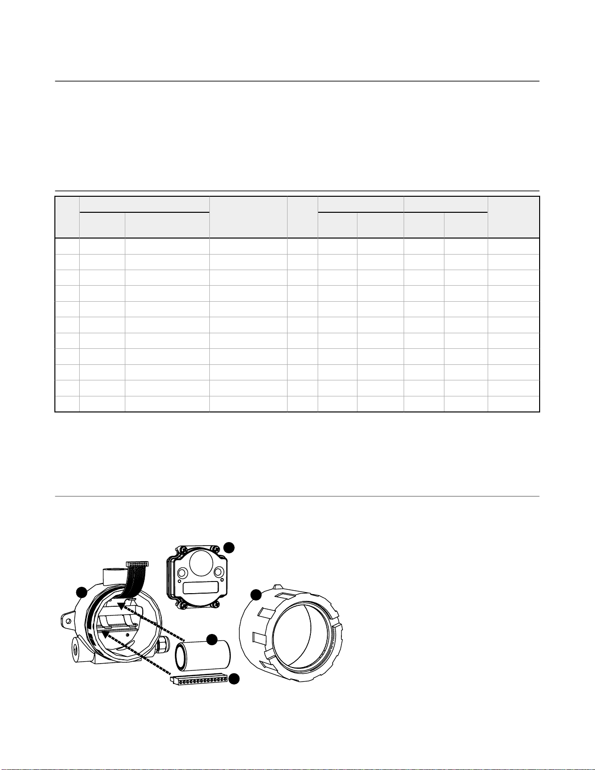
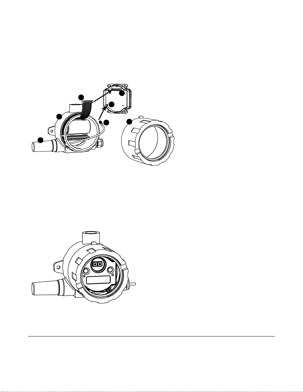
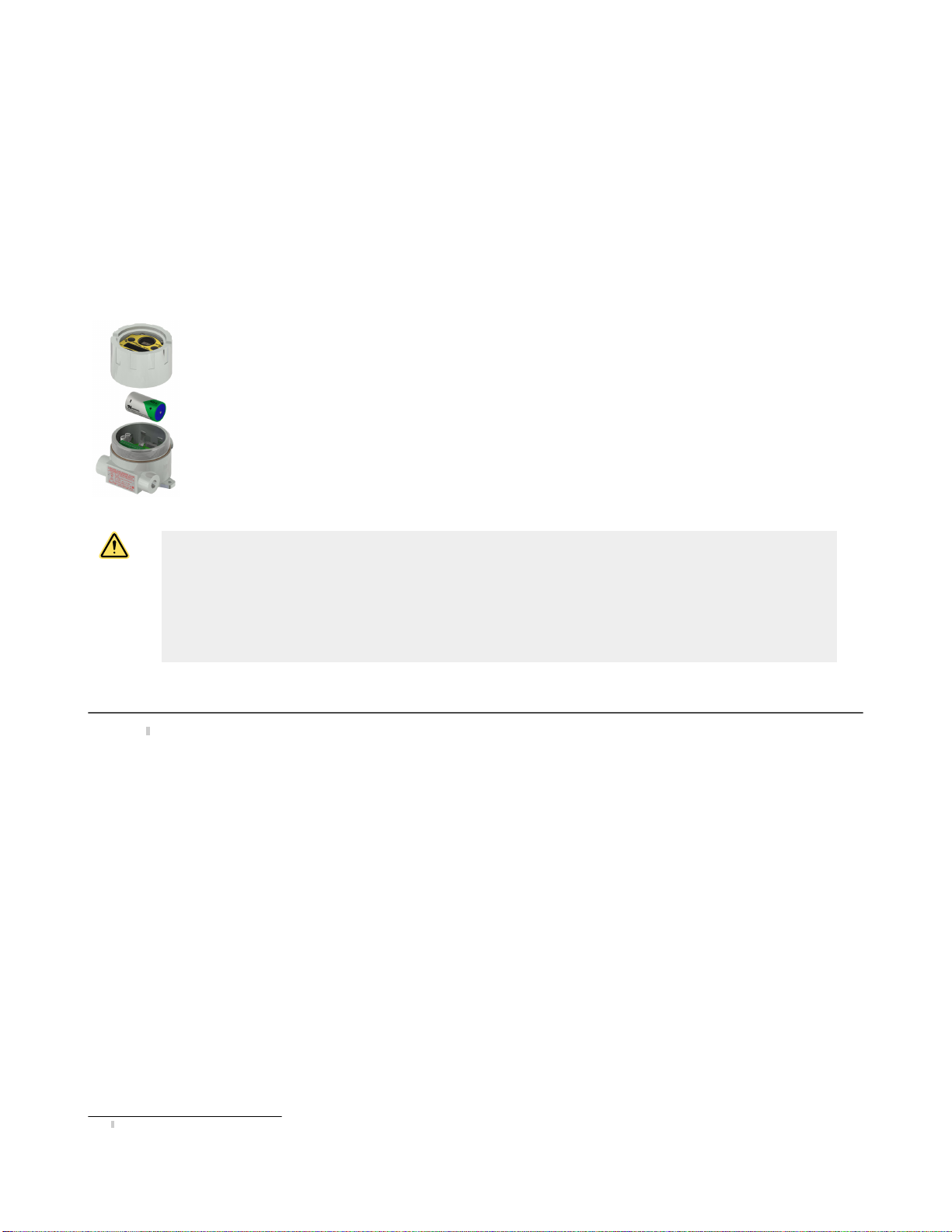
These models ship with the baery disconnected. To install the baery, refer to the baery replacement instrucons in this datasheet.
WARNING: Not To Be Used for Personnel Protecon
Never use this device as a sensing device for personnel protecon. Doing so could lead to serious injury or death.
This device does not include the self-checking redundant circuitry necessary to allow its use in personnel safety
applicaons. A sensor failure or malfuncon can cause either an energized or de-energized sensor output
condion.
Sure Cross®User Conguraon Tool
The User Conguraon Tool (UCT) oers an easy way to link I/O points in your wireless network, view I/O register values, and set
system communicaon parameters when a host system is not part of the wireless network. The soware runs on any computer with
the Windows Vista, Windows 7, Windows 8, or Windows 10 operang system.
Use a USB to RS-485 adapter cable to connect a standalone DX80 Gateway to the computer.
For DXM Controllers with an internal DX80 radio, connect a computer to the DXM Controller
using a USB or Ethernet connecon. Download the most recent revisions of the UCT soware
from Banner Engineering's website: www.bannerengineering.com/wireless.
The USB to RS-485 adapter cable is not required for the DXM Controller. For standalone DX80
Gateway devices use:
• USB to RS-485 adapter cable model BWA-UCT-900 for 1 Wa radios
• USB to RS-485 adapter cable model BWA-HW-006 for all other radios
Seng Up Your Wireless Network
To set up and install your wireless network, follow these steps.
Disconnect the power from your Sure Cross devices.
1. Congure the DIP switches of all devices.
Sure Cross®DX99 FlexPower Thermocouple Node (Metal
Housing)
Original Document
142681 Rev. O 3 November 2017
142681

2. If your device has I/O, connect the sensors to the Sure Cross devices. If your device does not have I/O, skip this step.
3. Refer to the wiring diagrams to apply power to all devices.
• For two LED models, the Gateway's LED 1 is solid green and the Node's LED 2 ashes red to indicate there is no radio link to
the Gateway.
• For one LED models, the Gateway's LED is solid green and the Node's LED ashes red to indicate there is no radio link to the
Gateway.
4. Form the wireless network by binding the Nodes to the Gateway. If the binding instrucons are not included in the datasheet,
refer to the product manual for binding instrucons.
5. Observe the LED behavior to verify the devices are communicang with each other.
• For two LED models, the Gateway's LED 1 is solid green and the Node's LED 1 ashes green to indicate it is communicang
with the Gateway.
• For one LED models, the Gateway's LED is solid green and the Node's LED ashes green to indicate it is communicang with
the Gateway.
6. Congure any I/O points to use the sensors connected to the Sure Cross devices.
7. Conduct a site survey between the Gateway and Nodes. If the site survey instrucons are not included in this datasheet, refer
to the product manual for detailed site survey instrucons.
8. Install your wireless sensor network components. If installaon instrucons are not included in this datasheet, refer to the
product manual for detailed installaon instrucons.
For addional informaon, including installaon and setup, weatherproong, device menu maps, troubleshoong, and a list of
accessories, refer to one of the following product manuals.
• Sure Cross®Wireless I/O Network Instrucon Manual: 132607
• Web Congurator Instrucon Manual (used with "Pro" and DX83 models): 134421
• Host Controller Systems Instrucon Manual: 132114
Congure the DIP Switches
Before changing DIP switch posions, disconnect the power. For devices with baeries integrated into the housing, remove the
baery(ies) for at least one minute. DIP switch changes are not recognized unl aer power is cycled to the device.
Accessing the DIP Switches of a Single-Chamber Metal Housing
The DIP switches are located behind the rotary dials.
To access the DIP switches, follow these steps:
1. Unscrew and remove the top of the DX99 metal housing. The top secon is the secon with the glass window.
2. Pull the radio cover secon o the bracket assembly. Two pins hold the radio cover to the bracket assembly.
3. Gently unplug the ribbon cable from the back of the radio cover.
4. Remove the black cover plate from the boom of the device's cover.
The DIP switches are located behind the rotary dials.
Aer making the necessary changes to the DIP switches, place the black cover plate back into posion and
gently push into place. Plug the ribbon cable in aer verifying that the blocked hole lines up with the
missing pin. Mount the cover back onto the bracket assembly.
DIP Switch Sengs
Switches
Device Sengs 1 2 3 4 5 6 7 8
Rotary switch address mode OFF*
Extended address mode ON
Temp °Fahrenheit OFF*
Temp °Celsius ON
High resoluon (0.1 degree)** OFF*
Low resoluon (1 degree) ON
Discrete sinking inputs OFF*
Discrete sourcing inputs ON
Sure Cross®DX99 FlexPower Thermocouple Node (Metal Housing)
2 www.bannerengineering.com - Tel: +1-763-544-3164 P/N 142681 Rev. O

Switches
Device Sengs 1 2 3 4 5 6 7 8
Thermocouple, J-Type OFF* OFF* OFF* OFF*
Thermocouple, B-Type OFF OFF OFF ON
Thermocouple, C-Type OFF OFF ON OFF
Thermocouple, D-Type OFF OFF ON ON
Thermocouple, E-Type OFF ON OFF OFF
Thermocouple, G-Type OFF ON OFF ON
Thermocouple, K-Type OFF ON ON OFF
Thermocouple, L-Type OFF ON ON ON
Thermocouple, M-Type ON OFF OFF OFF
Thermocouple, N-Type ON OFF OFF ON
Thermocouple, P-Type ON OFF ON OFF
Thermocouple, R-Type ON OFF ON ON
Thermocouple, S-Type ON ON OFF OFF
Thermocouple, T-Type ON ON OFF ON
Thermocouple, U-Type ON ON ON OFF
Modbus or UCT congured (overrides DIP switches) ON ON ON ON
* Default conguraon
** In high resoluon mode, the temperature = (Modbus register value) ÷ 20. In low resoluon mode, the temperature = (Modbus
register value) ÷ 2.
Address Mode
The SureCross wireless devices may use one of two types of addressing modes: rotary dial addressing or extended addressing. In rotary
dial address mode, the le rotary dial establishes the network ID and the right rotary dial sets the device ID. The wireless network is
restricted to a maximum of 16 devices.
Extended address mode uses a security code to "bind" Nodes to a specic Gateway. Bound Nodes can only send and receive
informaon from the Gateway to which they are bound. In extended address mode, wireless networks may contain up to 48 radio
devices. For more informaon on extended address mode, refer to the SureCross™Wireless I/O Network product manual.
The device ships in rotary dial address mode by default, with the DIP switch in the OFF posion. To use extended address mode, change
the DIP switch to the ON posion.
Discrete Input Type
Select the type of discrete input sensors to use with this device: sourcing (PNP) sensors or sinking (NPN) sensors.
Modbus/User Conguraon Tool (UCT) or DIP Switch Congured
In Modbus/UCT Congured mode, use the User Conguraon Tool (UCT) or a Modbus command to change the device parameters. DIP
switch posions 3 through 8 are ignored. In DIP Switch Congured mode, use the DIP switches to congure the parameters listed in the
table.
Temperature Resoluon
When set to high resoluon, temperature values are stored to the nearest tenth (0.1) of a degree (default posion). To measure
temperatures above 1600 degrees Fahrenheit or 1600 degrees Celsius, switch the DIP switch to the ON posion and use low resoluon
mode. In high resoluon, the device cannot store values larger than 1600.
Temperature Units
Use the DIP switch to specify if the temperature is stored in degrees Fahrenheit or Celsius. The default posion is OFF, seng the
temperature to Fahrenheit. For Celsius measurements, set this switch to the ON posion.
Sure Cross®DX99 FlexPower Thermocouple Node (Metal Housing)
P/N 142681 Rev. O www.bannerengineering.com - Tel: +1-763-544-3164 3

Thermocouple Type
Use DIP switches 5, 6, 7, and 8 to select the thermocouple type. The default posion is the OFF posion for all switches, seng the
thermocouple to a J-type thermocouple.
Supported Thermocouple Types
The thermocouple Node is congured, by default, to use J-type thermocouples. The following thermocouples are available by
conguring the Node.
Thermocouple Range °F Range °C
Type B 212 to 3,272 °F 100 to 1,800 °C
Type C 32 to 4,208 °F 0 to 2,320 °C
Type E -58 to 1,832 °F -50 to 1,000 °C
Type J -292 to 1,382 °F -180 to 750 °C
Type K -292 to 2,282 °F -180 to 1,250 °C
Type L -328 to 1,652 °F -200 to 900 °C
Type N 32 to 2,192 °F 0 to 1,200 °C
Type R 32 to 2,912 °F 0 to 1,600 °C
Type S 32 to 2,642 °F 0 to 1,450 °C
Type T -238 to 752 °F -150 to 400 °C
Type U -148 to 1,112 °F -100 to 600 °C
Terminal Blocks and Wiring
The complete control drawing is document 141513 at www.bannerengineering.com.
The GND connecon can be considered the same as the housing ground when using a stainless steel antenna feedthrough (model BWA-
HW-016 or BWA-HW-017). When the stainless steel antenna feedthroughs are not used, the GND connecon is isolated from the metal
housing.
GND
DI2
GND
DI1
A6
A5
A4+
A4−
A3+
A3−
A2+
A2−
A1+
A1−
Ax+ and Ax–. Analog IN x. Analog inputs for devices requiring more than one
connecon, such as thermocouples or RTDs. When there is no Ax–, use Ax+ as an
analog input.
DIx. Discrete IN x
GND. Ground/dc common connecon
Control Drawings
Sure Cross®DX99 FlexPower Thermocouple Node (Metal Housing)
4 www.bannerengineering.com - Tel: +1-763-544-3164 P/N 142681 Rev. O

Thermocouple Node - Single Chamber Metal Housing (DX99..D)
For the DX99..D with the single baery supply.
Hazardous Location
9
10
11
9
10
10
A4−
DI2
GND
A4+
GND
DI1
A5
A3+
A3−
A2+
A2−
A1+
A1−
Sure Cross Device
A6
Sinking
Input 2
Sinking
Input 1
Thermistor
Input Wiring
Thermocouple 2
Thermocouple 3
Thermocouple 1
Enty Parameters - 9
Uo/Voc 3.9 V
Io/Isc 1.20 mA
Po 1.17 mW
Co/Ca 670 μF
Lo/La 27.7 H
Enty Parameters - 10
Uo/Voc 3.9 V
Io/Isc 7.88 mA
Po 7.69 mW
Co/Ca 670 μF
Lo/La 644 mH
Enty Parameters - 11
Uo/Voc 3.9 V
Io/Isc 68.59 mA
Po 66.88 mW
Co/Ca 670 μF
Lo/La 8.5 mH
Metal Enclosure
CSA C/US Class I, Division 1, Groups A, B, C, D
Class II, Division 1, Groups E, F, G
Class III, Division 1
Class I, Zone 0, Group IIC
LCIE/ATEX Group IIC, Zone 0
Dust, Zone 20
Models
DX99N9X1S2N0T4X0D0 DX99N2X1S2N0T4X0D0
LED Behavior for the Nodes
Nodes do not sample inputs unl they are communicang with the Gateway. The radios and antennas must be a minimum distance
apart to funcon properly. Recommended minimum distances are:
2.4 GHz 65 mW radios: 1 foot
900 MHz 150 mW and 250 mW radios: 6 feet
900 MHz 1 Wa radios: 15 feet
LED 1 LED 2 Node Status
Flashing green Radio Link Ok
Flashing red Flashing red Device Error
Flashing red, 1 per 3 sec No Radio Link
Sure Cross®DX99 FlexPower Thermocouple Node (Metal Housing)
P/N 142681 Rev. O www.bannerengineering.com - Tel: +1-763-544-3164 5

Storage and Sleep Modes
Storage Mode (applies to baery-powered models only)—While in storage mode, the radio does not operate. All Sure Cross®radios
powered from an integrated baery ship from the factory in storage mode to conserve the baery. To wake the device, press and hold
buon 1 for 5 seconds. To put any FlexPower®or integrated baery Sure Cross radio into storage mode, press and hold buon 1 for 5
seconds. The radio is in storage mode when the LEDs stop blinking, but in some models, the LCD remains on for an addional minute
aer the radio enters storage mode. Aer a device has entered storage mode, you must wait 1 minute before waking it.
Sleep Mode (applies to both baery and 10–30 V dc powered models)—During normal operaon, the Sure Cross radio devices enter
sleep mode aer 15 minutes of operaon. The radio connues to funcon, but the LCD goes blank. To wake the device, press any
buon.
Modbus Register Table (High Resoluon Mode, DX99)
I/O Modbus Holding Register I/O Type Units I/O Range Holding Register Value Terminal
Block Labels
Gateway Any Node Min. Max. Min.
(Dec.) Max.
(Dec.)
1 1 1 + (Node# × 16) Discrete IN 1 - 0 1 0 1 DI1
2 2 2 + (Node# × 16) Discrete IN 2 - 0 1 0 1 DI2
3 3 3 + (Node# × 16) Thermocouple IN 1 °F/°C -1638.3 +1638.4 0 65535 A1+/A1-
4 4 4 + (Node# × 16) Thermocouple IN 2 °F/°C -1638.3 +1638.4 0 65535 A2+/A2-
5 5 5 + (Node# × 16) Thermocouple IN 3 °F/°C -1638.3 +1638.4 0 65535 A3+/A3-
6 6 6 + (Node# × 16) Thermistor IN °F/°C -1638.3 +1638.4 0 65535 A4+/A4-
7 7 7 + (Node# × 16) Reserved
8 8 8 + (Node# × 16) Device Message
...
15 15 15 + (Node# × 16) Control Message
16 16 16 + (Node# × 16) Reserved
In high resoluon mode, the temperature = (Modbus register value) ÷ 20. In low resoluon mode, the temperature is (Modbus register
value) ÷ 2.
Temperature values are stored as signed values in the Modbus register. A 0 in the register is interpreted as 0°; and 65535 in the register
(0xFFFF) is interpreted as −1 ÷ 20 = −0.05° in high resoluon mode and –1 ÷ 2 = –0.5° in low resoluon mode.
Assembly
Follow these steps to assemble your DX99...D Metal Housing with Dome Antenna model. The DX99 unit ships as a complete unit,
including the radio core, housing, and integrated baery. One terminal header is also included in the shipment. To unpack and wire the
unit:
2
1
3
4
5
Figure 1. Installing the Baery and Terminal Header
Sure Cross®DX99 FlexPower Thermocouple Node (Metal Housing)
6 www.bannerengineering.com - Tel: +1-763-544-3164 P/N 142681 Rev. O

Step 1. Open the end with the glass window (5) and gently li the radio core unit (4) and the space frame it sits on up. The core unit
connects to the space frame using two pins and the radio core is connected to the wiring board with a ribbon cable.
Step 2. Disconnect the ribbon cable from the radio.
Step 3. Insert the baery (2) into the baery holder, verifying the posion and negave poles of the baery are posioned according to
the markings on the board.
Step 4. Install the terminal header (3) onto the terminal pins.
Step 5. Insert your sensor wires through a cable gland and one of the two 1/2-inch NPT ports. Wire the sensor wires into the terminal
header (3) according to the control drawings, p/n 141513. Use a cable gland cered for your region and environment. For a waterproof
seal, refer to the waterproong instrucons in Banner document 132607.
7
1
2
3
5
6
4
Figure 2. Installing and Connecng the Antenna
Step 6. To install the dome antenna (2), thread the antenna cable through the 1/2-inch NPT port and screw the dome antenna to the
1/2-inch NPT port.
Step 7. Connect the antenna cable (3) to the radio unit’s antenna connector (5). (You may need to separate the space frame from the
radio to do this.)
Step 8. Gently install the ribbon cable (4) into the ribbon cable pins (6), verifying the ribbon cable is seated on both rows of pins.
Step 9. Reconnect the space frame (not shown) to the radio core unit.
Step 10. Place the radio unit into the housing and gently push down unl the spacer frame pin holes rest on the edge of the metal
housing.
Figure 3. Final Assembly
Step 11. Close the metal cover rmly and lock closed using the set screw.
Installing or Replacing the Baery (DX99...D Models)
To install or replace the lithium "D" cell baery in the metal housings, follow these steps.
1. Unscrew the lid of the metal enclosure.
2. Li the radio out of the metal enclosure and pull the spacer frame o the back side of the radio.
3. Disconnect the radio by unplugging the ribbon cable from the radio board and set aside the radio and spacer frame.
Sure Cross®DX99 FlexPower Thermocouple Node (Metal Housing)
P/N 142681 Rev. O www.bannerengineering.com - Tel: +1-763-544-3164 7

4. If you are replacing an exisng baer, remove the discharged baery.
5. Insert a new baery. Only use a 3.6 V lithium baery from Xeno, model number XL-205F.
6. Verify the baery’s posive and negave terminals align to the posive and negave terminals of the baery holder mounted
within the case. Cauon: There is a risk of explosion if the baery is replaced incorrectly.
7. Wait two minutes.
8. Insert the ribbon cable through the center of the spacer frame, then plug the ribbon cable back into the radio board.
9. Insert the radio back onto the spacer frame pins. Push the radio and spacer frame assembly back into the enclosure unl it is
seated.
10. Screw on the lid and ghten.
11. Aer replacing the baery, allow up to 60 seconds for the device to power up.
12. Properly dispose of your used baery according to local regulaons by taking it to a hazardous waste collecon site, an e-waste
disposal center, or other facility qualied to accept lithium baeries.
As with all baeries, these are a re, explosion, and severe burn hazard. Do not burn or expose them
to high temperatures. Do not recharge, crush, disassemble, or expose the contents to water.
The baery may be replaced in explosive gas atmospheres. Replacement baery model number:
BWA-BATT-001. For pricing and availability, contact Banner Engineering.
WARNING:
• Do not replace baery when an explosive dust atmosphere may be present.
• The replacement baery MUST be a Banner approved baery, model number BWA-BATT-001. Use of a
dierent baery will VOID the intrinsic safety rang of this device and may result in an explosion!
• When replacing the baery, the negave end of the baery holder is the side by the large capacitors. This
side is marked with a minus (−) sign.
• Do not aempt to recharge the baery. These baeries are not rechargeable. Recharging may cause
serious injury to personnel or damage the equipment. Replace only with factory recommended baeries.
Specicaons
Radio Range1
900 MHz, 150 mW: Up to 4.8 km (3 miles)
2.4 GHz, 65 mW: Up to 3.2 km (2 miles)
Minimum Separaon Distance
900 MHz, 150 mW and 250 mW: 2 m (6 )
2.4 GHz, 65 mW: 0.3 m (1 )
Transmit Power
900 MHz, 150 mW: 21 dBm (150 mW) conducted
2.4 GHz, 65 mW: 18 dBm (65 mW) conducted, less than or equal to 20 dBm
(100 mW) EIRP
900 MHz Compliance
FCC ID TGUDX80 - This device complies with FCC Part 15, Subpart C, 15.247
IC: 7044A-DX8009
2.4 GHz Compliance
FCC ID UE300DX80-2400 - This device complies with FCC Part 15, Subpart C,
15.247
ETSI EN 300 328 V1.8.1 (2012-06)
IC: 7044A-DX8024
Supply Voltage
3.6 V dc low power opon from an internal baery
Power Consumpon
Consumpon: Applicaon dependant
Housing
Glass and cast aluminium w/ chromang and chemically resistant paint
(outside only)
Antenna Connecon
Ext. Reverse Polarity SMA, 50 Ohms
Max Tightening Torque: 0.45 N·m (4 lbf·in)
Interface
Two bi-color LED indicators, Two buons, Six character LCD
Wiring Access
Two 1/2-inch NPT ports, one 3/4-inch NPT port (internal threads)
Spread Spectrum Technology
FHSS (Frequency Hopping Spread Spectrum)
Link Timeout
Gateway: Congurable via User Conguraon Tool (UCT) soware
Node: Dened by Gateway
1Radio range is with the 2 dB antenna that ships with the product. High-gain antennas are available, but the range depends on the environment and line of sight. Always verify your wireless network's
range by performing a Site Survey.
Sure Cross®DX99 FlexPower Thermocouple Node (Metal Housing)
8 www.bannerengineering.com - Tel: +1-763-544-3164 P/N 142681 Rev. O

Thermocouple Inputs
Sample Rate: 1 second
Report Rate: 16 seconds
Accuracy: 0.1% of full scale reading + 0.8 °C
Resoluon: 0.1 °C, 24-bit A/D converter
Thermistor Input (used for CJC)
Model: BWA-THERMISTOR-001
Accuracy: 0.4 °C (10 °C to 50 °C); Up to 0.8 °C (−40 °C to 85 °C)
Resoluon: 0.1 °C, 24-bit A/D converter
Discrete Inputs
Rang: See control drawing
Sample Rate: 1 second
Report Rate: On change of state
Discrete Input ON Condion
PNP: Greater than 8 V
NPN: Less than 0.7 V
Discrete Input OFF Condion (DX99 Models)
PNP: Less than 4.5 V
NPN: Greater than 2.2 V or open
Environmental Rang2
IEC IP68
Operang Condions3
–40 °C to +65 °C (–40 °F to +149 °F) (Electronics); –20 °C to +80 °C (–4 °F to
+176 °F) (LCD)
95% maximum relave humidity (non-condensing)
Radiated Immunity: 10 V/m (EN 61000-4-3)
Shock and Vibraon
IEC 68-2-6 and IEC 68-2-27
Shock: 30g, 11 millisecond half sine wave, 18 shocks
Vibraon: 0.5 mm p-p, 10 to 60 Hz
Cercaons
CSA: Class I, Division 1, Groups A, B, C, D; Class II, Division 1, Groups E, F, G;
Class III, Division 1 (Ex ia IIC T4 / AEx ia IIC T4) Cercate: 2008243
LCIE/ATEX: Zone 0 (Category 1G) and 20 (Category 1D), Temperature Class T4
(II 1 GD / Ex ia IIC T4 Ga / Ex ia IIIC T82°C Da IP68) Cercate: LCIE 08 ATEX
6098 X
Special Condions for Safe Use imposed by Intrinsic Safety Cercate LCIE 08
ATEX 6098 X: Ambient temperature range is –40 to 70 °C. Sure Cross®DX99
FlexPower devices can only be connected to Intrinsically Safe cered
equipment or simple apparatus as dened by EN 60079-11. All connected
equipment must comply with the Enty Parameters (Safety Parameters) listed
in the Control Drawings (p/n 141513). The device must only use a lithium
baery manufactured by XENO, type XL-205F.
1725
Metal Housing Dimensions
115 mm [4.5 in]
126 mm [4.96 in]
145 mm
[5.7 in]
125.5 mm
[4.94 in]
110 mm
[4.33 in]
127 mm
[5 in]
Ø7mm
[0.27 in]
3/4” NPT internal
threads
1/2” NPT internal
threads (2)
2Refer to the Sure Cross®Wireless I/O Networks Instrucon Manual (p/n 132607) for installaon and waterproong instrucons.
3Operang the devices at the maximum operang condions for extended periods can shorten the life of the device.
Sure Cross®DX99 FlexPower Thermocouple Node (Metal Housing)
P/N 142681 Rev. O www.bannerengineering.com - Tel: +1-763-544-3164 9

Accessories
Metal Housing Accessories
BWA-9O2-001
• Dome antenna
• 2 dBi, 18-inch cable, 1/2" SS NPT
Port, 900 MHz
BWA-9O2-002
• Dome antenna
• 2 dBi, 18-inch cable, 3/4" SS NPT
Port, 900 MHz
BWA-2O2-001
• Dome antenna
• 2 dBi, 18-inch cable, 1/2" SS NPT
Port, 2.4 GHz
BWA-2O2-002
• Dome antenna
• 2 dBi, 18-inch cable, 3/4" SS NPT
Port, 2.4 GHz
BWA-HW-016
• Antenna Feedthrough, Stainless Steel
• 1/2" NPT
BWA-HW-017
• Antenna Feedthrough, Stainless Steel
• 3/4" NPT
BWA-AXFS0130
• AXF™Explosion-Proof Antenna
Coupler
BWA-HW-012
• DX99 Antenna Extension Pack
• M4-0.7 × 20 black steel pan head screw
• Flexible antenna cable 12" SMA male to SMA female
BWA-HW-037
• Clear plasc retaining ring for DX99 metal housings
• Qty: 10
Thermistor Probes
BWA-THERMISTOR-PROBE-001
• Temperature sensor with thermistor PS103G2
• Beta Value(K) 0 ~50°C: 3575
• Base thermistor accuracy of 0.2%
•Operang Temperature Range: –20 °C to +105 °C
• Maximum Power Rang: 30 mW at 25 °C; derated to 1 mW at 125 °C
•Dissipaon Constant: 1 mW/°C
• Plated nickel nish; PVC insulaon
( 3.2 )
35 mm
6 mm
( 4)
20 mm
72 mm
Tube
Included with Device (Metal Housing)
The following items ship with the metal housings.
• BWA-9O2-C (900 MHz) or BWA-2O2-C (2.4 GHz): Antenna, 2 dBd Omni, Rubber Swivel RP-SMA Male. (Not included with
Internal antenna models)
• BWA-HW-025: Cable pack, Flexible antenna cable, terminal strip
Sure Cross®DX99 FlexPower Thermocouple Node (Metal Housing)
10 www.bannerengineering.com - Tel: +1-763-544-3164 P/N 142681 Rev. O

Warnings
Install and properly ground a qualied surge suppressor when installing a remote antenna system. Remote antenna conguraons installed without surge suppressors invalidate the
manufacturer's warranty. Keep the ground wire as short as possible and make all ground connecons to a single-point ground system to ensure no ground loops are created. No surge
suppressor can absorb all lightning strikes; do not touch the Sure Cross®device or any equipment connected to the Sure Cross device during a thunderstorm.
Exporng Sure Cross®Radios. It is our intent to fully comply with all naonal and regional regulaons regarding radio frequency emissions. Customers who want to re-export this product to a
country other than that to which it was sold must ensure the device is approved in the desnaon country. A list of approved countries appears in the Radio Cercaons secon of the
product manual. The Sure Cross wireless products were cered for use in these countries using the antenna that ships with the product. When using other antennas, verify you are not
exceeding the transmit power levels allowed by local governing agencies. Consult with Banner Engineering Corp. if the desnaon country is not on this list.
Banner Engineering Corp. Limited Warranty
Banner Engineering Corp. warrants its products to be free from defects in material and workmanship for one year following the date of shipment. Banner Engineering Corp. will repair or
replace, free of charge, any product of its manufacture which, at the me it is returned to the factory, is found to have been defecve during the warranty period. This warranty does not cover
damage or liability for misuse, abuse, or the improper applicaon or installaon of the Banner product.
THIS LIMITED WARRANTY IS EXCLUSIVE AND IN LIEU OF ALL OTHER WARRANTIES WHETHER EXPRESS OR IMPLIED (INCLUDING, WITHOUT LIMITATION, ANY WARRANTY OF
MERCHANTABILITY OR FITNESS FOR A PARTICULAR PURPOSE), AND WHETHER ARISING UNDER COURSE OF PERFORMANCE, COURSE OF DEALING OR TRADE USAGE.
This Warranty is exclusive and limited to repair or, at the discreon of Banner Engineering Corp., replacement. IN NO EVENT SHALL BANNER ENGINEERING CORP. BE LIABLE TO BUYER OR ANY
OTHER PERSON OR ENTITY FOR ANY EXTRA COSTS, EXPENSES, LOSSES, LOSS OF PROFITS, OR ANY INCIDENTAL, CONSEQUENTIAL OR SPECIAL DAMAGES RESULTING FROM ANY PRODUCT
DEFECT OR FROM THE USE OR INABILITY TO USE THE PRODUCT, WHETHER ARISING IN CONTRACT OR WARRANTY, STATUTE, TORT, STRICT LIABILITY, NEGLIGENCE, OR OTHERWISE.
Banner Engineering Corp. reserves the right to change, modify or improve the design of the product without assuming any obligaons or liabilies relang to any product previously
manufactured by Banner Engineering Corp. Any misuse, abuse, or improper applicaon or installaon of this product or use of the product for personal protecon applicaons when the
product is idened as not intended for such purposes will void the product warranty. Any modicaons to this product without prior express approval by Banner Engineering Corp will void the
product warranes. All specicaons published in this document are subject to change; Banner reserves the right to modify product specicaons or update documentaon at any me.
Specicaons and product informaon in English supersede that which is provided in any other language. For the most recent version of any documentaon, refer to:
www.bannerengineering.com.
Sure Cross®DX99 FlexPower Thermocouple Node (Metal Housing)
©Banner Engineering Corp. All rights reserved
Table of contents
Other Banner Network Hardware manuals
Popular Network Hardware manuals by other brands

MANNL ELEKTRONIK
MANNL ELEKTRONIK WIFI232-S user manual

Gigamon
Gigamon GigaVUE-HC3 Hardware installation guide

Ubiquiti
Ubiquiti UF-Instant quick start guide

DG Technologies
DG Technologies lodestar user manual

Allnet
Allnet ALL-MC116SV-VDSL2 user manual

FRIEDHELM LOH
FRIEDHELM LOH RITTAL META O.R.V3 Series installation manual