AVYCON AVR NT832A User manual

QUICK START GUIDE
NETWORK VIDEO RECORDER
AVR NT832A

TABLE OF CONTENT
1 Notes .................................................................................................................................................................... 1
2 Packing Check ................................................................................................................................................. 1
3 HDD Installation ............................................................................................................................................... 1
4 Rear Panel Instruction ................................................................................................................................... 2
5 Startup & Shutdown ...................................................................................................................................... 2
6 System Login .................................................................................................................................................... 3
7 Disk Settings ..................................................................................................................................................... 3
8 Network Configuration & Add IP Camera .............................................................................................. 3
9 RAID Settings .................................................................................................................................................... 5
10 Recording Settings ....................................................................................................................................... 6
11 NAT ...................................................................................................................................................................... 6
12 Analog Camera Connection ..................................................................................................................... 7
13 Manual Recording ......................................................................................................................................... 7
14 Playback .......................................................................................................................................................... 8

1 NETWORK VIDEO RECORDER | AVR SERIES | NOTES
1 Notes
Please read this instruction carefully before using the product and keep it for further
reference.
All the examples and pictures used here are for reference only.
The contents of this manual are subject to change without notice.
This device should be operated only from the type of power source indicated on the
marking label. The voltage of the power must be verified before using the same.
2 Packing Check
Please check the device and the accessories after getting the device. If there are any
damages, shortages or defects, please contact your dealer immediately.
3 HDD Installation
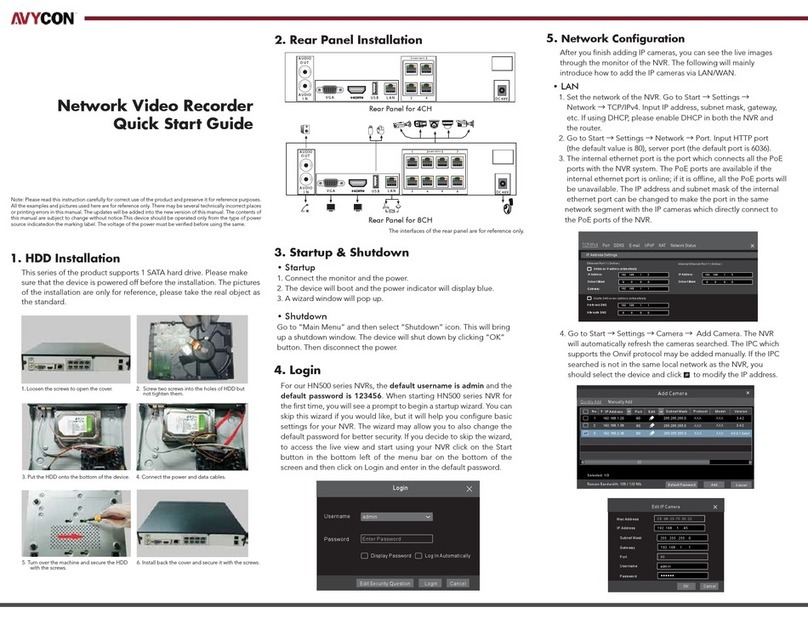
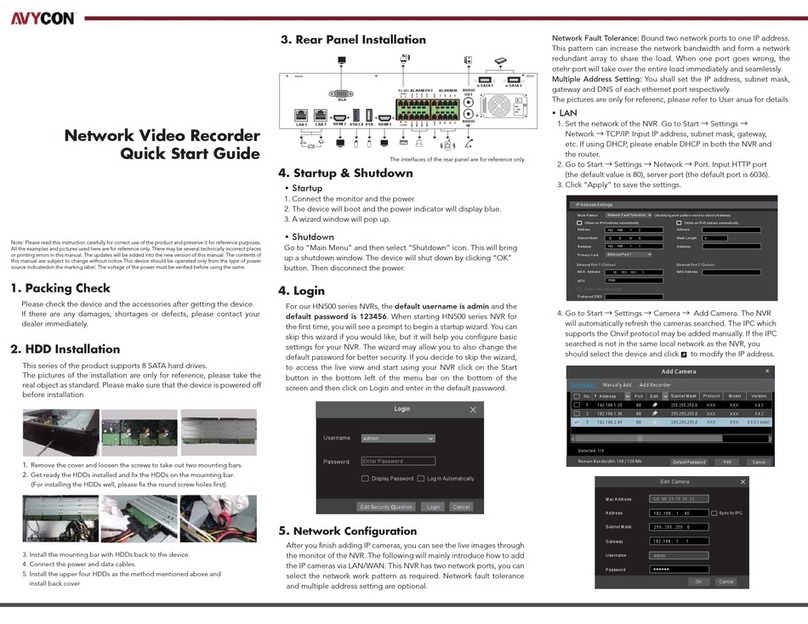
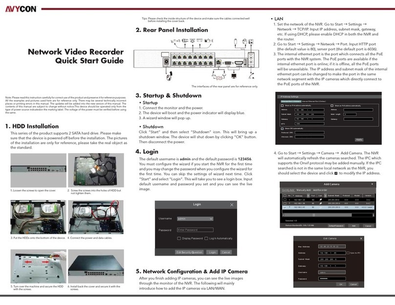
This series of the product supports 8 SATA hard drives. The pictures of the installation are
only for reference, please take the real object as the standard. Please make sure that the
device is powered o before the installation.
①Remove the cover and loosen the screws to take out two rails.
②Fasten the HDDs onto the rails.
③Install the two rails with HDDs back to the device ( It is recommended to install the posts
supporting the upper rail as shown on the above right ).
④Connect the power and data cables.
⑤Install back the cover and secure it with the screws.

4. Rear Panel Instruction
5 Startup & Shutdown
Startup
①Connect the monitor and the power.
②The device will boot and the power indicator will display blue.
③A wizard window will pop up.
Shutdown
Click “Start” and then select “Shutdown” icon. This will bring up a shutdown window. The
device will shut down by clicking “OK” button. Then disconnect the power.
2 NETWORK VIDEO RECORDER | AVR SERIES | REAR PANEL INSTRUCTION
Internet
Audio input connector
Audio output connector
Connector for a microphone
Video input connector
HDMI connector; connect to monitor
Connect to monitor
AUDIO OUT
MIC IN
Connect to USB storage devices or USB mouses
Name Description
VIDEO IN
AUDIO IN
VGA
HDMI
CVBS
RS 485
USB3.0/USB
CVBS output connector
RS 485 connector; connect to a keyboard
Connectors for alarm input devices, like sensors
Relay output; connectors for external alarm output devices
ALARM OUT
Connector for a PTZ device; (Y is TX+; Z is TX-)
P/Z
GND & ALARM IN
LAN1/2 Network connector

6 System Login
You must configure the wizard if you start the DVR for the first time. Choose the language.
Then set the data, time and zone as needed. After that, set the login password.
The default username is admin. Set your own password when you use the wizard for the
first time. Enable pattern lock and click “Edit” to set the pattern lock. Then set security
questions and answers. It is important for you to remember these answers, or you will not
be able to reset your password. Click “Next” to continue.
7 Disk Settings
You can view the disk number, disk capacity of the DVR and serial number, Read/Write
status of the disk. Click “Format” to format the disk. Click “Next” to continue.
8 Network Configuration & Add IP Camera
①Select the work pattern and then enter IP address, subnet mask, gateway, etc. If using
DHCP, please enable DHCP in both the DVR and the router.
The multiple address setting or network fault tolerance can be chosen and configured.
Network Fault Tolerance: Bind two network ports to one IP address. This pattern can
increase the network bandwidth and form a network redundant array to share the load.
When one port goes wrong, the other port will take over the entire load immediately
and seamlessly.
Multiple Address Setting: You shall set the IP address, subnet mask, gateway and DNS
of each Ethernet port respectively.
3 NETWORK VIDEO RECORDER | AVR SERIES | SYSTEM LOGIN
Username
Admin Password Setup
New Password
Confirm Password
Pattern Lock
admin
Wizard
xxxxxx
xxxxxx
Display Password
Enable
Next
Log In Automatically
Previous
Edit

4 NETWORK VIDEO RECORDER | AVR SERIES | SYSTEM LOGIN
Wizard
Obtain an IP address automatically
AddressAddress
Obtain an IP address automatically
192 . 168 . 1 . 2 192 . 168 . 2 . 2
255 . 255 . 255 . 0 255 . 255 . 255 . 0
192 . 168 . 1 . 1 192 . 168 . 2 . 1
Subnet MaskSubnet Mask
GatewayGateway
Ethernet Port 1 ( Online ) Ethernet Port 2 ( Offline )
Obtain DNS automatically
HTTP Port
Obtain DNS automatically
Default Route
HTTPS Port
Sever Port
... ...
... . ..
Preferred
DNSPreferred
DNS
Alternate
DNSAlternate
DNS
NextPrevious
80
Cancel
443
Ethernet Port 1
6036
Multiple Address Setting
Network Settings
Work Pattern
②Enter HTTP port (the default value is 80) and server port (the default port is 6036).
③Add Camera. Click “Next” to go to the following interface.
3.4.2
3.4.2
4.0.0.1.beta1
VersionAdd
+_
_
_
+
+
80
80
80
No.AddressEditPortProtocol
1
Model
2
3
3
192.168.1.20
192.168.1.38
XXX
192.168.2.45
XXX
XXX
XXX
XXX
XXX
Wizard
Network SettingsAdd Camera
Delete
No.AddressEdit
IP Camera NameProtocol
1
Status
2
4
[A01] Camera1
Add All
RefreshDelete All
Remain Bandwidth: 20 / 40 Mb
[A02] Camera2
[A03] Camera3
[A04] Camera4

Click “Refresh” to refresh the list of online IP cameras which are in the same local network
with the DVR. Click + to add the searched camera. Click “Add All” to add all the cameras in
the list. Click to delete the added camera. Click “Delete All” to delete all the added
cameras.
5 NETWORK VIDEO RECORDER | AVR SERIES | RAID SETTINGS
④Click to edit an IP camera as shown on the above left. Enter the new IP address,
subnet mask, gateway, username and password of the camera. Click “OK” to save the
settings.
Click to edit the added camera as shown on the above right. Enter the new camera
name, IP address, port, username and the password of the camera. You can click “Test”
to test the eectiveness of the input information. Click “OK” to save the settings. Only
the camera name can be changed for analog cameras or online IP cameras you added.
Click “Next” to continue.
9 RAID Settings
Check “Enable RAID” and then the device will automatically reboot. Then enter Wizard and
create an array. The authority authentication box will pop up when creating an array.
Please enter the username (admin) and password you set before.
Camera Name
Address
Model
XXX
Edit Camera
9008
192.168. 1 . 58
admin
XXX
Port
Username
Protocol
Password
IP Camera 1
OKTestCancel
Sync to IPC
Mac Address
Address
Edit IP
192 .168 . 1 . 45
admin
255 . 255 . 255 . 0
192 .168 . 1 . 1
Subnet Mask
Username
Gateway
Password
OK Cancel
CE :98 :23 :75 :35 :22
Array Name
Array Type
Physical Disk
Global Hot Spares
Array Capacity
Test
RAID5
WizardWizard
NextNextCancel
Cancel
PreviousPrevious
Disk ModeDisk ModeCreate an array
1 2
Enable RAID
3 4 5 7
68
None
0GB
Set array name, array type and physical disk as needed (See Disk Management of User
Manual for more details). Then click “Next”.

6 NETWORK VIDEO RECORDER | AVR SERIES | RESORD SETTINGS
10 Record Settings
Two record modes: auto and manual.
Auto Mode: Select one auto mode in the interface as shown below and then click “Next” to
save the settings. Click “Advanced” to self-define a record mode.
Manual Mode: Set the “Sensor Record”, “Motion Record”, “Analytics Record” and
“Schedule Record” of each camera. Please enable the record as needed. Click “Next” to
continue.
11 NAT
You can enable the NAT function in the interface or set it in the network configuration after
exiting the wizard. You can scan the QR code through the mobile surveillance APP for iOS
or Android to easily view your cameras.
Web Access Through NAT Function
① Go to Start → Settings → Network → NAT tab. Enable NAT and select the NAT access
type(NAT1.0 or NAT2.0). Click “Apply” to save the parameters.
Wizard
Mode
Next
Advanced
PreviousCancel
Network SettingsAdd CameraDisk SettingsRecord Settings
Auto
Motion Record
Sensor Record
Motion Record+Sensor Record
Always(24x7)Record+Motion Record
Always(24x7)Record+Sensor Record
Always(24x7)Record+MotionRecord+Sensor Record
Always(24x7)Record+MotionRecord+Sensor Record+AnalyticsRecord
Access Type
Enable
NAT2.0(d2020.autonat.com:7968)
Visit Address www.autonat.com
Apply
NAT
NAT Status Success

7 NETWORK VIDEO RECORDER | AVR SERIES | ANALOG CAMERA CONNECTION
Enter the visit address in the address bar of your browser and then press enter to go to the
following interface. If you are the first time to access the NAT, you shall download and
install the plug-in according to the popup tips. After installing the plug-in successfully, it
will appear the login box.
Device Serial Number: Click Start → Settings → Network→ NAT to view the serial number.
Username: The username of the DVR. The default username is admin.
Password: The password of the DVR. The password is set by yourself when you configure
the wizard for the first time.
12 Analog Camera Connection
First connect the camera to the DVR. Then go to Start → Settings → Camera
→ Manage Camera → Camera Signal to checkmark the video mode. The actual signals
input shall correspond to the video mode. Please refer to User Manual for details.
13 Manual Recording
Before recording, please install a HDD. In the live interface you can see the menu toolbar.
Click button to start recording. Click it again to stop recording. You can also click
to check the status of the recording.
Enter Password
Enter Username
Login
Enter device serial number

8 NETWORK VIDEO RECORDER | AVR SERIES | PLAYBACK
14 Playback
Instant playback
Click on the tool bar at the bottom of the preview camera window to play back the
record from 5 minutes ago or right click to select “Instant Playback” and then select the
instant playback time to play back the record.
General playback
Click on the tool bar at the bottom of the live view interface or click Start → Playback to
go to the playback interface as shown below. You can also add the playback cameras
manually. Click in the playback window to pop up the “Add Camera” window. Check the
cameras in the window and then click “Add” to add playback camera. The record files of
the added playback camera will be played in the playback interface.

phone: 949-752-7606
email: [email protected]
social: @avycon_aivo
website: avycon.com
Copyright © AVYCON. All rights reserved. Specifications and pricing are subject to change without notice.
Table of contents
Other AVYCON Network Hardware manuals
Popular Network Hardware manuals by other brands

High Sec Labs
High Sec Labs SC21H-M user manual

d & b audiotechnik
d & b audiotechnik DS manual

IBM
IBM 16/4 Token Ring PCI Special NIC Quickspecs

Comtech EF Data
Comtech EF Data CRS-500 Installation and operational manual

AMX
AMX Heavy Duty FDB Module RDM-HFDB Installation sheet

ADTRAN
ADTRAN DSU IV ESP Specifications