Barazza Jollynox CA651112-07 Series Guide

CA651112*-07
CA661112*-07
CA661315*-07
CA662112*-07
CA662132*-07
CA662432*-07
CA663112*-07
CA663432*-07
CA762402*-07
CA964TZM*3607
CA974TZMI4207
CC651112*-07
CC662112*-07
CC662132*-07
Manuale d’installazione e uso
Installation and use manual
Cucina
Cooker

2
Complimenti per aver acquistato un’apparecchiatura
Jollynox
!
Questa è un’apparecchiatura di grande qualità in
grado di accompagnarvi nel Vostro lavoro per lungo
tempo in modo affidabile e sicuro fornendo presta-
zioni di altissimo livello.
L’installazione e l’uso dell’apparecchiatura è semplice
e immediato.
Vi invitiamo a leggere attentamente questo manuale:
ciò permetterà un’installazione e un utilizzo corretto
che manterrà la Vostra apparecchiatura sempre per-
fetta ed efficiente negli anni.
Per agevolare la lettura del manuale sono riportati i
seguenti simboli:
Prescrizioni importanti per la sicurezza perso-
nale e dell’apparecchiatura
Informazioni generali
Congratulations on purchasing a Jollynox ap-
pliance!
This safe and reliable high-quality appliance can
assist you in your work with long-lasting top-level
performance.
It also has the added advantage of being quick and
simple to install and easy to use.
Please read this manual carefully, as it provides im-
portant information for the correct installation and
use of the appliance which will ensure its long-term
efficiency.
The following symbols are used to assist you in reading
this manual:
Important rules for personal safety and the
safety of the appliance
General information
Il Costruttore si riserva di apportare ai propri prodotti
e a questo manuale le modiche che riterrà opportune senza
obbligo di preavviso.
I disegni, gli schemi di installazione e le tabelle contenuti all’in-
terno del manuale sono da ritenersi indicativi ed esclusivamente
a titolo d’informazione.
Gli impianti di allacciamento dell’immobile devono rispettare le
normative nazionali vigenti.
É vietata la copia, la riproduzione parziale o totale dei conte-
nuti e l’inoltro di questo manuale a terzi senza il permesso del
Costruttore.
Questo apparecchio è conforme alle prescrizioni delle direttive
comunitarie CEE 87/308 del 2.6.87 (recepita con D.M. del 13.4.89)
sulla prevenzione ed eliminazione dei radiodisturbi, n. 89/336 sul-
la compatibilità elettromagnetica e 73/23 sulla bassa tensione.
Le istruzioni del presente libretto sono valide solamente per il
Paese di destinazione.
The manufacturer reserves the right to make any changes
deemed suitable to the product without prior notice.
The drawings, installation diagrams and tables contained in this
manual are approximate and for informational purposes only.
The systems for connecting the appliance mustcomply with current
national regulations.
Thepartialorcompletereproductionorphotocopyingofthecontents
of this manual is forbidden, as well as the sending of this manual to
third parties, without the Manufacturer’s permission.
This appliance conforms to the EEC community guidelines 87/308
of 2.6.87 (acknowledged with Ministerial Decree dated 13/4/89) on
the prevention and elimination of radio interference, no. 89/336 on
electromagnetic compatibility, 73/23 on low voltage.
The instructions in this booklet are valid only for the country of
destination.

3
DESCRIZIONE PAG.
DATI TECNICI 4
INSTALLAZIONE 7
Avvertenze di sicurezza 7
Controllo e movimentazione 8
Smaltimento degli imballi 8
Scelta del luogo di installazione 9
Posizionamento 10
Collegamento elettrico 12
Collegamento gas 14
USO 18
Avvertenze di sicurezza 18
Prima di cominciare 22
Conoscere l’apparecchiatura 22
É bene sapere che 24
Qualche consiglio di cottura 25
Uso dell’apparecchiatura - PIANO COTTURA 26
Uso dell’apparecchiatura - FORNO 31
Possibili cause di insuccesso 40
Accessori 41
MANUTENZIONE 42
Avvertenze di sicurezza 42
Manutenzione ordinaria 43
Pulizia 43
Sostituzione lampadina 46
Periodi di inattività 46
Smaltimento a ne vita 47
Assistenza post-vendita 47
INDICE INDEX
DESCRIPTION PAGE
TECHNICAL DATA 4
INSTALLATION 7
Safety warnings 7
Checks and handling 8
Disposal of the packaging 8
Installation site choice 9
Positioning 10
Connection to the power mains 12
Gas connection 14
USAGE 18
Safety warnings 18
Before starting 22
Understanding the appliance 22
Useful information 24
Some cooking suggestions 25
Using the appliance - HOB 26
Using the appliance - OVEN 31
Troubleshooting 40
Accessories 41
MAINTENANCE 42
Safety warnings 42
Routine maintenance 43
Cleaning 43
Lamp replacement 46
Periods of inactivity 46
End-of-life disposal 47
After-sales service 47

4
DATI TECNICI TECHNICAL DATA
60
60
[mm]
60
60
[mm]
[mm]
70
70
90
90
90
90
[mm]
[mm]
Volume cavità forno
Oven cavity
CUCINE COMBINATE - COMBINATA COOKERS
CUCINE APPOGGIO - FREESTANDING COOKERS
Volume cavità forno
Oven cavity
Volume cavità forno
Oven cavity
Volume cavità forno
Oven cavity
Volume cavità forno
Oven cavity
600
A
90
720 30
B
870
560
610
60
700
30 20
930
870
560
610
60
900
30 20
930
720 30
580
600
90
900
600
575
600
80
720 40
[mm]
Volume cavità forno
Oven cavity 51 l
51 l 51 l
51 l
51 l
51 l51 l
75 l
75 l
75 l
75 l
500 - 565(A-B)
500 - 490(A-B)
600 x 575(A-B)
420 - 490(A-B)
CC651112*-07
CC662112*-07
CC662132*-07
CA651112*-07
CA661112*-07
CA661315*-07
CA662112*-07
CC662132*-07
CA663112*-07
CA662432*-07
CA663432*-07
CA964TZM*3607 CA974TZMI4207
CA762402*-07
60
60
600
720
B
585
A
Victoria
Victoria
Vicky

5
Dati tecnici FORNO Technical data - OVEN
Tensione Voltage V 220-230
Frequenza Frequency Hz 50 - 60
Potenza Power
Totale assorbita Total power absorbed
GAS GAS kW 1,4
A
A
Energy
class
B
B
STATICO
A
A
Energy
class
B
B
STATIC kW 2,2
Energy
class
A
A
MULTISETTE
Energy
class
A
A
MULTISEVEN kW 2,3
Energy
class
A
A
MULTIFUNZIONE (90)
Energy
class
A
A
MULTIFUNCTION (90) kW 2,8
Resistenza superiore Upper heating element W 900
Resistenza grill Grill heating element W 1400
Resistenza inferiore Lower heating element W 1300
Potenza bruciatore forno a gas Gas oven burner power kW 2,5
Motoventilatore Motor fan W 30
Tangenziale Tangential W 30
Lampada Light W 15
Programmatore digitale Digital programmer W 3
Motore girarrosto Rotisserie motor W 4
Tipo cavo Cable type H05V2V2-F
Sezione cavo Cable section vedi fig. 10
see fig. 10
Lunghezza cavo Cable length cm 90
Dotazioni Equipment
Padella leccarda Drip tray n° 1
Griglia Rack n° 2
Insulating
class
1
1L=90cm
Dati tecnici PIANO Technical data - HOB
Tensione Voltage V 220-230
Frequenza Frequency Hz 50 - 60
Potenza bruciatori Burner power
ausiliario auxiliary kW 1
semirapido semi- rapid kW 1,75
rapido rapid kW 3
tripla corona triple ring kW 3,3
tripla corona triple ring kW 3,6
Potenza piastre Hotplate power
ø 110 ø 110 kW 1
ø 145 ø 145 kW 1,5
ø 180 ø 180 kW 2

6
TABELLA UGELLI NOZZLE TABLE
Bruciatore
Burner
Tipo gas
Gas type
Pressione
d’esercizio
Applied
pressure
Portata
Capacity
ø Ugelli
1/100 mm
ø Nozzles
1/100 mm
Portata
nominale
Nominal
capacity
Portata
ridotta
Reduced
capacity
Ausiliario
Auxiliary
G30
G31
G30
G31
G20
G25
30 mbar
37 mbar
50 mbar
50 mbar
20 mbar
25 mbar
g/h 73
g/h 73
g/h 73
g/h 73
l/h 94
l/h 110
50
50
43
43
71
72
kW 1
kW 1
kW 1
kW 1
kW 1
kW 1
kW 0.45
kW 0.45
kW 0.45
kW 0.45
kW 0.45
kW 0.45
Semirapido
Semi- rapid
G30
G31
G30
G31
G20
G25
30 mbar
37 mbar
50 mbar
50 mbar
20 mbar
25 mbar
g/h 127
g/h 127
g/h 127
g/h 127
l/h 158
l/h 165
65
65
58
58
96
94
kW 1.75
kW 1.75
kW 1.75
kW 1.75
kW 1.75
kW 1.75
kW 0.45
kW 0.45
kW 0.45
kW 0.45
kW 0.45
kW 0.45
Rapido
Rapid
G30
G31
G30
G31
G20
G25
30 mbar
37 mbar
50 mbar
50 mbar
20 mbar
25 mbar
g/h 218
g/h 218
g/h 218
g/h 218
l/h 270
l/h 292
85
85
75
75
115
121
kW 3
kW 3
kW 3
kW 3
kW 3
kW 3
kW 0.85
kW 0.85
kW 0.85
kW 0.85
kW 0.85
kW 0.85
Tripla corona
Triple ring
3,3 kW
G30
G31
G30
G31
G20
G25
30 mbar
37 mbar
50 mbar
50 mbar
20 mbar
25 mbar
g/h 240
g/h 240
g/h 240
g/h 240
l/h 328
l/h 323
93
93
73
73
124
130
kW 3.3
kW 3.3
kW 3.3
kW 3.3
kW 3.3
kW 3.3
kW 1.40
kW 1.40
kW 1.40
kW 1.40
kW 1.40
kW 1.40
Tripla corona
Triple ring
3,6 kW
G30
G31
G30
G31
G20
G25
30 mbar
37 mbar
50 mbar
50 mbar
20 mbar
25 mbar
g/h 262
g/h 262
g/h 262
g/h 262
l/h 340
l/h 396
96
96
76
76
138
138
kW 3.6
kW 3.6
kW 3.6
kW 3.6
kW 3.6
kW 3.6
kW 1.40
kW 1.40
kW 1.40
kW 1.40
kW 1.40
kW 1.40
Forno
Oven
G30
G31
G20
30 mbar
37 mbar
20 mbar
g/h 181
g/h 181
l/h 238
80
80
109
kW 2.5
kW 2.5
kW 2.5
kW 0.60
kW 0.60
kW 0.60

7
SAFETY WARNINGS
Read this instruction booklet carefully before instal-
lation and/or use of the appliance and keep it handy
so that all the users can consult it; if you transfer or sell
the appliance, please ensure that you give this booklet
to the new user so that he can be informed about its
installation, use and safety rules.
The installation and any interventions on the
appliance (extraordinary maintenance, etc.) must be
carried out by qualified personnel only, as specified
in this booklet.
The connection systems and installation rooms must
be suitable and satisfy the safety standards in force in
the country of use (protective isolating switch, earthing
system, equipotential system, etc.).
The manufacturer will not be held liable if the above
requirements are not satisfied.
During installation, maintenance or repair work,
always switch off the main electrical switch and remove
the connection plug from the socket.
INSTALLAZIONE INSTALLATION
AVVERTENZE DI SICUREZZA
Leggere attentamente questo libretto di istruzioni
prima dell’installazione e/o dell’uso dell’appa-
recchiatura e conservarlo in un luogo accessibile a
tutti gli utilizzatori per consultazioni future; in caso di
cessione o vendita dell’apparecchiatura assicurarsi di
consegnare al nuovo utente anche questo libretto al
fine di conoscerne l’installazione, l’uso e le prescrizioni
di sicurezza.
L’installazione e gli interventi sulle apparec-
chiature (manutenzione straordinaria, ecc..) vanno
eseguiti solo da personale qualificato secondo
quanto specificato nel presente libretto.
Gli impianti di allacciamento e i locali di installazione
devono essere idonei e rispondere alle norme di
sicurezza in vigore nel Paese di utilizzo (interruttore
di protezione e separazione, impianto di terra, equi-
potenziale, ecc.).
Il Costruttore non si ritiene responsabile qualora non
venga rispettato quanto sopra descritto.
Durante le operazioni di installazione,
manutenzione o riparazione spegnere sempre l’in-
terruttore elettrico principale e staccare la spina di
collegamento.

8
CHECKS AND HANDLING
After having unpacked the appliance and removed all
the packing materials and protective films from the sur-
faces, check for any anomalies: if you find an anomaly,
do not proceed with the installation but contact your
retailer within 8 days, reporting the data provided on
the appliance’s data plate and describing the problems
you found (fig. 1).
Caution! Do not leave the packing materials (plastic
bags, polystyrene, etc.) unattended, as they are a
potential hazard for children and animals (danger
of suffocation).
Move the appliance to the installation location by lifting
it using the appropriate means (fig. 1) and adopting all
the precautions necessary to prevent damage to the
appliance, people, animals and property.
DISPOSAL OF THE PACKAGING
Caution! Dispose of the packaging in compliance
with current regulations in the country where the
appliance is installed.
Package composition:
- cardboard
- polyethylene/ polypropylene: outer packaging film,
instructions bag
- expanded polystyrene: impact protections.
CONTROLLO E MOVIMENTAZIONE
Dopo aver disimballato l’apparecchiatura rimuovendo
tutti i materiali di imballo e le pellicole a protezione
delle superfici, controllare se si notano anomalie
evidenti: in caso affermativo, non procedere all’in-
stallazione e rivolgersi al Rivenditore entro 8 giorni,
comunicando i dati riportati nella targa matricola
dell’apparecchiatura ed i problemi riscontrati (fig. 1).
Attenzione! Non lasciare incustodito il materiale
utilizzato per l’imballo (sacchetti, polistirolo, ecc...)
perché potenzialmente pericoloso per bambini e
animali (pericolo di soffocamento).
Trasportare l’apparecchiatura sul luogo dell’instal-
lazione sollevandola con un mezzo idoneo (fig. 1) e
adottando tutte le precauzioni necessarie per non
arrecare danni all’apparecchiatura stessa, a persone,
animali e cose.
1
SMALTIMENTO DEGLI IMBALLI
Attenzione! Smaltire gli imballi in ottemperanza
alle normative vigenti nel Paese di installazione.
Composizione imballo:
- cartone
- polietilene/ polipropilene: pellicola esterna imballo,
sacchetto istruzioni
- polistirolo espanso: protezioni antiurto.

9
SCELTA DEL LUOGO DI INSTALLAZIONE
Caratteristiche del locale di installazione
Le apparecchiature devono essere posizionate in locali interni
idonei allo scopo con temperatura max. 25°C e umidità max.
60%; essi devono rispondere alle norme di sicurezza in vigore
nel Paese di utilizzo (interruttore di protezione e separazione,
impianto di terra, equipotenziale, ecc.). Le apparecchiature
non sono adatte all’installazione all’aperto, esposte agli
agenti atmosferici o alle intemperie. Le cucine combinate
devono essere montate su mobili il cui materiale sia resistente
al calore (120°C).
I locali di installazione devono aver un continuo
ricambio d’aria affinchè possa sempre affluire l’aria
necessaria alla combustione del gas, secondo quanto
previsto dalle norme in vigore UNI – CIG 7129 e 7131. Le
aperture con sezione di almeno 100 cm2devono essere
costruite in modo che non possano venire ostruite ne
dall’interno ne dall’esterno e devono essere posizionate
vicino al pavimento (fig. 2). Ogni altra forma di ventilazio-
ne deve necessariamente rispondere a quanto previsto
nella norma UNI – CIG 7129.
Scarico fumi
Le apparecchiature a gas devono scaricare i prodotti
della combustione direttamente all’esterno attraverso
canne fumarie, mediante cappe di aspirazione o elettro-
ventilatori (UNI – CIG 7129) (fig. 2) con una portata tale
da garantire un ricambio orario d’aria di almeno 3 volte
il volume del locale. Si ricorda che l’aria necessaria alla
combustione è di 2m3/h per ogni kW di portata termica
nominale (fare riferimento alla targhetta matricola per il
totale della portata termica).
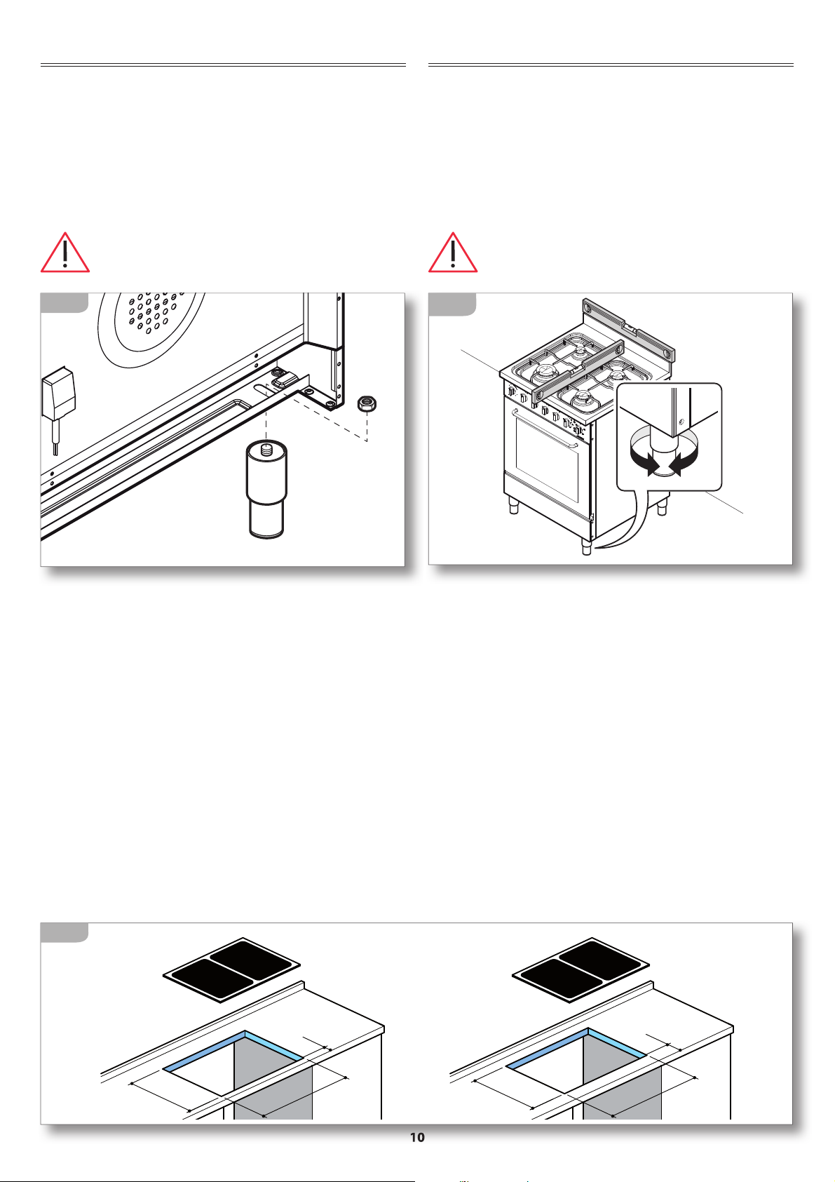
Distanza dalle pareti laterali e posteriori (Cucine combinate)
Le apparecchiature devono essere tenute ad una deter-
minata distanza dalle pareti (fig. 3).
NOTA: Qualora venga installata una cappa sopra il piano
cottura, consultare le istruzioni di montaggio della cappa
nelle quali è riportata la distanza corretta da rispettare.
AIR
AIR
AIR
2
INSTALLATION SITE CHOICE
Installation site characteristics
The appliances must be placed in suitable interior locations
with a maximum temperature of 25°C and maximum humid-
ity of 60%; the locations must satisfy the safety standards in
force in the country of use (protective isolating switch, earth-
ing system, equipotential system, etc.). The appliances are not
designed for outdoor use, to be exposed to the elements or bad
weather conditions.
The Combinata cookers must be assembled onto units made of
heat-resistant materials (120°C).
Installation locations must have continuous
air exchange to provide the air flow necessary for gas
combustion as specified in the standards in force UNI – CIG
7129 and 7131. Openings with an area of at least 100 cm2
must be constructed in such a way so that they cannot be
obstructed from neither the inside or the outside and they
must be positioned in proximity to the ground (fig. 2). Every
other ventilation type must be in accordance with specifica-
tions in the standard UNI – CIG 7129.
Fume discharge outlet
Gas appliances must release the combustion emissions
directly outside via flues, either by using extractor hoods or
electric fans (UNI – CIG 7129) (fig. 2) with sufficient power
to guarantee hourly air exchange at least 3 times the loca-
tion volume. It is to be noted that 2m3/h of air is necessary
for every kW of nominal thermal capacity (consult the data
plate for total thermal capacity).
Distance from side and back walls (
Combinata cookers
)
The appliances must be kept at a specified distance from
walls (fig. 3).
NOTE: If installing a range hood above the hob be sure
to follow the hood assembly instructions and the correct
mounting height contained therein.
min. 65 cm
min. 45 cm
A= 4 cm
B= 5 cm
A
B
3

10
POSIZIONAMENTO
Libera installazione CLASSE 1
Tra due mobili CLASSE 2/1
Combinata CLASSE 2/2
Alcuni modelli hanno la possibilità di montare dei
piedini di appoggio acquistabili separatamente;
ruotandoli è possibile regolare l’altezza della cucina
in base alle proprie esigenze (fig. 4).
Al termine dell’operazione verificare sempre
la perfetta planarità della cucina (fig. 5).
4
Cucine appoggio
Posizionare la cucina nel luogo scelto per l’installazione.
Se la cucina è posta su un piedistallo, si devono adot-
tare misure idonee per evitare che l’apparecchiatura
scivoli dal piedistallo stesso.
Cucine combinate (fig. 7)
1-2) Staccare il piano dalla cucina svitando le 4 viti la-
terali e le 8 viti che tengono in posizione i bruciatori.
3) Abbassare i traversini con le coppe agendo sulle
viti metriche.
4)
Posizionare la cucina
nel vano predisposto sotto al
piano
e riportare i traversini con le coppe all’altezza
originaria.
5) Rimontare il piano avvitando le 4 viti laterali e le 8
di fissaggio dei bruciatori.
6
POSITIONING
Freestanding CLASS 1
Between the forniture CLASS 2/1
Built-in CLASS 2/2
Some models may be fitted with support feet, which may
be purchased separately; by rotating them it is possible
to adjust the height of the cooker based upon specific
requirements (fig. 4).
At the end of this operation, always check the
perfect planarity of the cooker (fig. 5).
5
Freestanding cookers
Position the cooker within the selected installation site.
If the cooker is placed on a pedestal, suitable means
must be adopted to avoid that .the appliance slides off
the pedestal itself.
Combinata cookers (fig. 7)
1-2)Removethehobfromthecookerbyunscrewingthe4side
screws and the 8 screws which keep the burners in place.
3) Lower the cross-bars with holders by acting upon the
metric screws.
4)
Position the cooker
in the housing under the hob
and bring the cross-bars with holders back to their
original height.
5) Replace the hob by screwing the 4 side screws and 8
burner fixing screws.
top 30/40
top 30/40
400
560
35
585x420
480
560
60
585x500

11
8
Si consiglia di installare l’apparecchiatura a una
distanza da frigoriferi e congelatori tale che il calore
non pregiudichi il buon funzionamento di questi
ultimi (fig. 8).
It is recommended that you install the appliance far
from refrigerators and freezers so that the heat produced
does not compromise the good operation of these ap-
pliances (fig. 8).
7
x4
x4
x8
x8
1
2
4
6
7
5
3

12
CONNECTION TO THE POWER MAINS
Before making the connection, make certain
thatthevoltageandfrequency indicatedon the data
plate match those of the power supply system.
The oven is supplied with a 90 cm-long power cord
(H05V2V2-F) (fig. 9A).
Connect the cable directly to the electricity supply (fig.
9B), which must be made by an authorized person in ac-
cordance with current regulations in the country where
the appliance is installed. The installation must include
a means for disconnection from the supply having an
air gap contact separation in all active conductors that
allows complete disconnection in category III overvolt-
age condictions. The isolating switch should be sized
according to the load on the data label and should
comply with current regulations. If the supply cord is
damaged , it must be replaced by the manufacturer or
its service agent or a similarty qualified person in order
to avoid hazard.
The isolating switch must be located in a position
which is accessible even after the appliance is in-
stalled.
If the appliance is installed together with a hob, the
connection of the two appliances must be independ-
ent for electrical safety reasons.
The power cord must NOT:
- be crushed or rolled up;
- come into contact with any type of liquid, sharp or hot
objects or corrosive substances;
- reach,atanypoint,a temperaturewhichis50°Chigher
than the room temperature;
-
be replaced with a different type of cable
(see “TECHNICAL
DATA” on page 4)
or with a cable which is not up to
standard;
- be lengthened with extensions.
COLLEGAMENTO ELETTRICO
Prima dell’allacciamento accertarsi che la
tensione e la frequenza riportate sulla targhetta
caratteristiche corrispondano a quelle dell’impian-
to di alimentazione.
Il forno viene fornito già provvisto di un cavo di ali-
mentazione (H05V2V2-F) lungo 90 cm sul quale dovrà
essere installata una spina che sopporti i 16 A (fig. 9A).
In alternativa è possibile collegare il cavo direttamente
alla rete di distribuzione (fig. 9B): l’operazione deve
essere fatta da una persona autorizzata in conformi-
tà alla normativa vigente nel Paese di installazione.
L’impianto deve prevedere un dispositivo che assicuri
la disconnessione dalla rete con una distanza tra i
contatti che consenta la disconnessione completa
nelle condizioni della categoria di sovratensione III.
L’interruttore deve essere dimensionato in funzione
del carico sulla targhetta matricola e deve essere
conforme alle normative vigenti.
Se il cavo di alimentazione è danneggiato esso deve
essere sostituito dal Costruttore o dal suo servizio di
Assistenza Tecnica o comunque da una persona qua-
lificata similare, in modo da prevenire ogni rischio.
Sia la presa di corrente che l’interruttore onnipolare
devono essere a norma e collocati in posizione ac-
cessibile anche con l’apparecchiatura incassata.
Se l’apparecchiatura viene inserita in abbinamento
a un piano cottura, l’allacciamento delle due appa-
recchiature deve essere indipendente per motivi di
sicurezza elettrica.
Il cavo di alimentazione NON deve:
- essere schiacciato o arrotolato su se stesso;
- entrare in contatto con liquidi di qualsiasi tipo,
oggetti taglienti o caldi e sostanze corrosive;
- raggiungere in nessun punto una temperatura che
superi di 50°C la temperatura ambiente;
- essere sostituito con uno di tipo diverso (vedi “DATI
TECNICI” a pag. 4) o non a norma;
- essere allungato con prolunghe.
9
H05V2V2-F
3x1,5mm2
90 cm
16A
Mod.
Art.
N°
...V ...Hz ...Kw
Questo apparecchio deve essere installato conformemente
alle norme in vigore. Consultare il libretto istruzioni prima
di installare e usare l’apparecchio
F.lli Barazza S.r.l
MADE IN ITALY
9A
9B

13
SOSTITUZIONE DEL CAVO DI ALIMENTAZIONE
In caso di necessità, il cavo di alimentazio-
ne può essere sostituito con uno di tipo identico
(vedi “DATI TECNICI” a pag. 4) in ottemperanza
alle normative vigenti nel Paese di installazione.
Se l’apparecchiatura è già collegata,
staccarla dall’alimentazione elettrica e gas (se
prevista).
Per accedere ai collegamenti elettrici, togliere il coper-
chietto della morsettiera e far leva sul gancio (fig. 10).
Staccare il vecchio cavo dai morsetti e rimuoverlo;
collegare il nuovo cavo (unicamente di tipo H05V2V2-
F) nei rispettivi morsetti, N - L - Terra.
Bloccare il nuovo cavo con l’apposito passacavo
e richiudere la morsettiera riposizionando il suo
coperchio.
230V ~
cavo 3x4 mm²
400V ~ 2N
cavo 4x2.5 mm²
400V ~ 3N
cavo 5x2.5 mm²
cavo 3x1.5 mm²
1
2
3
N
L
N
T
4
1
2
3
N
N
T
L3
L1
L2
4
1
2
3
N
L
N
T
4
L
2
N
T
1
L
10
POWER CORD REPLACEMENT
If necessary, the power cord can be replaced
with an identical type
(see “TECHNICAL DATA” on
page 4) in compliance with current regulations
in the country where the appliance is installed.
If the appliance is already connected,
disconnect the electrical and gas power (where
present).
To access the electrical connections, remove the cover
from the terminal board and act on the hook (fig. 10).
Disconnect the old cord from the terminals and remove
it; connect the new cord (only the H05V2V2-F type) into
the respective terminals N - L - Earth.
Cover the new cord with the appropriate cord holder and
re-close the terminal, replacing its cover.
Le apparecchiature con piano elettrico sono predisposte per l’allacciamento ad una linea dome-
stica con tensione 220V monofase, è tuttavia possibile adattare l’apparecchiatura ad una diversa tensione
secondo quanto riportato nello schema della figura soprastante.
Appliances with electric hob are predisposed for connection to a domestic single-phase power supply of 220 V; you
can adapt the appliance to different a voltage value by following the instruction provided in the diagram of the figure above.

14
COLLEGAMENTO GAS
Prima dell’allacciamento accertarsi che
tutto l’impianto gas e i locali di installazione siano
in accordo con le normative vigenti nel Paese di
utilizzo (UNI-CIG 7129 e 7131).
- Accertarsi che la linea di alimentazione sia libera
da ostruzioni e di portata sufficiente ad assicurare
il corretto funzionamento dell’apparecchiatura.
- Accertarsi che sulla linea di alimentazione, in luogo
facilmente accessibile ed ispezionabile, sia inserito
un rubinetto di intercettazione del gas: esso dovrà
essere chiuso durante le operazioni di installazione
e manutenzione dell’apparecchiatura.
-
Verificare il tipo di gas con il quale sarà alimentata
l’apparecchiatura (Gas liquido G30/G31 oppure Me-
tano G20/25) e controllare che l‘ apparecchiatura sia
predisposto per quel tipo di alimentazione: in caso
contrario adattarlo seguendo le indicazioni riportate
nel par. “Adattamento ad altri tipi di gas”a pag. 17.
- Procedere all’allacciamento
(fig. 11)
: sulla rampa di
alimentazione“A”è montato un raccordo a gomito
“L” (filetto GJ ½”) che consente l’allacciamento alla
rete di distribuzione tramite un tubo rigido (norma
UNI-CIG 7129) oppure un tubo flessibile di acciaio
inox a parete continua (norma UNI-CIG 9891).
Il collegamento con il tubo rigido o flessibile deve
garantire la tenuta tramite la guarnizione “G2”.
Il raccordo di allacciamento “L” può essere
orientato allentando il dado “B” e poi, ese-
guita l’operazione di orientamento, bloccan-
do nuovamente il dado. La tenuta è garantita dalla
forma particolare della rampa e dalla guarnizione
interna.
11
GAS CONNECTION
Beforeconnecting theappliance,ensurethat
the gas system and the installation locations comply
with current regulations in the country where the
appliance is installed (UNI-CIG 7129 and 7131).
- Ensure that the supply line is not obstructed and has
sufficient power to ensure correct operation of the
appliance.
- Ensure that the supply line, which should be located
in an easily accessible and visible location, has a gas
shut-off valve: this should be closed during appliance
installation and maintenance operations.
-
Check the gas type which will power the appliance
(Liquid Gas G30/G31 or Methane G20/25) and ensure
that the appliance is compatible with this: in the case
where it is not compatible, adapt it as instructed in the
par. “Gas Conversion” on page 17.
- Proceed with connecting the appliance
(fig. 11)
:an L-
shaped rubber connector (thread GJ ½”) is assembled
to power ramp “A”; this ensures connection to the
distribution network via a solid pipe (standard UNI-
CIG 7129) or a flexible stainless steel pipe flush with
the wall (standard UNI-CIG 9891).
Connection to the solid or flexible pipe is guaranteed
by using sealant “G2” to secure attachment.
The ” L”-shaped connector can be positioned
by loosening the “B” nut and then, once posi-
tioned, re-tightening the nut. The specific form
of the ramp and the inner sealant guarantee attach-
ment.
A
L
(GJ ½)
B
G2
UNI-CIG 9891
UNI-CIG 7129

15
Qualora la pressione del gas sia poco stabile,
installare a monte dell’apparecchiatura un
regolatore di pressione del gas (se l’apparec-
chiatura deve funzionare a gas liquido (G30 o G31),
utilizzare esclusivamente un regolatore di pressio-
ne conforme alla norma UNI-CIG 7432 (30 mbar).
Ad installazione ultimata, controllare la
perfetta tenuta di tutti i raccordi utilizzando una
soluzione di acqua e sapone, NON fiamme libere!
Ad installazione ultimata, provate ad ac-
cendere tutti i bruciatori (consultare cap.“PIANO A
GAS - Uso dei bruciatori”) e verificate che la fiamma
sia regolare e stabile, eventualmente procedere
come indicato nel par. “Regolazione del minimo”
a pag. 16.
Ultimata la regolazione, si prega di istruire l’utente
sul corretto modo di utilizzo dell’apparecchiatura. Nel
caso in cui l’apparecchio non funzioni correttamente
dopo tutti i controlli effettuati, contattare il rivenditore
autorizzato di zona.
If the gas pressure is unstable and it runs on
liquid gas (G30 or G31), install, above the appli-
ance, a gas pressure regulator; only use a gas
pressure regulator which complies with the standard
UNI-CIG 7432 (30 mbar).
Before Leaving: Check all connections for
gas leaks with soap and water. DO NOT use a naked
flame for detecting leaks.
Before Leaving: Ignite all burners to ensure
correct operation of gas valves, burners and ignition
(see chapter “GAS HOB - Using the burners”). Turn
gas taps to low flame position and observe stability
of the flame, regulating the minimum if necessary
(see “Regulating the minimum” on page 16).
When satisfied with the hotplate, please instruct the
user on the correct method of operation. In case the
appliance fails to operate correctly after all checks have
been carried out, refer to the authorised service provider
in your area.
Problema: Soluzione
Il flusso del gas
sembra irregolare
• Controllare che il rubinetto
del gas sia aperto completa-
mente.
• Controllare che la rete di
allacciamento abbia portata
adeguata.
• Controllare che gli sparti-
fiamma e i bruciatori siano
posizionati correttamente e
siano liberi da ostruzioni.
• Controllare che gli ugelli
siano adatti al tipo di gas
utilizzato.
• Controllare la corretta taratu-
ra del regolatore di pressione
se presente.
• Controllare il tubo di alimen-
tazione gas (tubo ostruito,
tubo piegato/schiacciato,
tubo eccessivamente lungo,
tubo inadatto, ecc...).
Problem: Solution
The gasflowseems
irregular
• Check that the gas tap is fully
open.
• Checkthattheconnectionnet-
work has a sufficient supply.
• Check that the flame distribu-
tors and the burners are cor-
rectly positioned and that they
are not obstructed.
• Check that the nozzles are
suitable for the gas type used.
• Check that the pressure regu-
lator is correctly calibrated.
• Check the gas supply pipe
(check that the pipe is not
obstructed, folded/crushed,
too long, unsuitable, etc...).

16
REGOLAZIONE DEL MINIMO
Effettuare la regolazione del minimo su un
bruciatore alla volta.
- Accendere un bruciatore e portare la manopola
nella posizione di minimo .
- Sfilare la manopola corrispondente al bruciatore
acceso fino a toglierla del tutto (fig. 12 - part.1).
La vite di regolazione è localizzata lateralmente al
perno porta manopola e si raggiunge attraverso il
foro predisposto a tale scopo (fig. 12 - part.2).
- Agire sulla vite, girandola verso destra per dimi-
nuire la fiamma o verso sinistra per aumentarla,
fino ad ottenere il minimo che si desidera.
In caso di funzionamento a GPL Universale, la vite
di regolazione del minimo deve essere avvitata
completamente.
- Rimontare le manopole con la massima cura accer-
tandosi di averle posizionate correttamente.
Al termine della regolazione verificare che:
1) non vi siano fughe di gas e che il funzionamento
dei bruciatori risulti corretto utilizzando una solu-
zione di acqua e sapone, NON fiamme libere!
2) ruotando rapidamente le manopole dalla
posizione di massimo a quella di minimo, non si
abbiano spegnimenti dei bruciatori. Eventualmente
aumentare la portata dei minimi stessi agendo sulla
vite di regolazione.
1
2
12
REGULATING THE MINIMUM
Adjust the low flame on each burner one
at a time.
- Switch on a burner and bring the knob to the mini-
mum setting .
- Turn the knob regulating the relevant burner until the
knob completely comes away (fig. 12 - parts1).
The adjustment screw is located to the side of the knob
pivot hole and can be reached via a hole specifically
designed for this purpose (fig. 12 - parts 2).
- Turn the screw towards the right to decrease the
flame or towards the left to increase the flame, in
order to ascertain the desired idle setting.
If powered by Universal LPG, the adjustment screw
controlling the idle mode setting must be completely
screwed in.
- Replace the knobs with utmost care ensuring that you
have correctly positioned them.
Once you have completed the setting process,
check that:
1) there are no gas leaks and that the burners are
functioning correctly by using a mixture of water and
soap, NOT naked flames!
2) when rotating the knobs immediately from the
maximum to the minimum setting, that the burners
do not switch off. Increase the idle mode capacity
using the adjustment screws.

17
ADATTAMENTO AD ALTRI TIPI DI GAS
Togliere le griglie, gli spartifiamma e i bruciatori; con la
chiave in dotazione, togliere gli ugelli (fig. 13) e sosti-
tuirli con quelli allegati, rispettando scrupolosamente
il contrassegno e la “TABELLA UGELLI”.
Nel caso si proceda alla regolazione dell’apparecchio
per un tipo di gas diverso da quello previsto all’origine,
in allegato alla documentazione vengono fornite due
nuove etichette da apporre, a cura dell’installatore,
sulla targhetta matricola dell’apparecchiatura e sulla
garanzia al fine di rendere riconoscibile e documen-
tata la nuova regolazione.
13
GAS CONVERSION
Remove the racks, the flame distributors and the burners;
with the spanner provided, remove the nozzles (fig. 13)
and replace them with the provided nozzles, carefully
checking the identification mark and the “NOZZLE TA-
BLE”
.In the casewhereyou carryoutanapplianceregula-
tion operation for a gas type that differs from the above
mentioned, appended to the present documentation,
you will find two new stickers which must be attached to
both the appliance data plate and the Guarantee by the
person responsible for installation; the stickers recognise
and document the new regulation.
1
2
3

18
USO USAGE
AVVERTENZE DI SICUREZZA
PER UN USO CORRETTO E SICURO
Questa apparecchiatura è stata concepita e re-
alizzata esclusivamente per la cottura degli ali-
menti. Un uso diverso è considerato improprio
e quindi potenzialmente pericoloso per persone, anima-
li e cose. Inoltre potrebbe danneggiare irrimediabilmen-
te l’apparecchiatura: in questo caso il Costruttore non si
ritiene responsabile e non riconosce il diritto di Garanzia.
Chiudere sempre l’interruttore elettrico on-
nipolare prima di ogni operazione di pulizia
o in previsione di lunga inattività.
Assicurarsi che tutte le manopole siano a
“zero”(“OFF”- chiuso) al termine dell’utilizzo.
Se si dovesse notare una qualsiasi anomalia
non utilizzare l’apparecchiatura e contattare
un Centro di Assistenza autorizzato comuni-
cando i dati presenti nella targa matricola.
Questa apparecchiatura non è adatta all’uso da
parte di persone (inclusi i bambini) con difficoltà
fisiche, sensoriali o mentali o con mancanza di
esperienza e conoscenza, a meno che una persona respon-
sabile della loro sicurezza fornisca a queste una supervi-
sione o un’istruzione riguardo l’uso dell’apparecchiatura.
I bambini devono essere sorvegliati per assi-
curarsi che non giochino con l’apparecchia-
tura o con parti di essa.
Onde evitare pericolosi surriscaldamenti
dovuti ad un uso scorretto dell’apparecchia-
tura oppure ad un difetto dei componenti, il
forno è dotato di un termostato di sicurezza che, in
caso di funzionamento anomalo, stacca l’alimentazio-
ne elettrica. Il ripristino del termostato, in funzione
dell’abbassamento della temperatura del forno, è
automatico. Pertanto in caso di intervento del termo-
stato, per riutilizzarlo è sufficiente attendere il raffred-
damento del forno. In caso contrario, se l’intervento
è determinato da un difetto dei componenti, è neces-
sario far intervenire l’Assistenza tecnica.
SAFETY WARNINGS
FOR SAFE AND CORRECT USE
Thisappliancehasbeendesignedandmanufac-
turedexclusivelyforcookingfood. Anyotheruse
is considered improper and thus potentially
hazardousforpeople,animalsandproperty.Furthermore,
it may permanently damage the appliance: in this case,
the Manufacturer will not be held liable and the War-
ranty will be void.
Always disconnect the appliance from the
powersupplyusingtheomnipolarswitchbefore
carrying out any cleaning operations or when
the appliance will not be used for an extended period.
Make sure that the knobs are turned to “zero”
(“OFF”) when you finish to use the oven.
If you should note any anomalies, do not use
theappliancebut contactanauthorizedService
Centre and report the data indicated on the
data plate.
This appliance is not suited for use by persons
(including children) with physical, sensorial or
mental difficulties or lacking proper experience
and knowledge, unless supervised or instructed on the
use of the appliance by the person responsible for their
safety.
Children must be supervised to ensure that they
do not play with the appliance or parts of it.
To avoid dangerous overheating of the appli-
ance due to incorrect use or a defect in the
components, the oven is provided with a safety
thermostat that disconnects the power supply in case of
a malfunction. The thermostat starts working again
automatically when the temperature of the oven drops.
Therefore, if the thermostat is activated, it can be reused
after waiting for the oven to cool. Otherwise, if the acti-
vation occurred due to a component defect, contact our
technical service.

19
Non appoggiare pesi sulla porta aperta del forno
e non utilizzare la cavità di cottura per conser-
vare cibi umidi o oggetti di qualsiasi natura.
L’area nelle vicinanze della cavità del forno
potrebbe essere molto calda, prestare caute-
l
a nel posizionare in questo spazio prese di
corrente, altri elettrodomestici, cavi elettrici, tubazioni e
qualsiasi materiale sensibile al calore o infiammabile.
Non utilizzare prodotti spray nelle vicinaze di
questa apparecchiatura mentre è in funzione.
Non modificare questa apparecchiatura.
Pericolo di incendio!
Non utilizzare l’apparecchiatura come piano
di appoggio.
Pericolo di incendio!
Non posizionate mai oggetti sensibili al calore
o infiammabili (es. presine, tende, bottiglie di
alcoolici, ecc..) nelle vicinanze dell’apparecchiatura.
Se il piano cottura è corredato di coperchio è
indispensabile verificare sempre che le mano-
pole siano in posizione di chiuso e che i bru-
ciatori o le piastre si siano completamente raffreddati
prima di abbassare il coperchio.
Do not rest heavy objects on the oven’s open
door and do not use the cooking cavity to store
moist food or any other type of object.
The area near the oven cavity may become very
hot, so take precautions when positioning
power outlets, other household appliances,
electrical cables, hoses and any heat-sensitive or flam-
mable material in this area.
Do not spray aerosols in the vicinity of this ap-
pliance while it is in operation.
Do not modify this appliance.
Fire hazard!
Do not use the appliance as a support surface.
Fire hazard!
Never place heat-sensitive and flammable
objects (for example, oven gloves, curtains,
alcoholic containers, etc..) near the appliance.
In the instance where the hob features a cover,
you must always check that the knobs are in the
off position and that the burners or hot plates
are fully cooled down before lowering the cover.

20
PER LA COTTURA
Pericolo di scottature!
Durante il funzionamento e per alcuni minuti
dopo l’utilizzo, l’interno del forno ed alcune
parti esterne raggiungono temperature molto ele-
vate! Non entrare in contatto con queste parti senza
protezioni personali adeguate.
Prima dell’utilizzo verificare che gli spartifiam-
ma, i bruciatori e la griglia siano correttamente
posizionati.
In particolare controllare che la griglia appoggi corretta-
mente sull’apparecchiatura senza traballare.
Pericolo di scottature!
Non toccare gli elementi riscaldanti all’interno
del forno!
Pericolo di scottature!
Essendo accessibili elementi caldi quando in uso, per
evitare ustioni e scottature, i bambini devono essere
tenuti lontani.
Pericolo di incendio!
Non immettere nella cavità di cottura liquidi e/o
ingredienti alcolici durante il funzionamento.
Pericolo di incendio!
Non cucinate mai cibi alla fiamma.
Pericolo di incendio!
Nel caso di incendio del grasso o dell’olio
caldo non spegnere mai le fiamme con acqua
ma soffocarle con un canovaccio umido o similari e
avvisare tempestivamente i vigili del fuoco.
Sorvegliare l’apparecchiatura durante tutto il
suo funzionamento.
Per la cottura utilizzare soltanto recipienti, te-
glie e accessori espressamente concepiti per
tale utilizzo, realizzati in materiali resistenti alle
alte temperature e idonei al contatto con gli alimenti.
Lo sgocciolamento di alcune sostanze nella
cavità del forno (es. acidi della frutta) provocano
macchie che non è possibile rimuovere ma che
non pregiudicano le prestazioni dell’apparecchiatura.
Non versare liquidi freddi sulle pareti della cavi-
tà quando il forno è in funzione: lo sbalzo termi-
co potrebbe creare danni alle pareti interne.
FOR COOKING
Burn hazard!
During operation and for a few minutes after
use, the interior of the oven and some outer
parts reach very high temperatures! Do not touch these
parts without suitable personal protections.
Before using the appliance, check that the flame
distributors, the burners and the rack are cor-
rectly positioned. Check, in particular that the rack
rests correctly on the appliance without slipping or sliding.
Burn hazard!
Care should be taken to avoid touching heating
elements inside the oven.
Burn hazard!
Accessible parts will become hot when in use.
To avoid burns and scalds, children should be
kept away.
Fire hazard!
Do not introduce liquids and/or alcoholic ingre-
dients into the cooking cavity during operation.
Fire hazard!
Never cook food using naked flames.
Fire hazard!
In the case where fats or oils lead to fire, never
put out flames with water, instead suffocate the
flames using a moist dishcloth or a similar material and
immediately call the fire services.
Monitor the appliance during the entire time it
is in operation.
For the cooking, use only containers, pans and
accessories that have been specifically designed
for this use, made of high-temperature-resistant
materials and suitable for contact with foods.
The dripping of some substances in the oven
cavity (e.g., fruit acids) may cause stains which
cannot be removed, but the stains do not com-
promise the appliance’s performance.
Do not splash or pour cold liquids on the walls
of the cavity when the oven is operating: the
thermal stress may damage the interior walls.
This manual suits for next models
13
Table of contents
Other Barazza Cooker manuals
Popular Cooker manuals by other brands

Nesco
Nesco PC-6-25-30TPR use & care

Indesit
Indesit ID50G operating instructions

TEFAL
TEFAL Express IH7208 instructions

Bayou Classic
Bayou Classic KDS-1 SAFETY ALERTS, ASSEMBLY & OPERATING INSTRUCTIONS GENERAL MAINTENANCE & STORAGE

Omega
Omega OF914FX instruction manual

Indesit
Indesit KN3E11/EX operating instructions