barbas BOX 65 User manual
INSTALLATION INSTRUCTIONS &
MANUAL FOR ANNUAL MAINTENANCE
BOX 65
Barbas wishes you many cosy evenings with your new •re
This document is an essential part of your •re.
Read it carefully before installation and maintenance
of the gas •re and keep it in a safe place!
Serial number:
Production date:
Version number: 06 - 343929
Date: 03-06-2019

3
BOX 65
Installation instructions
1.
Unique identification code of the product-type
2.
Intended use or uses of the construction product, in
accordance with the applicable harmonised technical
specification, as foreseen by the manufacturer
3.
Name, registered trade name or registered trade mark
and contact address of the manufacturer as required
pursuant to Article 11(5)
4.
Where applicable, name and contact address of the
authorised representative whose mandate covers the
tasks specified in Article 12(2)
5.
System or systems of assessment and verification of
constancy of performance of the construction product
as set out in Annex V
6.
In case of the declaration of performance concerning a
construction product covered by a harmonised
standard
7. Declared performance
Fire safety
Distance to combustible materials Minimum distances, in mm
Rear = 300
Sides = 300
Ceiling = -
Front = 1800
Floor = 30
NPD
Thermal output
Energy efficiency
8.
Signed for and on behalf of the manufacturer by:
Danny Baijens, CEO
(Name and function)
Bladel; September 18, 2018 ………………………………………………………………………..
(place and date of issue) (Signature)
The performance of the product identified in point 1 is in conformity with the declared performance in point 7.
This declaration of performance is issued under the sole responsibility of the manufacturer identified in point 3.
Water heating output
- kW
Pass
Nominal heat output
8,7 kW
Room heating output
8,7 kW
Electrical safety
Pass
Cleanability
Pass
Maximum operating pressure
Not applicable
Flue gas temperature at nominal heat output
T = 323 °C
75 %
NPD
Pass
Risk of burning fuel falling out
Pass
Declaration of Performance
According to regulation (EU) 305/2011
No. 1.813.081-2 - CPR-2013/07/01
Box 65
Room heater without hot water supply
Barbas Bellfires BV; Hallenstraat 17; 5531 AB Bladel; The Netherlands
Not applicable
System 3
The notified laboratory SGS Nederland BV, No. 0608 performed the
determination of the product type on the basis of type testing under system 3
and issued test report EZKA/2016-07/00008-1
Harmonized technical specification
EN13240:2001/A2:2004/AC:2007
Essential characteristics
Performance
CO = 0.08 vol%
Emission of combustion products
Mechanical resistance (to carry a chimney/flue)
Surface temperature
Release of dangerous substances
Pass

4
BOX 65
Installation instructions
1.
Unique identification code of the product-type
2.
Intended use or uses of the construction product, in
accordance with the applicable harmonised technical
specification, as foreseen by the manufacturer
3.
Name, registered trade name or registered trade mark
and contact address of the manufacturer as required
pursuant to Article 11(5)
4.
Where applicable, name and contact address of the
authorised representative whose mandate covers the
tasks specified in Article 12(2)
5.
System or systems of assessment and verification of
constancy of performance of the construction product
as set out in Annex V
6.
In case of the declaration of performance concerning a
construction product covered by a harmonised
standard
7. Declared performance
Fire safety
Distance to combustible materials Minimum distances, in mm
Rear = 300
Sides = 300
Ceiling = -
Front = 1300
Floor = -
NPD
Thermal output
Energy efficiency
8.
Signed for and on behalf of the manufacturer by:
Danny Baijens, CEO
(Name and function)
Bladel; September 18, 2018 ………………………………………………………………………..
(place and date of issue) (Signature)
The performance of the product identified in point 1 is in conformity with the declared performance in point 7.
This declaration of performance is issued under the sole responsibility of the manufacturer identified in point 3.
Water heating output
- kW
Pass
Nominal heat output
8,7 kW
Room heating output
8,7 kW
Electrical safety
Pass
Cleanability
Pass
Maximum operating pressure
Not applicable
Flue gas temperature at nominal heat output
T = 323 °C
75 %
NPD
Pass
Risk of burning fuel falling out
Pass
Declaration of Performance
According to regulation (EU) 305/2011
No. 1.813.082-2 - CPR-2013/07/01
Box 65 with woodlog storage module
Room heater without hot water supply
Barbas Bellfires BV; Hallenstraat 17; 5531 AB Bladel; The Netherlands
Not applicable
System 3
The notified laboratory SGS Nederland BV, No. 0608 performed the
determination of the product type on the basis of type testing under system 3
and issued test report EZKA/2016-07/00008-1
Harmonized technical specification
EN13240:2001/A2:2004/AC:2007
Essential characteristics
Performance
CO = 0.08 vol%
Emission of combustion products
Mechanical resistance (to carry a chimney/flue)
Surface temperature
Release of dangerous substances
Pass

5
BOX 65
Installation instructions
TABLE OF CONTENTS
Page
1 Introduction
1.1 General ......................................................................................
.........
. 7
1.2 Safety and installation instructions .
.........................................
....
.......
. 8
2 Placing
2.1 Included ...........................................................
.............................
....... 10
2.2 Preparation for positioning .....................................................
..
.
.
..
.
...
.... 10
2.3 Accessories ..................................
.............................
...........
..
....
......
... 11
3 Installation
3.1 Instructions .........................................
.................................................
. 13
3.2 Flue gas channel .
..........
.....................................
........................
........
.. 13
3.3 Fitting ...................................................................................
..............
.. 14
3.4 Preparation / Function check ....................
..........
...................
........
...... 16
4 Operation .................................................................................................... 18
5 Annual maintenance ................................................................................... 20
6 Replacement parts
.
...............
.....................................
.................
..
.....
.....
.
...
22
7 Dimensions .....................................................................................
..
....
...
... 28
8 Technical data ...........................
..........
..........................................
...
........... 30
9 Warranty terms ....
......................................
....................................
.......
...... 31

6
BOX 65
Installation instructions

7
BOX 65
Installation instructions
1 INTRODUCTION
1.1 GENERAL
The appliance must be positioned and connected by a Barbas dealer/specialist in
accordance with the following installation instructions, nationally and locally applicable
regulations. This manual contains directions for both positioning the appliance and for
its environmentally-friendly use. It also contains technical data for the appliance, parts
information and directions in the event of problems.
This appliance is recommended as suitable for use in smoke control areas when
burning wood logs. The appliance, when sold into the UK market, include a factory-
installed modified air slider to ensure compliance with smoke emission requirements
within smoke control areas.
Study this manual carefully before using the fireplace. We recommend you keep this
manual in a safe place for reference purposes.
The pictures in this Installation Instructions are made from a variant of this appliance.
Although the dimensions of the appliance on the pictures may differ from reality, the
actions and instructions shown are fully valid for the appliance described here.
See the “Instructions for use” for the operation of the appliance
The “Instructions for use” is provided separately by the appliance.
“The Clean Air Act 1993 and Smoke Control Areas”
Under the Clean Air Act local authorities may declare the whole or part of the district of
the authority to be a smoke control area. It is an offence to emit smoke from a chimney
of a building, from a furnace or from any fi xed boiler if located in a designated smoke
control area. It is also an offence to acquire an “unauthorised fuel” for use within a
smoke control area unless it is used in an “exempt” appliance (“exempted” from the
controls which generally apply in the smoke control area).
In England appliances are exempted by publication on a list by the Secretary of State
in accordance with changes made to sections 20 and 21 of the Clean Air Act 1993 by
section 15 of the Deregulation Act 2015.
In Scotland appliances are exempted by publication on a list by Scottish Ministers under
section 50 of the Regulatory Reform (Scotland) Act 2014.
In Northern Ireland appliances are exempted by publication on a list by the Department
of Agriculture, Environment and Rural Affairs under Section 16 of the Environmental
Better regulation Act (Northern Ireland) 2016.
In Wales appliances are exempted by regulations made by Welsh Ministers.
Further information on the requirements of the Clean Air Act can be found here:
https://www.gov.uk/smoke-control-area-rules.
Your local authority is responsible for implementing the Clean Air Act 1993 including
designation and supervision of smoke control areas and you can contact them for
details of Clean Air Act requirements.

8
BOX 65
Installation instructions
1.2 SAFETY AND INSTALLATION INSTRUCTIONS
• Do not place flammable objects within 110 cm of the radiation area of the appliance.
Pay special attention to furnishings and ornaments around the appliance.
• To ensure safe operation, the following minimum distances must be maintained
between the appliance and any combustible material at the side, rear and top of the
appliance (temperature ≤ 80 °C).
in respect of side wall: Distance minimal 30 cm
in respect of rear wall: Distance minimal 30 cm
in respect of top: Distance minimal 50 cm.
• The minimum distance between the side, rear and top of the appliance and a wall of
non-combustible material must be at least 5 cm.
• When placed on a combustible floor, a hearth of non-combustible material must be
placed underneath the appliance. This hearth shall extend at least 20 cm on each
side of the appliance. If the appliance is placed without the optional wood log storage
module, the hearth shall have a minimum thickness of 3 cm.
• When you use your appliance, the exterior will become hot. Always wear the glove
or use the accessories supplied when filling etc.
Protect yourself and others (especially children!) from burns. Do not leave children
unattended when the appliance is burning.
• Watch your clothing. Synthetic clothing in particular can easily catch fire and burn
intensely.
• Do not approach the appliance with flammable materials or liquids. Any work with
solvents, adhesives etc. in the space heated by the appliance can be very
dangerous.
• It is not allowed to connect the appliance to a flue which is already connected to
another appliance.
•
Check
the chimney. Cracks in the chimney may
not only lead to damp, st
aining
of walls and leaking of smoke, they can also impair the carrying off of smoke
.
• Prevent your chimney being soiled from above (birds’ nests etc.) by fitting a suitable
cap to the chimney pot.
• The appliance must be placed on a sufficient solid floor that can bear the weight of
the appliance. (see chapter 8 “Technical data”).
• Avoid chimney fires! Have your chimney swept at least once per year - more often
if you use your fire a lot. Prevent excessive deposits of soot inside the chimney by
not burning freshly-cut wood. Instead, burn clean, dry chopped wood.

9
BOX 65
Installation instructions
• Follow the instructions issued by your local fire brigade.
The appliance can be taken in operation if national and local regulations are satisfied.
The required constructive adaptations should be satisfied as well.
• It is essential that the appliance, the flue and combustion air supply are cleaned and
inspected annually by a Barbas dealer/specialist.
The safe operation of the appliance will thus remain guaranteed.
• The appliance is suitable and approved for periodical use.
• The appliance may only be set up if the appliance and location meets the
- national and local installation regulations;
- local fire brigade regulations and required architectural provisions.
• Ensure that the room in which the appliance is situated has adequate ventilation.
• Wood and wood briquettes may be stoked in the appliance.
Do not use any coal and liquid fuels or fuel gel in the appliance. The appliance is
not intended for use of this fuels and can be dangerous and lead to damage to your
health and may seriously damage the appliance.
• Never use the appliance to burn rubbish.
• Please read all instructions / stickers on and around the appliance.
• Read the “Directions for use” before using the appliance for the first time. When you
first fire up your appliance, there are a number of extra points you should take into
account.
• In transit, some parts of the appliance may have moved from their original place.
Check that the door opens and closes, the baffle plates are fitted correctly to the
brackets at the top of the appliance and the heat-resistant panels are fixed to the
walls. Check if there are no foreign objects in the appliance.
• Avoid over-loading (white burning glow), caused, for example, by lengthy burning
with primary air (combustion air supply slider all the way to “ +”) or by burning too
much wood in one go. The appliance can then become over-heated.
• Ask for the local building regulations, before commensing the installation of the
appliance.

10
BOX 65
Installation instructions
Set documentation • Directions for use
• Installation instructions
Attributes • Glove (Heat resistant up to max. 95°C)
• Operating hook / Poker
2 LOCATION
2.1 INCLUDED
2.2 ACCESSORIES
The following accessories can be supplied by your dealer:
N.B. If any part is missing, please contact your dealer.
Thick-walled (2 mm) steel chimney system Ø150 mm:
Part no Description
343122 Pipe 1950 mm with reduction
339213 Pipe 500 mm with reduction
339212 Pipe 1000 mm with reduction
339216 Elbow 90°
339215 Elbow 45°
339214 Elbow 30°
302226 Support sleeve (L= 190 mm) double-walled
339218 Rosette
11
BOX 65
Installation instructions
2.3 PREPARATION FOR POSITIONING
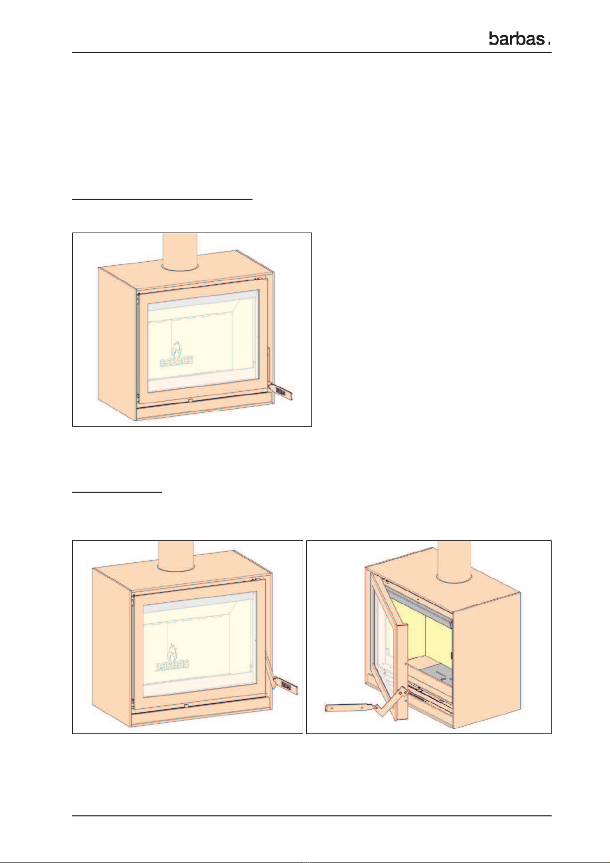
Check all functions of the appliance before fitting.
• Check the opening and closing operation of the door.
Turn the handle all the way down:
Door is locked.
Handle forwards:
The door releases from its lock and can be opened forwards.
For this, use the operating hook supplied.

12
BOX 65
Installation instructions
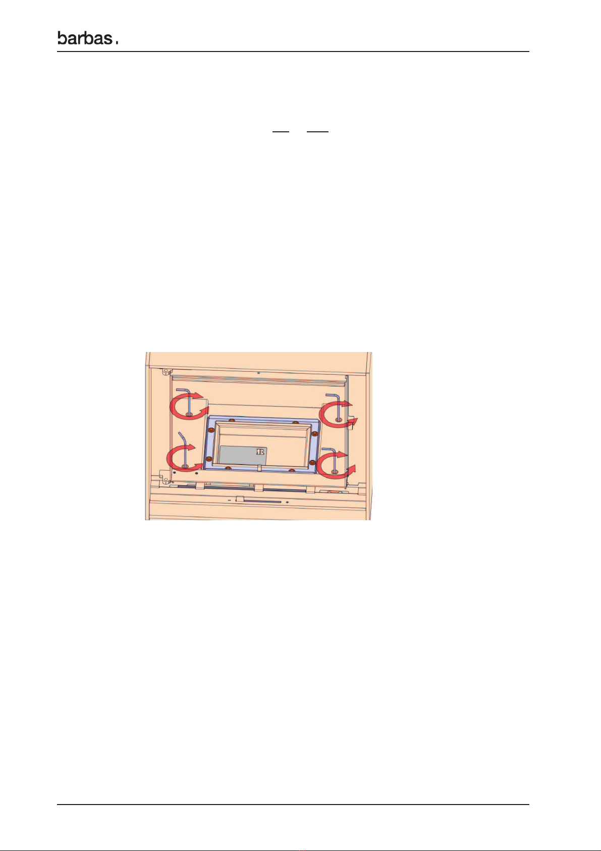
• Check whether the 2 baffle
plates are located correctly in the supports.
• Check the operation of the slider for the regulation of the combustion air intake
(middle below the window).
• Check whether the ashtray is completely empty.
• Report any defects immediately to your dealer.
• Remove enclosed documents and components from the appliance.
• Have the suitability of the area in which the appliance is to be placed (and the
chimney) approved by a specialist. The stove must have its own chimney,
constructed in compliance with current legislation.

13
BOX 65
Installation instructions
3 INSTALLATION INSTRUCTIONS
3.1 FITTING INSTRUCTIONS
When fitting the stove, local and/or national regulations relating to fire safety must be
followed. In case of doubt, consult the fire safety department of the local fire brigade,
particularly if the stove is to be fitted in a home with walls and/or floors containing
flammable material.
Position the appliance sufficiently far away from the wall behind it, according to the data
from chapter 1.2. If the walls are not fire-proof, the distance should be such that the wall
in question cannot become hotter than 80°C, even when the stove is stoked up to high
temperatures. In case of doubt, insert a fire-proof protection shield.
The floor on which the appliance is placed must have sufficient bearing power.
The connection of several appliances to a single flue/chimney is not allowed.
3.2 CHIMNEY
Be sure that existing chimneys are completely air-tight and in good condition. In terms
of dimensions, the chimney must have a diameter of at least 150 mm for the entire
length (including the chimney pot).
Ensure that the chimney is fitted with an appropriate cap to avoid rain and dirt getting in
(as well as bird’s nests).
The draught flowing through the chimney determines how well your stove will burn
(minimum draught 0.12 mbar = 12 Pa; recommended draught 0.15 mbar: = 15 Pa).
In the event of problems, a solution may be a different chimney cap, if necessary one
with a chimney fan. Contact a specialist if you have any doubts about any of the above
points.
If your chimney is unsuitable, or if your home does not have a chimney, we recommend
the use of double-walled stainless steel chimney sections. Chimneys must comply with
the prevailing building regulations. Make sure the building is carried out by a specialist.
When purchasing such chimneys, be sure to check if a casing is required.
Important:
• Chimneys must be free-standing, i.e. they must not rest on the appliance itself.
• Any pipe connections that are not insulated must also be fully insulated.
• Flammable material must be kept clear (outside the casing/insulation zone) of all
through-feeds in the floor or wall (remember the roof decking).
• The chimney opening must be at least 5 metres above the top of the door opening of
your appliance.
• The chimney must protrude at least 40 cm above the apex of a sloping roof and at
least 1 metre above a flat roof. In short, the chimney must always end in an area with
a negative air pressure. Contact your local chimney sweep for the exact dimensions
of the chimney opening.

14
BOX 65
Installation instructions
Between the stove and chimney, use thick-walled smoke piping (Steel, ≥2 mm). See
Chapter 2.2.
The first pipe connected to the appliance must have a diameter of 130 mm at both ends.
This will prevent any condensation from the chimney running over the external end
of the pipe. Connect the pipes to the existing chimney (ceiling) using a sliding sleeve
(niche pipe). Check all connections for air-tightness.
If there is too much draught running through your chimney (e.g. if the chimney is long
and straight in a tall building), it may be possible to insert a chimney valve in the pipe
near the appliance. Before doing this, be sure to obtain sound advice from a specialist.
Do not make any horizontal connections. Deposits and soot will accumulate here
(unless it is a short horizontal connection directly behind the stove).
Avoid bends at all costs. The maximum deviation from the perpendicular is 45°.
The chimney calculation, as in Germany, is made according to DIN 4705 parts 1 and 2.
The mass flow and exhaust temperature of the stove
The mass flow and exhaust temperature of the stove are shown in chapter 8;
Technical Data. These values are important to consider when assessing the dimensions
of the flue to which the stove is to be connected.
Cleaning the chimney/flue
Make sure your chimney/flue is cleaned at least once a year by a recognized chimney
sweep.
If the chimney has a chimney valve, the free opening in the chimney valve flap must
measure at least 12% of the surface.
3.3 COMBUSTION AIR
Combustion air is needed to keep the combustion going by drawing in air from the
room, of directly from outside, due to the natural draught of the chimney.
On delivery, the appliance is prepared for a combustion air supply from the living room
or a combustion air supply directly from the outside, through the underside or through
the back of the appliance.
• Combustion air from the living-room:
The air inlet openings are located under the operating flap. When using the
appliance, please ensure there is a sufficient supply of fresh air: use a grate with a
minimum net opening in the outer wall of 150 cm2.
Make sure that the ventilation supply is open; this is particularly important with
today’s airtight dwellings.

15
BOX 65
Installation instructions
If the dwelling has mechanical ventilation that creates under pressure in the room
where the appliance is located, it is necessary to fit a flue gas fan.
The type of flue gas fan is dependent on the capacity of the mechanical ventilation
system. Always consult your fitter about this.
In dwellings with an operating extractor hood, this should be turned to the lowest
setting or turned off altogether. If the extractor hood remains in use, additional
ventilation must be provided in compensation. This will not only avoid poor
combustion, but will also prevent flue gases being sucked from the appliance into
the room.
Should creating an extra ventilation opening prove insufficient, it is then necessary
to fit a flue gas fan.
• Combustion air directly from outside:
The appliance now has a completely closed combustion syst
em
, which allows it to
operate independently of the surrounding air in the room where the appliance is
located.
The combustion air supply can be connected to the back or the underside of the
appliance. To do this, use combustion air connection Ø125 mm (exterior) for the back
or underside. Install a fixed or flexible pipe of Ø125 mm in the wall/floor between this
air supply connection and outside air supply inlet. We recommend that this pipe is
fitted with a sealing valve in order to prevent condensation in the appliance when it
is not in use.
16
BOX 65
Installation instructions
3.4 FITTING THE STOVE
3.4.1 Positioning
The appliance can make use of either a top or rear connection Ø150 mm for the flue
(chimney).
This connection is intended for steel stovepipes, double/single-skinned stainless steel
(insulated) flues or double/single-skinned flexible stainless steel flues.
Situate the appliance in such a way that the flue gas outlet is precisely in line under the
chimney connection (niche pipe) in the ceiling (top connection) or with the chimney
connection (niche pipe) in the wall (rear connection).
Level off the appliance using the adjustable feet (not for Box with wood log storage
module"). The adjustable feet are accessible from the combustion chamber. To do this
remove the steel sheets on both sides of the grate. Using an Allen key no. 4 to set the
adjustable feet on the correct height.
If the appliance is placed on a natural stone platform, the following must be considered:
- Place the appliance approximately 3 mm above the platform by means of the
adjustable feet.
- The platform must have minimum thickness of 3 cm.
- The platform must support the weight of the appliance directly underneath it.
- Ask your natural stone dealer for additional advice regarding the speci#c type of
stone in combination with the appliance.
When placed on a surface of combustible material, an insulating plate of at least 3 cm
thickness between the appliance and the combustible material must be placed.
17
BOX 65
Installation instructions
3.4.2 Connecting to the chimney
Ceiling connection:
Insert a pipe into the sliding sleeve (niche pipe) to the ceiling as deep as possible.
Position a chimney pipe on the top plate and mark off where the top pipe should be
shortened.
Shorten the top pipe and insert it, once more, as deep as possible into the sliding sleeve
in the ceiling. Position the lower pipe over the sealing washer. Now pull the top pipe
down and over the bottom pipe.
Wall connection:
Determine the length of pipe required and push this as far as possible into the sliding
sleeve before the appliance is placed.
Once the appliance is placed, you can pull the pipe from the sliding sleeve and slide it
over the connection ring on the appliance.
Any seams in the flue gas outlet (pipes) joints should be
sealed with a heat-resistant kit that remains elastic or
with a glass-fibre cord.

18
BOX 65
Installation instructions
4 OPERATION
Figure 1: Operation Box
1 Handle
2 Ceramic heat-proof glass
3 Grate
4 Ashtray
5 Combustion air-supply slider (Combined operation for the primary, secondary and
tertiary combustion air-supply)
6 Inlet opening (2x) combustion air from living-room, if a direct outside air supply is not
connected. This will be determined when the appliance is installed.
Do not EVER close open inlet openings.
7 External connection combustion air supply (not pictured: possible at the bottom)

19
BOX 65
Installation instructions
Figure 2: Operation Box with wood log store module
1 Handle
2 Ceramic heat-proof glass
3 Grate
4 Ashtray
5 Combustion air-supply slider (Combined operation for the primary, secondary and
tertiary combustion air-supply)
6 Inlet opening (2x) combustion air from living-room, if a direct outside air supply is not
connected. This will be determined when the appliance is installed.
Do not EVER close open inlet openings.
7 External connection combustion air supply (not pictured: possible at the bottom)
20
BOX 65
Installation instructions
5 ANNUAL MAINTENANCE
Start with maintence 24 hours after the last burning period.
Recommended order for yearly maintenance:
•Inside the appliance:
• Check the door seals. If necessary, replace the seals.
• Temporarily remove the door, by opening it competely and lifting it upwards.
• Remove the complete interior of the appliance and carefully clean all parts with
a hand brush.
Emptying the ashtray.
• Clean the glass on the inside of the door with glass spray or ceramic hob
cleaner.
• If the glass is broken or cracked, it must be immediately replaced before
operating the appliance again.
Broken ceramic heat-resistant glass
may not be thrown away in a glass
container, but must be included in
normal household waste.
• Check the grate and all interior plates on cracks.
If necessary, replace the parts.
‚Chimney/flue channel:
• Sweep and inspect chimney. Check for cracks, loose parts, flue gas leakage
and overall condition of the chimney.
When in doubt use an inspection camera "
ƒCombustion air supply appliance:
• Check the combustion air supply route from the outside up to the appliance.
• Clean the combustion air supply inlet openings.
It is essential that the appliance, the chimney and the
combustion air supply are cleaned and inspected
annually, by a Barbas-dealer/expert.
The safe operation of the appliance will thus remain
guaranteed.
Table of contents
Other barbas Wood Stove manuals

barbas
barbas BOX30 75 User manual

barbas
barbas BOX 52 User manual

barbas
barbas BOX 40 User manual

barbas
barbas BOX 45 User manual

barbas
barbas UNIVERSAL-6 70 Specification sheet

barbas
barbas BOX 67 User manual

barbas
barbas BOX 75 User manual

barbas
barbas BOX 70 User manual

barbas
barbas CUATRO-3 75 User manual

barbas
barbas UNILUX-6 70 Specification sheet
Popular Wood Stove manuals by other brands


RAIS
RAIS attika NEXO 100 GAS installation guide

WoodPro
WoodPro WS-TS-1500 owner's manual

Contura
Contura C 586W installation instructions

Palazzetti
Palazzetti EVA GENERAL INFORMATION - WARNINGS - INSTALLATION - MAINTENANCE

Lopi
Lopi 1250 Republic owner's manual

Panadero
Panadero CAPRI 3V Usage and maintenance instructions