Manual 2100-665G
Page 2 of 28
FIGURES AND TABLES
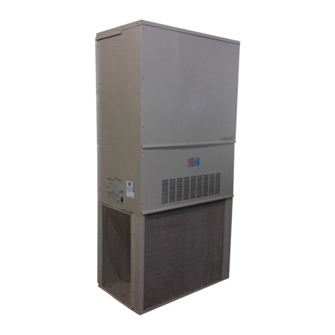
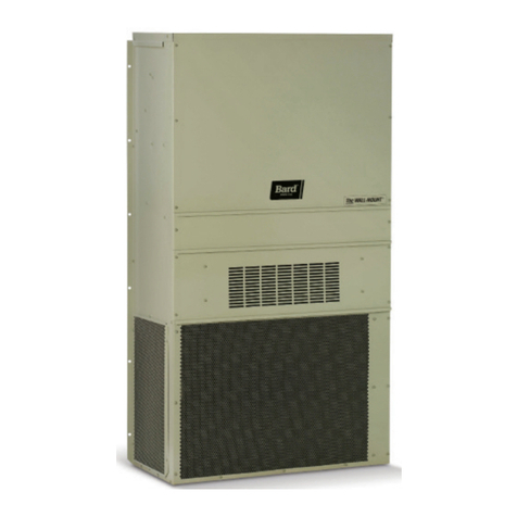
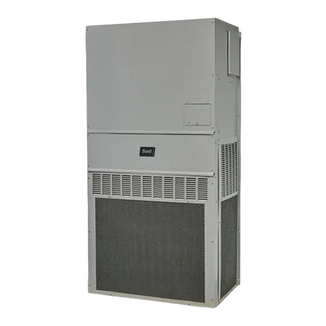
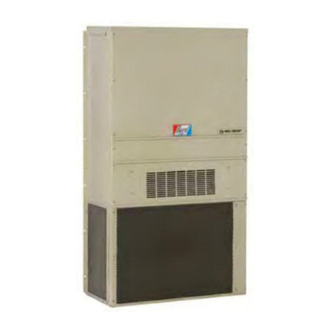
Figure 1 MULTI-TEC Wall-Mount Unit Model
Nomenclature ........................................3
Figure 2 TEC-EYE Display and Interface ................6
Figure 3 TEC-EYE Connection to Unit Control ........6
Figure 4 Quick Menu Icons...................................7
Figure 5 Cooling and Heating Setpoints .................8
Figure 6 Last 24 Hour Tracking.............................8
Figure 7 Last 24 Hour Tracking.............................8
Figure 8 Software Version Information ...................8
Figure 9 Alarm Log Screen Breakdown ..................8
Figure 10 Unit Configuration ..................................9
Figure 11 Executing Run Test.................................9
Figure 12 Alarm Screen Breakdown.......................11
Figure 13 Clearing Alarms ....................................11
Figure 14 Clearing Alarm Logs..............................12
Figure 15 Adjusting Mixed Air Alarm Values...........12
Figure 16 Adjusting Damper Alarm Values .............13
Figure 17 Adjusting Freeze Alarm Values ...............13
General Information ...........................................3
Free Cooling Unit System.......................................3
Wall-Mount Air Conditioner Units............................3
General ................................................................3
Shipping Damage..................................................4
Additional Publications..........................................4
Using the TEC-EYETM ...........................................6
TEC-EYE Hand-Held Diagnostic Tool .......................6
TEC-EYE Menu Structure......................... 7
TEC-EYE Acronyms ................................. 7
Status Screen......................................... 7
Quick Menu............................................ 8
Setpoints ......................................... 8
Information ...................................... 8
Data (Alarm) Log............................... 8
Menu Screens and Password Levels .......... 9
Addressing Wall-Mount Units ................... 9
Setting Unit Zone ................................... 9
Additional Features ................................. 9
Model/Serial Number Retain Feature .. 9
Time/Date/Timezone Sync .................. 9
Executing a Run Test............................... 9
Parameter Description ..................... 10
Changing Free Cooling Type ................... 10
Alarms.................................................................11
Acknowledging/Clearing Alarms.................... 11
Clearing Alarms .................................... 11
Clearing Alarm Logs .............................. 12
Alarm Adjustment....................................... 12
Mixed Air Alarm.................................... 12
Refrigerant Low Pressure ....................... 12
Refrigerant High Pressure ...................... 13
Economizer Damper .............................. 13
Freezestat ............................................ 13
Control Operation .............................................14
On/Off Control ............................................ 14
Fan Control ................................................ 14
CONTENTS
Temperature Control.................................... 14
Cooling Sequence – Economizer Available
.. 14
Cooling Sequence –
Economizer Not Available ...................... 14
Heating Sequence................................. 15
Free Cooling............................................... 16
Economizer Disable............................... 16
Economizer Enable ............................... 16
None ............................................. 16
Drybulb Only .................................. 16
Temperature and Humidity (Default) . 16
Enthalpy ........................................ 16
Economizer Modulation ......................... 16
Compressor ................................................ 17
Enable................................................. 17
Delays and Run Time............................. 17
Electric Reheat Dehumidification ................. 17
Mechanical Dehumidification....................... 18
General Refrigerant Information...................19
General ..................................................... 19
Topping Off System Charge.......................... 19
Safety Practices.......................................... 19
R410A Refrigerant Charge........................... 19
Componentry .....................................................21
High Pressure Switch .................................. 21
Three Phase Scroll Compressor
Start Up Information ................................... 21
Phase Monitor ............................................ 21
Condenser Fan Operation............................. 21
Low Ambient Control................................... 21
Compressor Control Module ......................... 22
Pressure Service Ports................................. 23
Outdoor Fan Motor...................................... 23
Maintenance and Troubleshooting ...............26
Standard Maintenance Procedures ............... 26
Removal of Fan Shroud ............................... 26
Troubleshooting Nidec SelecTech ECM Motors
.. 27
Figure 18 Wall-Mount Unit Cooling Staging............14
Figure 19 Adjusting Cooling Differential Values ......15
Figure 20 Adjusting Heating Differential Values......15
Figure 21 Wall-Mount Unit Heating Staging ...........15
Figure 22 Economizer A4 Screen ..........................16
Figure 23 Economizer A5 Screen ..........................16
Figure 24 Adjusting Damper Modulation Value .......17
Figure 25 Dehumidification Control.......................17
Figure 26 Wall-Mount Unit Control Board ..............18
Figure 27 8201-164 Compressor Control Module ...22
Figure 28 Fan Blade Setting.................................23
Figure 29 Motor Connections................................27
Figure 30 Motor Connections................................28
Table 1 Wall-Mount Unit Status Messages ............7
Table 2 LC1000/TEC-EYE Passwords (Defaults) ....9
Table 3 Wall-Mount Unit Alarm Index.................11
Table 4 Cooling Pressures .................................20
Table 5A Optional Accessories – Right Hand.........24
Table 5B Optional Accessories – Left Hand...........25

