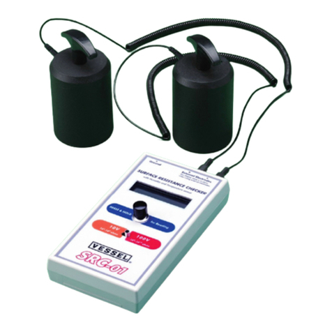
barfield 2471F Operator's manual

2471F MEGOHMMETER
USER INSTRUCTION MANUAL
BARFIELD M/N 2471F
56-101-00220-B
September 23, 2008
________________________________________
BARFIELD, INC.
Corporate Headquarters
4101 Northwest 29th Street
Miami, Florida 33142
www.barfieldinc.com
Email: gsesales@barfieldinc.com
To buy, sell or trade in this product click on the link below:
http://www.avionteq.com/Barfield-2471F-MEGOHMMETER-PN-101-00220.aspx
www.avionteq.com


2471F INSTRUCTION MANUAL
56-101-00220-B Blank
09 /23/08 Page ii
This page intentionally left blank.

2471F INSTRUCTION MANUAL
56-101-00220-B Blank
09 /23/08 Page iii
This page intentionally left blank.

2471F INSTRUCTION MANUAL
56-101-00220-B Contact
09 /23/08 Page iv
CONTACT INFORMATION
Users are requested to notify the manufacturer of any discrepancy, omission, or error
found in this manual. Inquiries should include specific questions and reference the
publication title, number, chapter, page, figure, paragraph, and effective date.
Please send comments to:
TECHNICAL CUSTOMER SUPPORT - GSTE
BARFIELD, INC.
P.O. BOX 025367
MIAMI, FL 33102-5367
USA
Telephone (305) 894-5400
(800) 321-1039
Fax (305) 894-5401

2471F INSTRUCTION MANUAL
56-101-00220-B Blank
09 /23/08 Page v
This page intentionally left blank.

2471F INSTRUCTION MANUAL
56-101-00220-B Attention
09 /23/08 Page vi
ATTENTION
Although every effort has been made to provide the end user of this equipment with the most
current and accurate information, it may be necessary to revise this manual in the future. Please
be sure to complete and return a Revision Request Form to Barfield revision services and visit
the company website, http://barfieldinc.com/, for publication updates.
Additionally, Barfield MUST have your name and address on file as a registered user of this
equipment to ensure validation of the warranty. Please complete the OWNER WARRANTY
REGISTRATION card promptly. This card ensures validation of the warranty.
Please send to:
Barfield, Inc.
P.O. Box 025367
Miami, FL 33102-5367
USA

2471F INSTRUCTION MANUAL
56-101-00220-B Blank
09 /23/08 Page vii
This page intentionally left blank.

2471F INSTRUCTION MANUAL
56-101-00220-B Rev.
09 /23/08 Page viii
REVISION RECORD
REV. ECO # REV. DATE DESCRIPTION OF CHANGE
A N / A June 1986 Initial Release.
B 260-00729 Sep /23 /2008 Company logo and contact information was updated.
Chapters were reorganized.

2471F INSTRUCTION MANUAL
56-101-00220-B Blank
09 /23/08 Page ix
This page intentionally left blank.

2471F INSTRUCTION MANUAL
56-101-00220-B Maint.
09 /23/08 Page x
LIST OF APPROVED REPAIR FACILITIES
The manufacturer of this equipment does not recommend the user to attempt any maintenance
or repair. In case of malfunction, contact the manufacturer, to obtain the list of approved repair
facilities worldwide, ensuring that this equipment will be serviced using proper procedures and
certified instruments. A Return Maintenance Authorization (RMA) number will be assigned dur-
ing this call, to keep track of the shipment and the service.
BARFIELD PRODUCT SUPPORT
DIVISION
Shipping Address:
Telephone (305) 894-5400
(800) 321-1039
Fax (305) 894-5401
Barfield, Inc.
4101 NW 29th Street
Miami, Florida 33142
USA
Mailing Address:
Barfield, Inc.
P.O. Box 025367
Miami, FL 33102-5367
USA

2471F INSTRUCTION MANUAL
56-101-00220-B Blank
09 /23/08 Page xi
This page intentionally left blank.

2471F INSTRUCTION MANUAL
56-101-00220-B TOC
09 /23/08 Page xii
TABLE OF CONTENTS
Contact Information
Attention Page
Revision Record Page
List of Approved Repair Facilities
Table of Contents
List of Figures and Tables
CHAPTER ............................................................................................PAGE
INTRODUCTION
1. PUBLICATION BREAKDOWN .....................................................................1
2. INFORMATION PROVIDED WITH THE UNIT.............................................1
3. RECERTIFICATION .....................................................................................3
1 PRODUCT DESCRIPTION
1. GENERAL ....................................................................................................5
2. THEORY.......................................................................................................6
3. SPECIFICATIONS........................................................................................6
2 OPERATING INSTRUCTIONS
1. GENERAL ....................................................................................................9
2. APPLICATION NOTES ...............................................................................10
3. CARE AND MAINTENANCE.......................................................................11
3 RECEIVING, SHIPPING, AND STORAGE
1. RECEIVING.................................................................................................13
2. SHIPPING ...................................................................................................13
3. STORAGE ...................................................................................................13
LIST OF FIGURES AND TABLES
Page
Figure 1: Identification Label...............................................................................................................1
Figure 2: Owner Warranty Registration Card......................................................................................2
Figure 3: Limited Warranty Statement Card .......................................................................................2
Figure 4: General View of the Megohmmeter 2471F..........................................................................5
Table 1: Current Consumption during Resistance Measurement ......................................................6
Table 2: Resistance Reading Parameters .........................................................................................6

2471F INSTRUCTION MANUAL
56-101-00220-B Blank
09 /23/08 Page xiii
This page intentionally left blank.

2471F INSTRUCTION MANUAL
56-101-00220-B Intro
09 /23/08 Page 1 of 13
INTRODUCTION
1. PUBLICATION BREAKDOWN
This user instruction manual establishes the standards of operation for Barfield’s 2471F
Megohmmeter.
Its purpose is to provide sufficient information for the personnel unfamiliar with this unit to
understand it, identify its parts, and operate it in accordance with proper procedures,
operating techniques, precautions and limitations.
2. INFORMATION PROVIDED WITH THE UNIT
Besides this User Instruction Manual, the instrument is provided with the four items de-
scribed below.
A. The identification label, similar to Figure 1, is located on the back of the instrument and
provides the following information:
Manufacturer Name
Designation of Equipment
Equipment Part Number
Equipment Model Number Equipment Serial Number
Equipment Modification (if applicable) Equipment Options (if applicable)
Figure 1: IDENTIFICATION LABEL
BF
M/N
ABC
M
L
D
OMN
P/N
H
S
EDFG
OP RQ
OAJ
S/N
TT
E
PCD
H
G
THE USA
MADE IN
K
UJKM
L
MEGOHMMETER TEST SET
101-00220
459-00043 rev. B
2471F
a Sabena technics company

2471F INSTRUCTION MANUAL
56-101-00220-B Intro
09 /23/08 Page 2 of 13
B. The Owner's Warranty Registration card (Figure 2) is to be completed by the owner and
returned to Barfield, Inc. within ten (10) days of purchase to ensure automatic update of
printed matter and validation of warranty.
Figure 2: OWNER WARRANTY REGISTRATION CARD
C. The Limited Warranty Statement Card (Figure 3) lists the manufacturer's obligation to
the original purchaser.
Figure 3: LIMITED WARRANTY STATEMENT CARD

2471F INSTRUCTION MANUAL
56-101-00220-B Intro
09 /23/08 Page 3 of 13
D. The Certificate of Calibration: Each new unit and re-certified unit, is delivered with a Cer-
tificate of Calibration that shows the date of the last calibration and when the next cali-
bration is due. It certifies the accuracy of the unit and lists the part number and serial
number to which it applies.
3. RECERTIFICATION
This instrument has a one-year recertification requirement. Qualified technicians in a shop
equipped with the necessary tooling and facilities must perform the maintenance required by
this unit.

2471F INSTRUCTION MANUAL
56-101-00220-B Blank
09 /23/08 Page 4 of 13
This page intentionally left blank.

2471F INSTRUCTION MANUAL
56-101-00220-B CH. 1
09 /23/08 Page 5 of 13
CHAPTER 1: PRODUCT DESCRIPTION
1. GENERAL
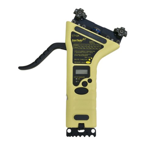
(1) The 2471F (Fig. 4) is a self-contained, battery operated, high potential megohmmeter.
Test potentials of 100, 200, and 500 volts DC are selectable by a panel switch. Current
limiting circuitry provides safe, ABSOLUTELY SHOCK-PROOF operation.
(2) A single four inch meter scale, increasing from zero at the left to infinity at the right, is
incremented from .5 to 1,000 megohms. A pushbutton on the high potential test probe
provides for conveniently activating the instrument. Flashlight type batteries are used,
and a self-contained battery test is incorporated. Solid-state circuitry provides the
means for size reduction, high sensitivity, and dependability. The meter is a rugge-
dized taut-band suspension type, which eliminates the need for pivots and jewels. The
high potential probe is shield-guarded so that stray leakage through lead insulation will
not affect the measurement accuracy.
(3) The output current of the 2471F is limited to a maximum of 30 microamperes even at
the 500 volt test potential. This current is well below human sensibility, so that there is
no sensation of current if the bare probes are touched with the tester activated. This
current limiting prevents damage to any circuitry or components that can withstand the
applied voltage, and prevents additional damage to a circuit that exhibits any insulation
deterioration.
(4) The 2471F is also protected from damage due to inadvertently connecting the probes
across an energized circuit. AC or DC voltages up to 300 volts can be safely applied.
Figure 4: General View of the Megohmmeter 2471F

2471F INSTRUCTION MANUAL
56-101-00220-B CH. 1
09 /23/08 Page 6 of 13
2. THEORY
A transistor converter increases the battery supply to the 100, 200, and 500 volt test poten-
tials selected by the panel switch. A high performance operational amplifier increases the
impedance and sensitivity of the panel meter to measure the voltage drop across the test
probes in terms of resistance. A panel control adjusts the calibration for infinity with the
probes removed from the circuit under test. The batteries are connected to the megohmme-
ter circuit through transistor switches activated by a subminiature pushbutton on the high po-
tential probe. A single receptacle provides connection to all the test lead cable circuits, and
a shieldguard isolates the high potential lead from stray leakage resistance. A panel switch
connects the meter for testing of either of the battery circuits or for megohmmeter indication.
3. SPECIFICATIONS
(1) The electrical specifications of the instrument are indicated in Tables 1 and 2.
Table 1: Current Consumption during Resistance Measurement
Test Potential (V) Max. Draw (µA)
100 ±10% 6
200 ±10% 12
500 ±10% 30
Table 2: Resistance Reading Parameters
Resistance Reading Range (MΩ) 0 to ∞
Reading Accuracy ±10 %
Megohm Increments
Low 0.5
Midscale 17
High 1000
(2) The physical specifications of the instrument are as follows.
•Weight: 3.8 lbs., approx. (with carrying case)
•Size: 8" x 6" x 4.75" approx. (with carrying case)
This manual suits for next models
1
Table of contents
Other barfield Measuring Instrument manuals

