Barista Technology PUQpress Operating instructions
Maintenance & repair manual
Puqpress -
Precision coffee tamper
VERSION 2.0.4
DATE: 14-12-2016

2
TABLE OF CONTENTS
1Introduction.......................................................................................................... 3
1.1 Warranty........................................................................................................ 3
1.2 Model types................................................................................................... 3
1.3 Revision status.............................................................................................. 3
2Operating faults.................................................................................................... 4
3Replacement of various components................................................................... 5
3.1 Replace drive unit.......................................................................................... 5
3.2 Replace induction sensor.............................................................................. 9
3.3 Clean tamper base (daily cleaning)............................................................. 12
3.4 Remove tamper base and clean cavity (weekly cleaning)........................... 13
3.5 Adjust lower clamp ...................................................................................... 15
3.6 Adjust tamping force.................................................................................... 17
4Changing tamper base....................................................................................... 18
4.1 Upper clamp types....................................................................................... 18
4.2 Determine upper clamp type ....................................................................... 18
4.3 Espresso machine brand and tamper diameter........................................... 19
5Exploded view: Total assembly.......................................................................... 19
6Order spare parts............................................................................................... 20
6.1 Order procedure.......................................................................................... 20
6.2 Recommended spare parts......................................................................... 20
6.3 Part list (all parts)......................................................................................... 21

3
1 INTRODUCTION
In this document the repair and maintenance of the Puqpress precision coffee tamper
is described. The unit is maintenance free and only has to be cleaned daily. However
due to extensive use various components wear and can break. The sequence of
replacing components is described in detail. The first step is to find the cause of the
problem. Various possible defects are listed in section 2. If the defect is not listed in
section 2, please contact us via service@puqpress.com.
All repairs should be executed by mastered people with knowledge of electrical and
mechanical components.
1.1 Warranty
As agreed by the Exclusive distribution agreement, section 6.7, the warranty period of
the product is 12 month and/or 100.000 tamping cycles (whichever first occurs).
Repairs after this period are not covered by the supplier.
The most common failure mode is the drive unit.After many cycles the drive unit wears
and can break. Replacement of drive unit can be found in section 3.1.
1.2 Model types
Many different models are available. The main difference is the tamper base diameter,
upper clamp type and power cable. All important components are similar for every
model type.
1.3 Revision status
Revision 2.0.1: Initial issue
Revision 2.0.2: Errors updated
Revision 2.0.3: Assembly sequence updated.

4
2 OPERATING FAULTS
DEFECT CAUSE REMEDY SECTION
Tamper disk does
not move, unit is ON
and display is
working
Fault in drive unit Replace drive unit 3.1
Fault in induction
sensor Replace induction
sensor. 3.2
Tamped surface is
not even Tamper base is dirty Clean tamper base 3.3
Cavity upper clamp
is dirty Remove tamper base
and clean cavity 3.4
Tamping is not level
Lower clamp not
correctly set and
portafilter can rotate
Adjust lower clamp 3.5
Tamping force is too
low Force setting too low Adjust tamping force on
display 3.6
Fault in drive unit Clean drive unit 3.1
Fault in drive unit Replace drive unit 3.1
Tamper diameter
not correct
Change to other
tamper base
diameter
Change tamper base 4.1
Change from 58mm
base to 53mm or
53mm to 58mm
Change tamper base
AND upper clamp type 4.2
Components are
missing Various
Find missing
component in exploded
view or part list and
order spare parts
5 / 6.3

5
3 REPLACEMENT OF VARIOUS COMPONENTS
3.1 Replace drive unit
Step
Description
1
Switch the device ON and activate the CLEAN mode. Tamper
base goes down. Switch OFF and remove power cable.
2
Remove main housing – top cover
3
Remove the hexagon bolt M5x100 + spring washer M5 using the
Allen key 4mm.
Remove the tamper base.
NOTE: Tamper base has left-hand screw thread!

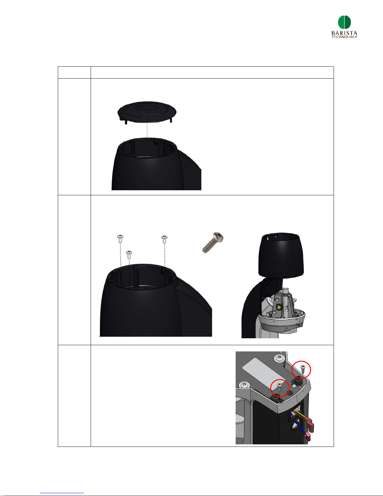
6
4
Remove the main housing – middle cover which is mounted to the
main body with 3 cross head cap screws M4x10
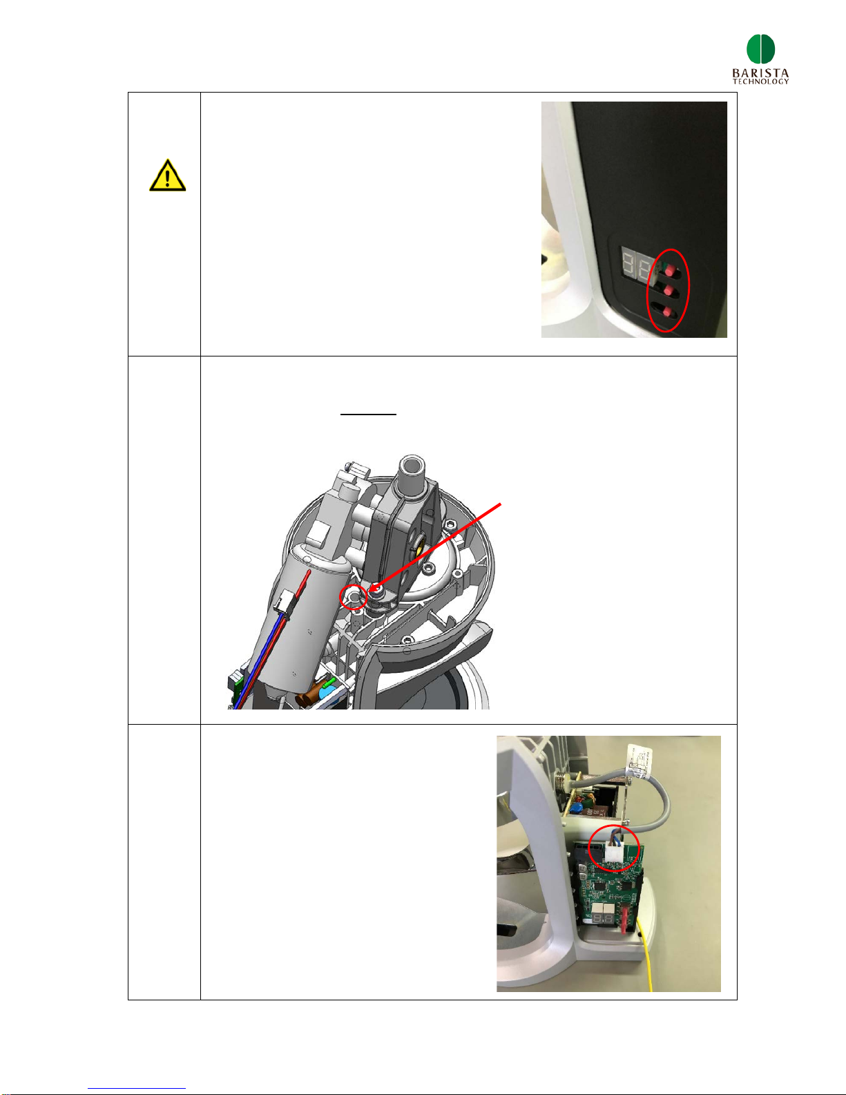
5
Unscrew 2 screws as is shown in the figure below.
6
Open the main housing – back cover.
NOTE: the push buttons (red) are fragile
so be careful when opening back cover.
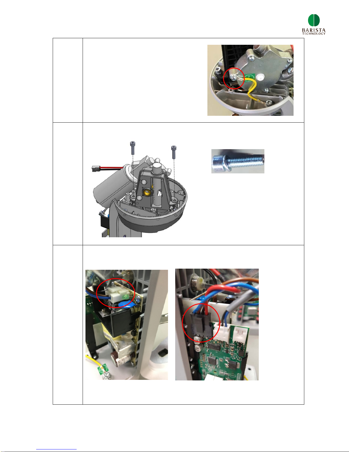
7
7
Disconnect the earthing cable from
the DC worm gear motor.
8
Unscrew 2 hexagon head cap screws M5x25.
9
Disconnect the connectors as are shown in the figures below.
8
10
Remove the drive unit and replace the drive unit with a new unit.
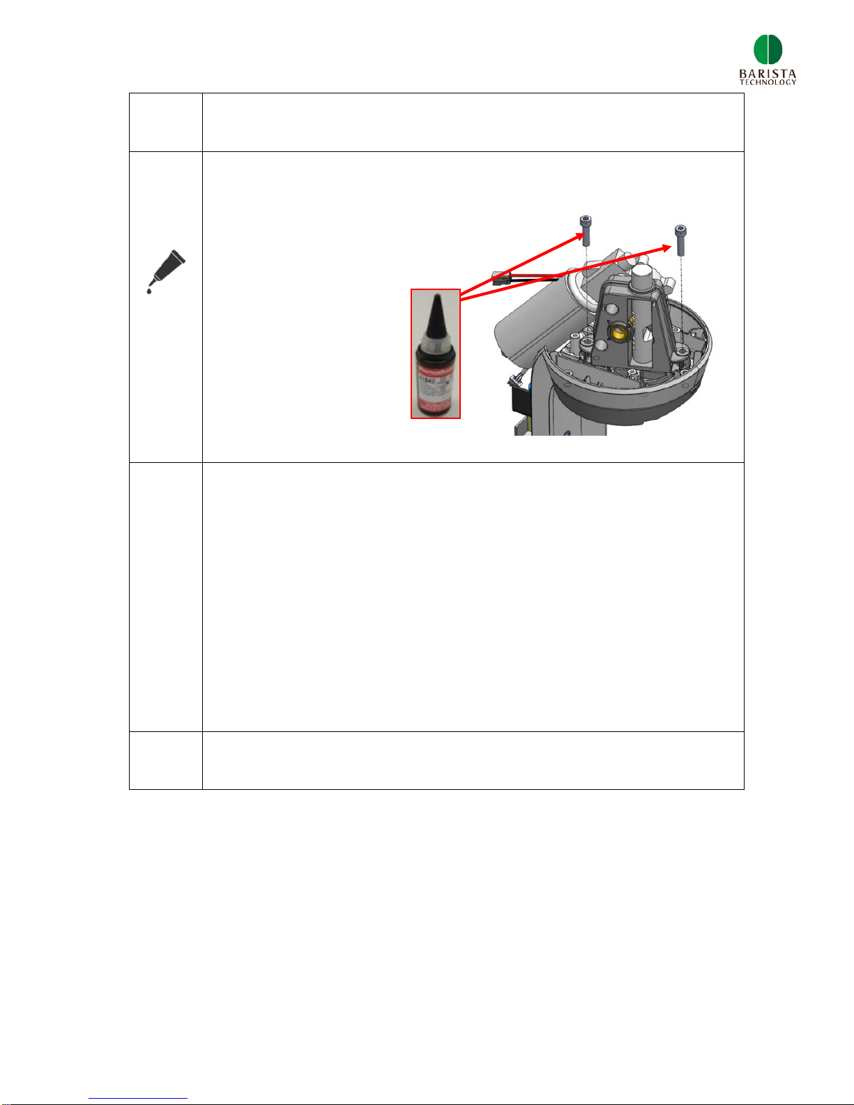
11
Mount the upper clamp to the main body with 2 hexagon head cap
screws M5x25.
Apply Permabond A1042
on screw threads.
12
Connect both connectors, see step 9.
Fasten the earthing cable to the DC motor, see step 8.
Mount the main housing – back cover, see step 5.
Mount the main housing – middle cover, see step 4.
Mount the tamper base, see step 3.
Mount the main housing – top cover, step 2.
13
Check functioning of new drive unit
9
3.2 Replace induction sensor
Step
Description
1
Remove main housing – top cover
2
Remove the main housing – middle cover which is mounted to the
main body with 3 cross head cap screws M4x10
3
Unscrew 2 screws as is shown in
the figure below.
10
4
Open the main housing – back cover.
NOTE: the push buttons (red) are fragile
so be careful when opening back cover.
5
The sensor is fixed with a set screw M5. Unscrew the set screw
using Allen key 2.5mm via the
hole as shown below. The drive
units doesn’t need to be removed.
6
Remove the induction sensor and
disconnect the connector.

11
7
Insert a new induction sensor and connect the sensor to the motor
controller PCB, see step 6.
8
Fasten the set screw M5, see step 5.
Critical: The sensor does not function when too much torque
is applied.
Check the position of the sensor after assembly
Correct
NOT correct NOT correct
9
Mount the main housing – back cover, see step 3
Mount the main housing – middle cover, see step 2.
Mount the main housing – top cover, step 1.
10
Check functioning of the new induction sensor.
12
3.3 Clean tamper base (daily cleaning)
Check our support videos: www.puqpress.com/support
Step
Description
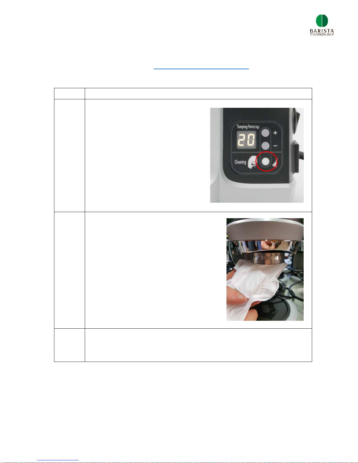
1
Turn unit ON and push the CLEAN
button. Tamper base goes down
completely.
2
Clean the tamper base with a dry towel
or a brush.
3
Push the clean button again, tamper base goes up. Cleaning
finished.
13
3.4 Remove tamper base and clean cavity (weekly cleaning)
Check our support videos: www.puqpress.com/support
Step
Description
1
Switch the device ON and activate the CLEAN mode. Tamper
base goes down. Switch OFF and remove power cable.
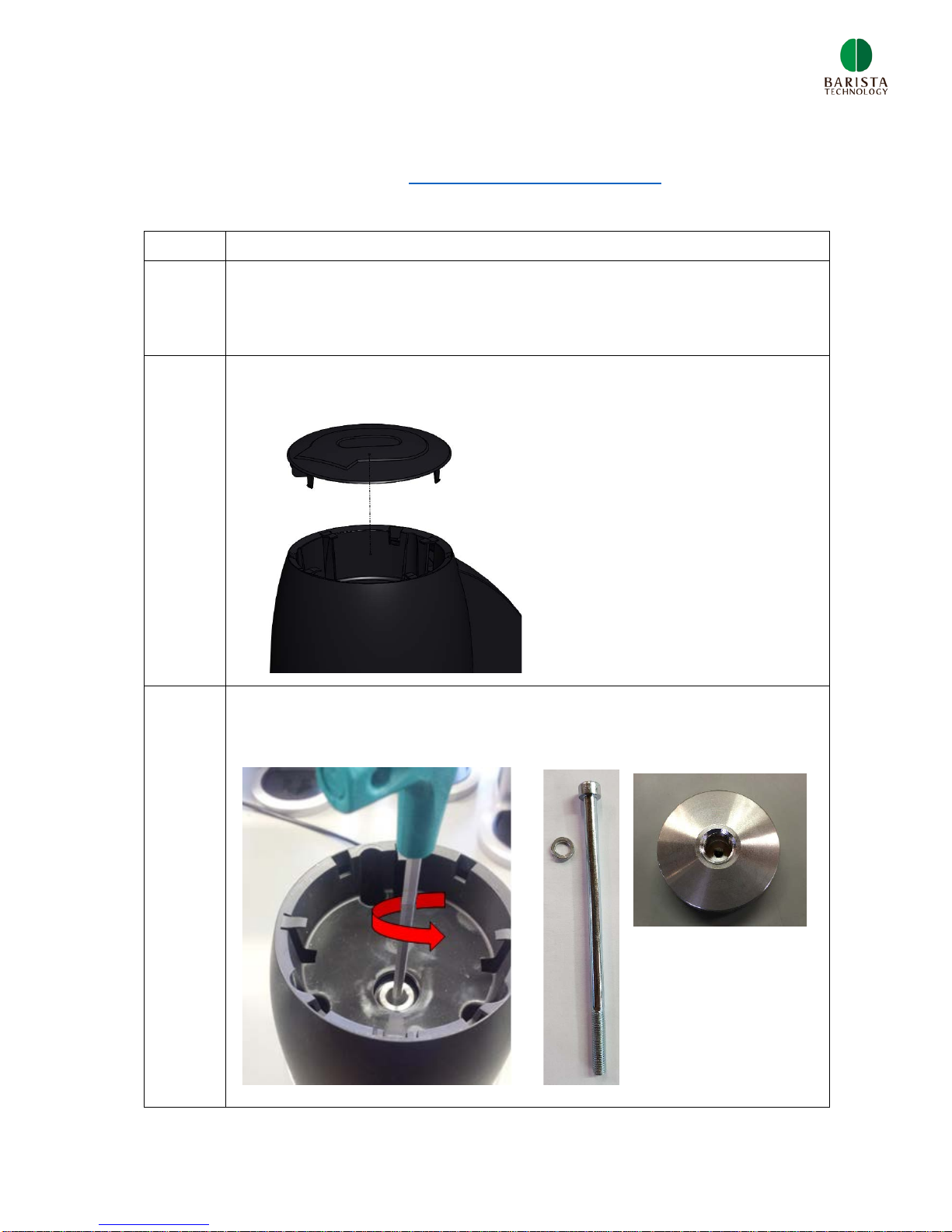
2
Remove main housing – top cover
3
Remove the hexagon bolt M5x100 + spring washer M5 using the
Allen key 4mm.

14
4
Remove the tamper base.
NOTE: Tamper base has
left-hand screw thread
5
Clean cavity with a brush.
6
After cleaning:
- Mount tamper base, step 4
- Fasten tamper base with M5x100 hex. cap screw and spring lock
washer, step 3
- Mount main housing – top cover, step 2.
15
3.5 Adjust lower clamp
Check our support videos: www.puqpress.com/support
Step
Description
1
Insert power cable and switch the Puqpress ON. Tamper heads
moves to upper position.
2
Remove power cable.
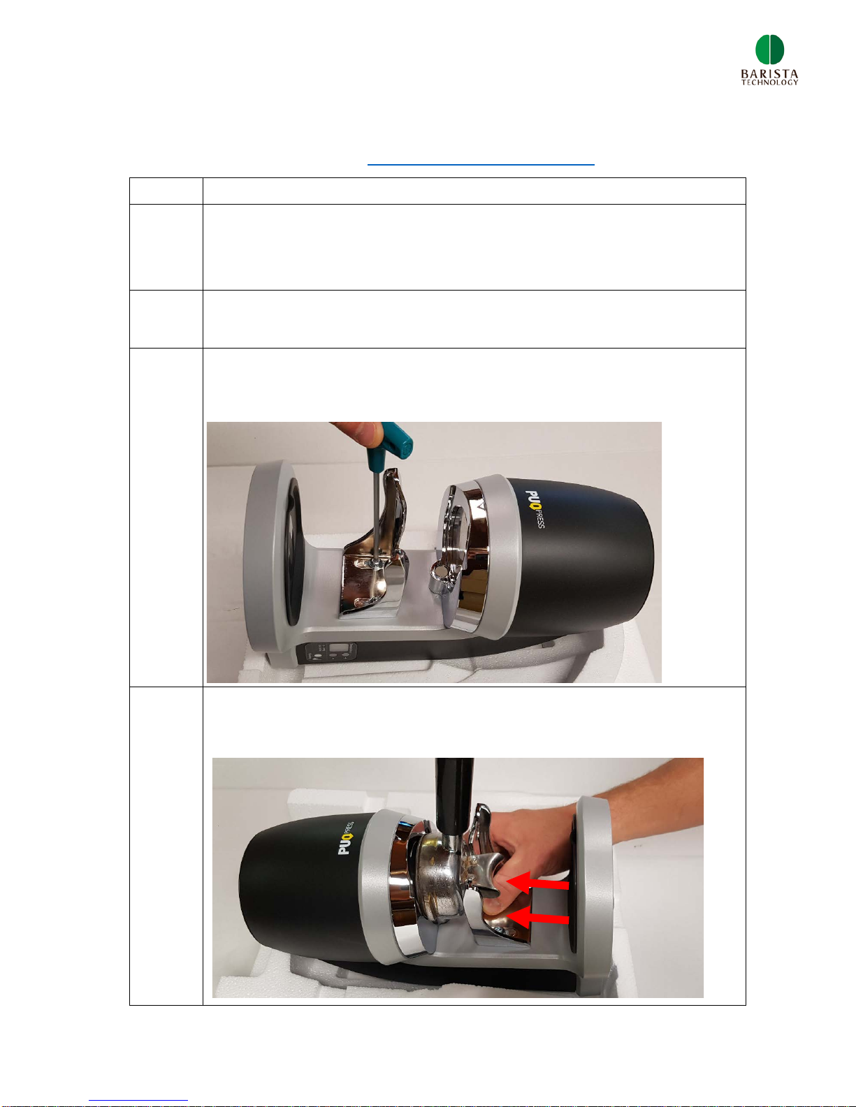
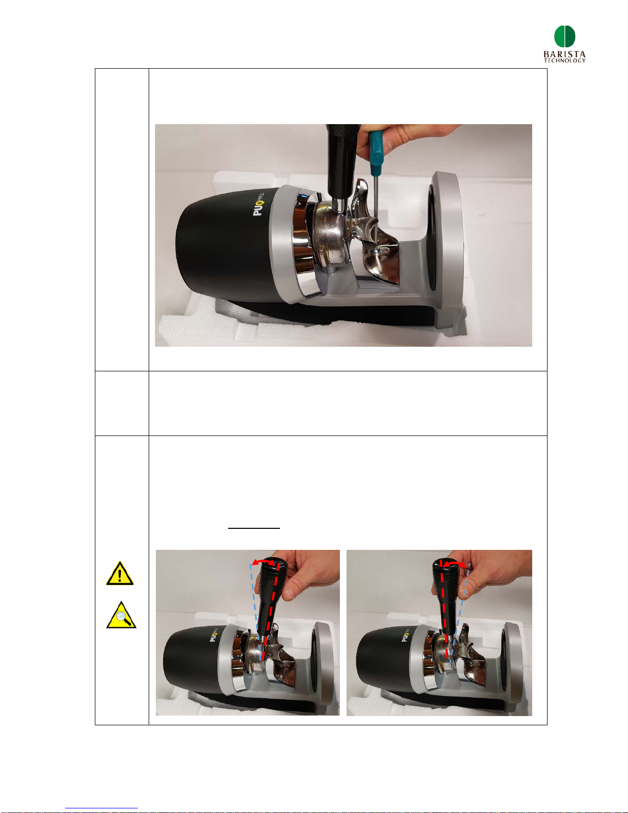
3
Put the unit with back side in the white packing box. Unscrew both
bolts as is shown below. You can find the right tool in the box.
4
Insert the portafilter and push the lower clamp upwards. Fasten
both bolts slightly
16
5
Insert the portafilter a few times and check if it’s properly clamp
between the upper and lower clamp. Fasten both bolts firmly.
6
Insert the portafilter again and check fitting. Lower clamp might be
moved during fastening of bolts.
7
Incorrect setting:
The portafilter should be clamped properly to ensure level
tamping. Movement of portafilter should be minimal. Pictures
below show incorrect setting

17
3.6 Adjust tamping force
Check our support videos: www.puqpress.com/support
Step
Description
1
Change tamping force with
+ / - push buttons.
18
4 CHANGING TAMPER BASE
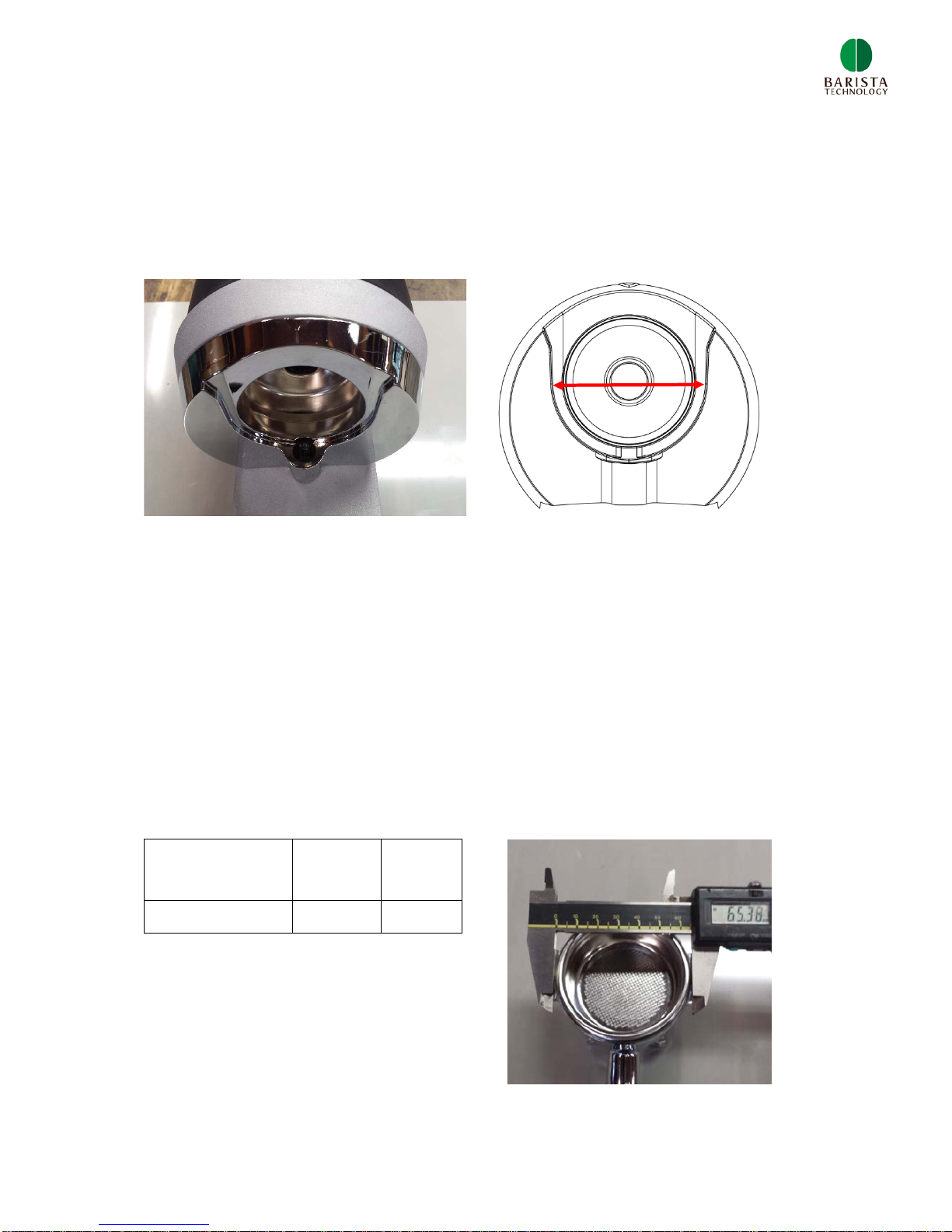
4.1 Upper clamp types
The type of upper clamp can be determined by measuring the diameter of the U-
shaped groove in the upper clamp, as is shown in figure below.
There are two types of upper clamps: 66 and 71mm. The size 71mm or 66mm is the
diameter (mm) of the U-groove, as is shown in figure 4.1 by the red arrow.
Why are we using two types of upper clamps? If the U-groove is too big compared to
the outer diameter of the filter basket, level tamping cannot be guaranteed.
4.2 Determine upper clamp type
The type of upper clamp is defined by the external diameter of the filter basket. In
order to determine the correct upper clamp type, measure the outer diameter of the
filter basket using a calliper.
Choose the correct upper clamp type using table below:
Filter basket
outer diameter
[mm]
< 66,5 >66,5
Clamp type 66 71

19
In general the outer basket diameter scales with the inner diameter (tamper size). In
table below the tamper diameters are listed with the required upper clamp type:
Tamper
diameter
[mm]
Upper
clamp type
53
66
54
66
55
66
56
71
57
71
58
71
59
71
Some filter baskets are not standard and need another upper clamp size. Therefore
check the outer and inner diameter of the filter basket in order to pick the correct
setting.
4.3 Espresso machine brand and tamper diameter
Espresso machine
brand
Tamper base
diameter
Astoria
58
Bezzera
58
Brasilia
58
Caramali
58
Cimbali
57
Conti
58
ECM
58
Elektra
58
Expobar
58
Faema
58
Gaggia
58
La Marzocco
58
La Pavoni
56
Nuova Simonelli
58
Pasquini
57
Rancilio
58
San Marco
55
Spaziale
53
Synesso
58
Unic
56
Vibiemme
58
Wega
58

20
5 SOFTWARE SETTINGS
5.1 Tamping cycle counter
1) Turn unit ON and keep in standby mode
2) Hold + button & - button for 3 seconds.
3) Display blinks and shows a number. multiply this number
by 3000, max. cycle counter is 99*3000.
4) Cycle counter disappears after 5 seconds
5.2 Clean cycles counter
1) Turn unit ON and put unit in CLEAN modus (tamper disk
goes down)
2) Hold + button & - button for 3 seconds.
3) Display blinks and shows a number. multiply this number
by 5, max. clean cycle counter is 99*5.
4) Cycle counter disappears after 5 seconds
5.3 20 cycle run-in mode
1) Turn unit OFF. Hold CLEAN button and + button, and turn
unit ON. ‘CF’ appears on display.
2) Push + button
3) Unit start to tamp 20 times as run-in mode to remove any
initial friction in the system
Table of contents


