Barnstead HP2625R User manual

Type HP2600
Hot Plate
OPERATION MANUAL
AND PARTS LIST
Series 26
Model # Voltage
HP2625R 100
HP2624R 240
HP2620R 240
HP2620R-26 120
1
LT26X4 • 2/28/05

IMPORTANT INFORMATION
This manual contains important operating and safety information. The user must carefully
read and understand the contents of this manual prior to the use of this equipment.
Safety Information ..............................................................................................................................................3
Alert Signals..................................................................................................................................................3
Warnings ......................................................................................................................................................3
Introduction..........................................................................................................................................................5
Intended Use ................................................................................................................................................5
Principles of Operation ................................................................................................................................5
General Specifications ........................................................................................................................................6
Installation ..........................................................................................................................................................7
Site Selection................................................................................................................................................7
Operation ............................................................................................................................................................8
Dial (Power) Switch) ....................................................................................................................................8
Dial (Control)Switch ......................................................................................................................................8
Maintenance and Servicing ................................................................................................................................9
Control Switch Replacement ........................................................................................................................9
Heating Element Replacement ....................................................................................................................9
Trouble Shooting ..............................................................................................................................................11
Exploded View ..................................................................................................................................................12
Replacement Parts Listing ................................................................................................................................13
Ordering Procedures ........................................................................................................................................14
Warranty ............................................................................................................................................................16
2
Table of Contents

Your Thermolyne Hot Plate has been designed with func-
tion, reliability, and safety in mind. It is the user’s respon-
sibility to install it in conformance with local electrical
codes. For safe operation, please pay attention to the
alert signals throughout the manual.
Warnings
To avoid personal injury:
1. Do not immerse unit for cleaning.
2. As with all laboratory equipment, appropriate
safety clothing, glasses, gloves and coats
should be worn when operating hot plates.
Always use appropriate hand and eye protection
when handling hazardous chemicals.
3. DO NOT remove or modify grounded power
plug. Use only properly grounded outlets to
avoid shock hazard. Not rated for use in haz-
ardous atmospheres.
4. Do not use in the presence of flammable or
combustible chemicals; top surface and ele-
ment can reach the “Flash Point Temperature” of
many chemicals. These hot plates are not explo-
sion proof. Fire or explosion may result. Unit
contains components which may ignite such
materials.
5. “Caution: Hot Surface. Avoid Contact.” The sur-
face of the hot plate will remain hot without visu-
al indication for some time after use.
To avoid electrical shock:
1. Always use a properly grounded electrical outlet
with correct voltage and current handling capaci-
ty.
2. Always disconnect the unit from the power sup-
ply prior to maintenance and servicing.
3. Refer servicing to qualified personnel.
3
Safety Information
Alert Signals
Caution
This unit is not recommended for use
in highly corrosive atmospheres.
Corrosive spills and fumes may dam-
age top and internal components.
Space unit 12 inches away from com-
bustible materials under any condi-
tions.
Warning
Warnings alert you to a
possibility of personal injury.
Caution
Cautions alert you to a possibility of
damage to the equipment.
Note
Notes alert you to pertinent facts and
conditions.
Hot Surface
Hot surfaces alert you to a
possibility of personal injury if you
come in contact with a
surface during use or for a
period of time after use.

Please note the following WARNINGS:
Warning
This warning is presented for compliance with California
Proposition 65 and other regulatory agencies and only
applies to the insulation in this product. This product con-
tains refractory ceramic, refractory ceramic fiber or fiber-
glass insulation, which can produce respirable dust or
fibers during disassembly. Dust or fibers can cause irrita-
tion and can aggravate preexisting respiratory diseases.
Refractory ceramic and refractory ceramic fibers (after
reaching 1000°C) contain crystalline silica, which can
cause lung damage (silicosis). The International Agency
for Research on Cancer (IARC) has classified refractory
ceramic fiber and fiberglass as possibly carcinogenic
(Group 2B), and crystalline silica as carcinogenic to
humans (Group 1).
The insulating materials can be located in the door, the
hearth collar, in the chamber of the product or under the
hot plate top. Tests performed by the manufacturer indi-
cate that there is no risk of exposure to dust or respirable
fibers resulting from operation of this product under nor-
mal conditions. However, there may be a risk of exposure
to respirable dust or fibers when repairing or maintaining
the insulating materials, or when otherwise disturbing
them in a manner which causes release of dust or fibers.
By using proper handling procedures and protective
equipment you can work safely with these insulating
materials and minimize any exposure. Refer to the appro-
priate Material Safety Data Sheets (MSDS) for informa-
tion regarding proper handling and recommended protec-
tive equipment. For additional MSDS copies, or additional
information concerning the handling of refractory ceramic
products, please contact the Customer Service
Department at Barnstead International at
1-800-553-0039.
4
SAFETY INFORMATION
Warning
Refer servicing to qualified personnel.
Intended Use
The Type 2600 hot plate is a heavy duty hot plate intend-
ed for procedures requiring temperatures from 425°F to
900°F (482°C). These hot plates are not to be used in the
presence of explosive vapors; this device contains com-
ponents which may ignite such materials.
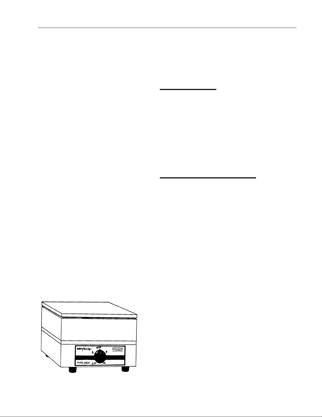
The unit consists of 1) a heated plate, 2) a four position
temperature switch and, 3) a three wire cord and plug.
See Figure 1 for the overall shape and general features of
the unit.
Principles of Operation
The top metal plate is heated by a resistance heater
embedded in a refractory material. The plate is made of
cast iron to withstand heavy loads and is suitable for use
with glass or metal vessels. The temperature of the plate
is controlled by a four position temperature switch. This
switch is used to select varying resistive loads that will
vary the watts input. The case supports the top plate, and
houses insulation, electrical connections, and temperature
control switch.
5
Introduction
Figure 1: Type HP2600 Hot Plate

Model Number HP2620R HP2620R-26 HP2624R HP2625R
Dimensions in.(cm)
Top Plate 9 x 9 (23 x 23) 9 x 9 (23 x 23) 9 x 9 (23 x 23) 9 x 9 (23 x 23)
Overall
Width 9 (23) 9 (23) 9 (23) 9 (23)
Height 6.25 (15.9) 6.25 (15.9) 6.25 (15.9) 6.25 (15.9)
Depth 10 (25.4) 10 (25.4) 10 (25.4) 10 (25.4)
Weight lb. (kg) 14.25 (6.4) 14.25 (6.4) 14.25 (6.4) 14.25 (6.4)
Electrical Ratings
Volts 240 240 100 120
Amps 4.5 4.5 9.8 9.0
Watts 1080 1080 975 1080
Phase 1 1 1 1
Frequency 50/60 50/60 50/60 50/60
Max. Temp. 900°F (482°C) 900°F (482°C) 900°F (482°C) 900°F (482°C)
6
General Specifications
Note
• All models supplied with 3-wire cord and plug.
• (-26 model) supplied with a European cord set.
• The cast iron top plate used on all models is suitable for use with glass or metal vessels.

Site Selection
Install hot plate on a sturdy surface and allow space for
ventilation.
The electrical specifications are listed on the specification
plate on the side of the hot plate. Consult Barnstead
International if your electrical service is different than
those listed on the specification plate. Prior to connecting
your Type 2600 hot plate to your electrical supply, be sure
the dial switch is in the OFF position.
7
Installation
Caution
Allow at least three inches of space
between the hot p!ate and any vertical
surface.This permits the heat from hot
plate to escape so as not to create a
possible fire hazard.
Gross weight of items placed on top of
the hot plate should not exceed 35 lb.
Warning
To avoid electrical shock, this unit
must always use a properly grounded
electrical outlet with correct voltage
and current handling capacity.

Dial (Power) Switch
The power is turned ON or OFF by means of the dial
switch. The hot plate is ON with either a clockwise or
counterclockwise movement of the dial beyond the OFF
mark.
Dial (Control) Switch
The control knob has four heating positions and an OFF
position. Position “L” holds approximately 425°F (218°C),
“LM” - 600°F (316°C), “M” 675°F (357°C), and “H” - 900°F
(482°C). If fast heating is desired, turn the knob to “H”
until the required temperature is attained, then to the
proper lower setting. If slow heating is desired, start with
the knob on “L” and increase to higher settings gradually.
To turn off hot plate, turn dial fully clockwise or counter-
clockwise to the OFF position.
8
Operation
Warning
Do not use in the presence of flamma-
ble or combustible chemicals; top sur-
face and element can reach the “Flash
Point Temperature” of many chemi-
cals. These hot plates are not explo-
sion proof. Fire or explosion may
result. Unit contains components
which may ignite such materials.
Hot Surface
“Caution: Hot Surface. Avoid Contact.”
The surface of the hot plate will
remain hot without visual indication for
some time after use.
Control Switch Replacement
1. Disconnect hot plate from power supply.
2. Turn hot plate upside down and remove bottom
cover.
3. Remove the knob and the nut securing control.
4. Disconnect six wires from control switch. Identify
or mark wires disconnected to ensure proper
placement and connection when reinstalling.
Remove defective control switch.
5. Reconnect the wires removed in step (4) to the
new control switch. Secure control switch with
the nut and the knob.
6. Replace bottom cover and secure with four
screws.
7. Turn hot plate upright and reconnect to power
supply.
Heating Element Replacement
1. Disconnect hot plate from power supply.
2. Turn hot plate upside down and remove bottom
cover.
3. Remove the knob and the nut securing control.
4. Disconnect six wires from control switch. Identify
or mark wires disconnected to ensure proper
placement and connection when reinstalling.
Remove the control switch.
5. Bend the element leads straight up and then
remove in order, the control case, insulating
spacer, top section of case, insulating plate, and
insulating block.
6. Remove defective heating element and insert
new element in the same position. Remove
9
Maintenance and Servicing
Warning
To avoid electrical shock, always dis-
connect from power supply before
maintenance and servicing. Refer
servicing to qualified personnel.
Note
Perform only maintenance described
in this manual. Contact an authorized
dealer or our factory for parts and
assistance.

glass sleeving from element leads. (See explod-
ed view for placement of insulators, nuts and
washers).
7. Bend element leads straight up and replace in
this order, the insulating block, insulating plate,
top section of case, insulating spacer, and bot-
tom section of case.
8. Replace glass sleeving on element leads. (Two
inside leads are black, the two outside leads are
red.)
9. Reconnect the wires removed in step (4) to the
control switch. Secure control switch with the
nut and the knob.
10. Replace bottom cover and secure with four
screws.
11.Turn hot plate upright and reconnect to power
supply.
10
MAINTENANCE AND SERVICING

The Troubleshooting Tips section is intended to aid in defining and correcting possible service problems.
When using the chart, select the problem category that resembles the malfunction, then proceed to the possi-
ble causes category and take necessary corrective action.
Problem Possible Causes Solutions
Hot Plate does not heat. 1. No power. 1. Check power source and fuse.
2. Defective electrical hookup. 2. Repair electrical hookup.
3. Burned out heating element. 3. Replace defective heating element.
4. Defective control switch. 4. Replace control switch.
Hot Plate does not hold 1. Defective control switch 1. Replace control switch.
temperature
11
Troubleshooting
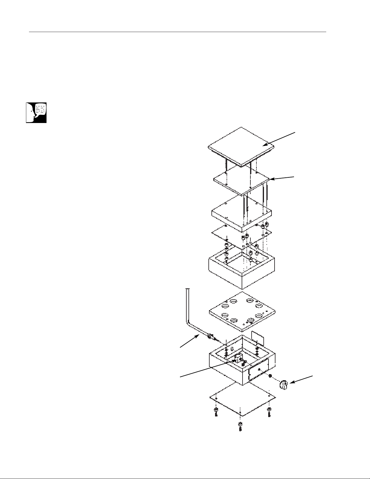
12
Exploded View
Note
When ordering replacement parts be
sure to order by part numbers - not by
key numbers.
Exploded View HP2600/Series
1
2
3
45
Model Type: HP2600
Product Name: Thermolyne Hot Plate
Series Number: 26
Key Part # Description
1PT26X1B Plate Assembly
2EL26X1 Element for HP2625R, 120V
EL26X2 Element for HP2620R & HP2620R-26, 240V
EL26X5 Element for HP2624R, 100V
3CR25X1 Cord Set for HP2625R 120V
CR26X1 Cord Set for HP2620R 240v
CR25X1 Cord Set for HP2624R, 100V
CR26X2 Cord Set for HP2620R-26, 240V
4SWX9 Switch
5KBX1 Knob
13
Replacement Parts
Warning
To avoid electrical shock, always dis-
connect from power supply before
maintenance and servicing. Refer
servicing to qualified personnel.
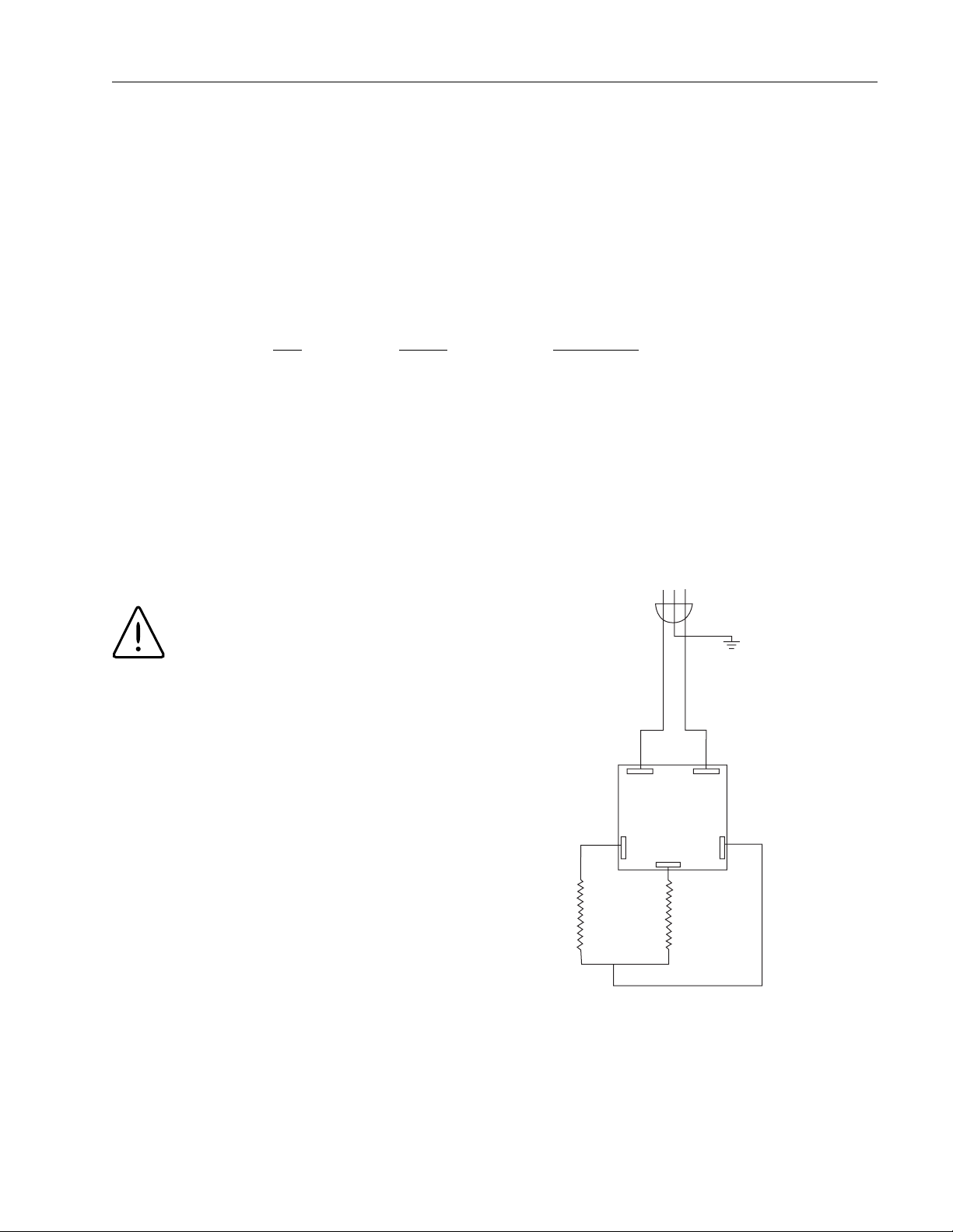
SWITCH
31
2
NL
1
ELEMENT
WHT BLK
LINE

Please refer to the Specification Plate for the complete
model number, serial number, and series number when
requesting service, replacement parts or in any corre-
spondence concerning this unit.
All parts listed herein may be ordered from the Barnstead
International dealer from whom you purchased this unit or
can be obtained promptly from the factory. When service
or replacement parts are needed we ask that you check
first with your dealer. If the dealer cannot handle your
request, then contact our Customer Service Department
at 563-556-2241 or 800-553-0039.
Prior to returning any materials to Barnstead International,
please contact our Customer Service Department for a
“Return Materials Authorization” number (RMA). Material
returned without a RMA number will be refused. Minimum
invoice: $25.
14
Ordering Procedures

15

Barnstead International (“BARNSTEAD”) warrants that a product manufactured by Barnstead shall be free of
defects in materials and workmanship for two (2) years from the first to occur of (i) the date the product is sold by
BARNSTEAD or (ii) the date the product is purchased by the original retail customer (the “Commencement
Date”). Except as expressly stated above, BARNSTEAD MAKES NO OTHER WARRANTY, EXPRESSED OR
IMPLIED, WITH RESPECT TO THE PRODUCTS AND EXPRESSLY DISCLAIMS ANY AND ALL WARRANTIES,
INCLUDING BUT NOT LIMITED TO, WARRANTIES OF DESIGN, MERCHANT ABILITY AND FITNESS FOR A
PARTICULAR PURPOSE.
An authorized representative of BARNSTEAD must perform all warranty inspections. In the event of a defect
covered by BARNSTEAD’s warranty, BARNSTEAD shall, as its sole obligation and exclusive remedy, provide free
replacement parts to remedy the defective product. In addition, for products sold by BARNSTEAD within the con-
tinental United States or Canada, BARNSTEAD shall provide provide free labor to repair the products with the
replacement parts, but only for a period of ninety (90) days from the Commencement Date.
BARNSTEAD’s warranty provided hereunder shall be null and void and without further force or effect if there is
any (i) repair made to the product by a party other than BARNSTEAD or its duly authorized service representa-
tive, (ii) misuse (including use inconsistent with written operating instructions for the product), mishandling, con-
tamination, overheating, modification or alteration of the product by any customer or third party or (iii) use of
replacement parts that are obtained from a party who is not an authorized dealer of BARNSTEAD.
Heating elements, because of their susceptibility to overheating and contamination, must be returned to the
BARNSTEAD factory and if, upon inspection, it is concluded that failure is due to factors other than excessive
high temperature or contamination, BARNSTEAD will provide warranty replacement. As a condition to the return
of any product, or any constituent part thereof, to BARNSTEAD’s factory, it shall be sent prepaid and a prior writ-
ten authorization from BARNSTEAD assigning a Return Materials Number to the product or part shall be
obtained.
IN NO EVENT SHALL BARNSTEAD BE LIABLE TO ANY PARTY FOR ANY DIRECT, INDIRECT, SPECIAL, INCI-
DENTAL, OR CONSEQUENTIAL DAMAGES, OR FOR ANY DAMAGES RESULTING FROM LOSS OF USE OR
PROFITS, ANTICIPATED OR OTHERWISE, ARISING OUT OF OR IN CONNECTION WITH THE SALE, USE
OR PERFORMANCE OF ANY PRODUCTS, WHETHER SUCH CLAIM IS BASED ON CONTRACT, TORT
(INCLUDING NEGLIGENCE), ANY THEORY OF STRICT LIABILITY OR REGULATORY ACTION.
The name of the authorized Barnstead International dealer nearest you may be obtained by calling 1-800-446-
2555 Kerper Boulevard
P.O. Box 797
Dubuque, Iowa 52001-0797
Phone: 563-556-2241 or 800-553-0039
Fax: 563-589-0516
E-mail: [email protected]
www.barnstead.com
Two Year “Bumper to Bumper”
Warranty
This manual suits for next models
3
Table of contents
Other Barnstead Cooktop manuals

Popular Cooktop manuals by other brands


Fisher & Paykel
Fisher & Paykel MINIMAL CID834DTB4 installation guide

Frigidaire
Frigidaire 318203628 use & care

Avantco
Avantco ICBTM20 user manual

Concept2
Concept2 PDV 4660 manual

Blue Star
Blue Star RBCT304BSS Installation and user instructions

Silvercrest
Silvercrest SIKP 2000 C1 User manual and service information


