Barreto E1420S Owner's manual

1320/1420/1620 Owner’s-Operator’s Manual
2/16/16
Page 1 of 20
THE
MODELS E1320H/1420S/1620B
HYDRAULIC REAR TINE
TILLER
OWNER’S/OPERATOR’S MANUAL
CONGRATULATIONS!
You are now the proud owner of the BARRETO Model 1320 or 1620 tiller. Please take a
moment of your time to look over the following information. Familiarize yourself with the
tiller, its characteristics, and method of operation. Pay particular attention to the safety and
operating instructions.
If you have any questions or need replacement parts in the future, please contact us at
your convenience. Our toll-free phone number, fax and email are listed below and parts
may be ordered through any of these methods.
THANK YOU for your patronage and confidence in BARRETO equipment.
Barreto Manufacturing, Inc. Innovative Equipment Engineered to Last
66498 Hwy 203, La Grande, OR 97850
(800) 525-7348 (541) 963-7348
FAX (541) 963-6755
E-Mail: info@barretomfg.com
Web Site: http://www.barretomfg.com
Machine Identification Record
Barreto Customer number ________________________
Machine model number ________________________
Machine serial number ________________________
Engine manufacturer ________________________
Engine model number ________________________
Engine serial number ________________________
*Always follow manufacturer instructions*
*AAA Rent-All 225-291-1356*

1320/1420/1620 Owner’s-Operator’s Manual
2/16/16
Page 2 of 20
TABLE OF CONTENTS
TILLER ASSEMBLY INSTRUCTIONS 2
BREAK IN PROCEDURE 3
SERVICE INFORMATION 3
BARRETO WARRANTY 4
HOUR METER 4
HONDA GX270 SCHEMATIC 5
SUBARU EX40 SCHEMATIC 6
BRIGGS 16 HP SCHEMATIC 6
HYDRAULIC SCHEMATIC 7
SPECIFICATIONS 8
TROUBLESHOOTING 9
TINE MOTOR REMOVAL AND REINSTALLATION 12
OPERATING INSTRUCTIONS 13
SAFETY INSTRUCTIONS 14
SAFETY INSTRUCTIONS OVERVIEW 15
LOCATION OF UNDERGROUND UTILITIES 17
WORKSITE ASSESSMENT 18
CONTACT WITH UNDERGROUND UTILITIES 19
INDEX 20
ASSEMBLY
INSTRUCTIONS
1. Remove the tiller from the shipping crate. Please inspect immediately for any damage and
notify the shipping company and Barreto Manufacturing, Inc. right away if any is found.
2. Screw the handle bar adjustment crank into the lower handle bar adjuster pin.
3. Fasten the handle bar to the tiller using the 1/2" x 3" bolt supplied.
4. Adjust the clutch cable by removing all slack in the lever.
5. Check the reservoir according to instructions in the service information on the following page.
6. Fill the engine with fuel and oil according to the engine manual.
7. Free wheel hubs: Pull one freewheeling pin slightly, using the split ring. Rotate the pin until
the 1/8" diameter roll pin aligns with the slot in the mounting plate. Allow the pin to slide
through the slot. Repeat for the other wheel. Roll the tiller until each pin drops into a hole in
the hub. The hubs are now locked.
8. Uncoil the wire for the remote engine on/off switch. Route the wire along the clutch cable
to the engine and secure with the cable ties provided. Splice this wire to the kill switch wire
on the engine with the electrical splice provided.
9. When documentation refers to “right side” or “left side”, it is relative to the operator’s
position with both hands on the handlebars.
*Always follow manufacturer instructions*
*AAA Rent-All 225-291-1356*

1320/1420/1620 Owner’s-Operator’s Manual
2/16/16
Page 3 of 20
BREAK IN
PROCEDURE
KEEP ALL PERSONNEL CLEAR OF
M
A
CH
I
N
E
DURING BREAK IN TO PREVENT
I
N
J
U
R
Y!!
Before using the tiller, lower the depth bar to raise the tines off the ground. Tape the clutch
handle in the closed position and let the machine run for 30 minutes at half throttle with tines
in motion.
SERVICE
INFORMATION
1. Check reservoir level using sight glass on the left side of the tank. If required, add to reservoir tractor
transmission / hydraulic fluid. For machine use in ambient temperatures between +32°F (0°C) and
+90°F (32°C) hydraulic fluid ISO 68 is recommended. If the machine is operated at temperatures
below +32°F (0°C) then hydraulic fluid ISO 46 is recommended. Recheck oil level after the tiller
has been run and oil has been circulated through the wheel and tine motors. Routinely check
the level thereafter. DO NOT OVERFILL THE TANK.
2. Change the hydraulic oil filter after the first 50 hours of use. Change it after every 200 hours
thereafter.
3. Add 1 quart of hydraulic oil to the reservoir with each hydraulic oil filter change.
4. Check the tine bolts after each use and tighten as needed. Check all hydraulic fittings for
leaks and tighten if necessary.
5. Tines should be changed as often as needed for the machine to do a satisfactory and efficient
tilling job. Use Loctite 271 (red) on tine bolt threads to prevent loosening.
6. The grease zerk on the outboard end of the tine shaft flange bearing should be greased after
every 4 to 8 hours of use.
7. Grease zerks on the axle ends (to lube wheel hubs) should be greased once a week or so,
depending upon freewheel use.
IMPORTANT: The engine is normally serviced prior to shipping. However, shipping
regulations may prohibit this. Check levels and add oil and fuel as required before starting.
Service according to the engine manual before starting.
IMPORTANT: If the couplers between the engine and the pump are
moved or removed for any reason, it is CRITICAL that they have a 1/8”
gap between them when reinstalled. Failure to have this gap will result in
rapid wear and failure of your pump!
NOTE: It is very important to move the fuel shutoff lever to the closed position after
stopping the engine. Failure to do so could cause fuel to leak down into the cylinder
and crankcase. Damage resulting from this will void your engine warranty and not be
covered.
WARNING: Running the tiller without hydraulic oil will cause serious damage to the hydraulic
pump. CHECK THE RESERVOIR LEVEL BEFORE STARTING THE MACHINE.
*Always follow manufacturer instructions*
*AAA Rent-All 225-291-1356*

1320/1420/1620 Owner’s-Operator’s Manual
2/16/16
Page 4 of 20
BARRETO MANUFACTURING,
INC.
EQUIPMENT
WARRANTY
Barreto Manufacturing, Inc. warrants all BARRETO equipment to be free of defects in material
and workmanship for a period of one (1) year, dating from delivery to the original user.
This Warranty is in lieu of all other warranties, whether written or implied, and is limited to:
1. Replacement of parts returned to the dealer and/or factory and determined defective upon
inspection. (Replacement for parts to dealers shall be at dealer cost plus shipping charges.)
2. Time for pick-up and/or delivery, transportation or service calls by dealers is excluded.
Manufacturer reserves the right to determine reasonable time required for repair.
Warranty does not apply to damage caused by abuse or neglect. Time and materials required for
normal maintenance and service are also excluded from warranty coverage.
Engines, engine accessories, batteries and tires are warranted by the original manufacturers
and are not covered by the Barreto Equipment Warranty. Wear parts such as tiller tines,
sprockets, bearings, trencher chain parts including teeth, stump grinder cutting teeth & holders,
etc. are also excluded unless it can be determined that a defect has contributed to premature wear.
HOUR METER
The DGI®TACH/HOUR hour meter tracks the hours of machine operation in order for routine
maintenance to be performed on a timely basis.
Your DGI® hour meter is pre-set at the DGI® factory to go into Flash Alert mode at 25-hour
intervals. Although the engine manufacturer does not require changing engine oil this often, due
to heavy-duty use and extreme conditions inherent to tiller use, Barreto Manufacturing
strongly recommends frequent oil changes.
Refer to this manual for equipment service requirements and to the Engine Manual for engine
service requirements.
While Flash Alert is active, hold the tip of the RESET TOOL (Key Kancel Wand) against the
meter as shown. Within several seconds, the display will stop flashing indicating the Service
Interval has been reset. If the wand gets lost, a small mechanic’s pick-up magnet will work.
RESET TOOL
*Always follow manufacturer instructions*
*AAA Rent-All 225-291-1356*

1320/1420/1620 Owner’s-Operator’s Manual
2/16/16
Page 5 of 20
ELECTRICAL SCHEMATIC -HONDA GX390
TECHNICAL
&
CONSUMERINFORMATION
Wiring Diagrams
Oil Alert® and Electric
Starter Types
ENGINE SWITCH
IG
E
ST
BAT
OFF
o-
-o
ON
START
o-
-o
Gr
LEVEL
SWITCH
81/W
Engine Types with Oil Alert® and
Without
Electric
Starter
*Always follow manufacturer instructions*
*AAA Rent-All 225-291-1356*

1320/1420/1620 Owner’s-Operator’s Manual
2/16/16
Page 6 of 20
ELECTRICAL SCHEMATIC – SUBARU EX40
ELECTRICAL SCHEMATIC – BRIGGS VANGUARD 16 HP V-TWIN
*Always follow manufacturer instructions*
*AAA Rent-All 225-291-1356*

1320/1420/1620 Owner’s-Operator’s Manual
2/16/16
Page 7 of 20
HYDRAULIC SCHEMATIC
*Always follow manufacturer instructions*
*AAA Rent-All 225-291-1356*

1320/1420/1620 Owner’s-Operator’s Manual
2/16/16
Page 8 of 20
SPECIFICATIONS
MODEL NUMBER 1320/1420/1620
DIMENSIONS
Weight 560 lbs. (254.01 kg)
Height 44” (1.12 m)
Length 77” (1.96 m)
Width 27” (685.8 mm)
ENGINE
Engines Honda GX390
Subaru EX40
Briggs Vanguard 16 hp V-Twin
Fuel Gasoline
Power: hp (kW) at 3600 RPM H-11.7 hp (8.73 kW)
Power: hp (kW) at 3600 RPM S-14 hp (10.3 kW)
Power: hp (kW) at 3600 RPM B-16 hp (11.93 kW)
Fuel Capacity H-1.72 U.S. gallons (6.5 liters)
S-1.85 U.S. gallons (7 liters)
B-1.75 U.S. gallons (6.6 liters)
Engine Oil Capacity H-1.16 quarts (1.1 liters)
S-1.27 quarts (1.2 liters)
B-1.38 quarts (1.36 liters)
Hour Meter Standard
Electric Start May or may not have
HYDRAULIC SYSTEM
Reservoir Capacity 14 U.S. gallons (52.99 liters)
OPERATIONS
Ground Drive, Forward 0-80 rpm
Tine Speed 260 rpm
*Always follow manufacturer instructions*
*AAA Rent-All 225-291-1356*

1320/1420/1620 Owner’s-Operator’s Manual
2/16/16
Page 9 of 20
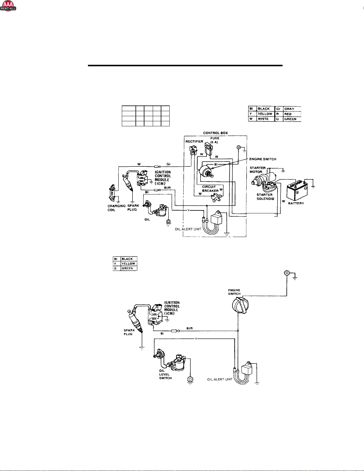
1320H/1420S/1620B TILLER TROUBLESHOOTING GUIDE
CAUTION: ALWAYS USE EXTREME CARE WHEN TROUBLE SHOOTING OR MAKING
ADJUSTMENTS ON THE TILLER. STAY CLEAR OF TINES WHEN ENGINE IS
RUNNING. ALWAYS SHUT THE ENGINE OFF BEFORE DISASSEMBLING ANY
COMPONENT.
A. ENTIRE HYDRAULIC SYSTEM DOES NOT OPERATE AND THE ENGINE IS
NOT UNDER LOAD
1. Broken or improperly adjusted clutch
(actuator) cable.
2. Low hydraulic oil in tank.
3. Hydraulic pump-to-engine coupler has
slipped.
4. Hydraulic pump worn or tine motor relief
valve not functioning properly.
If broken, replace. Remove slack then
adjust for 7/16” to 1/2" movement at
actuator lever pin.
Fill to center of the sight glass.
Check for wear and replace both coupler
halves and rubber spider as needed.
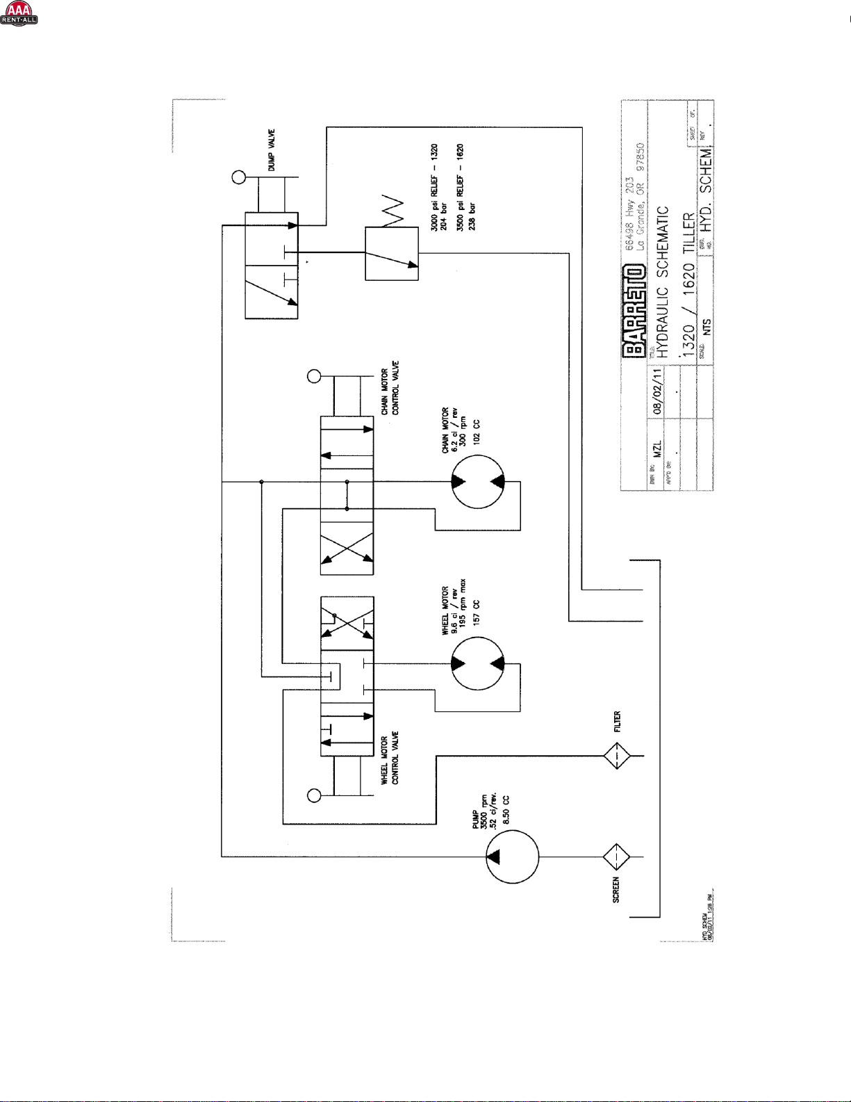
Follow the series of tests described below
Remove the tank end (at the T-fitting) of the hose that goes from the pump to the tank. Start the
engine and with the tines and wheels in neutral, pump off about four gallons of hydraulic oil into
a clean bucket. (The .52 CID pump, @ 1000 PSI & 3000 RPM, should pump at the rate of 6.5
GPM.) Replace the hose and remove the tank lid. Block the tines with a short 4 X 4 and stand to
the side.
With tines selected to ON (forward) rotation, squeeze the clutch lever and check to see where the
oil enters the tank. If the pump is good, the oil will enter through the relief valve or the return line
from the filter. If the oil returns only through the filter return, the tine-drive motor is bad.
If the oil returns through the relief valve but does not kill the engine, check the out-put pressure
of the pump. To do this, "T" a 4000 pound gauge into the line at the tank. DO NOT B
L
O
C
K
THE LINE OR DEAD-HEAD THE GAUGE INTO THE LINE. With the tines in forward and
blocked, activate the system as before. The relief valve for the 1320H is set at 3000 pounds, and
3500 pounds for the 1620B. If the gauge reaches the specified pressure, the relief valve is OK.
If not, the relief valve is bad and needs to be replaced.
If the pressure reaches 3000 pounds but there is only a small amount of oil returning, the pump is
worn and should be replaced.
*Always follow manufacturer instructions*
*AAA Rent-All 225-291-1356*

1320/1420/1620 Owner’s-Operator’s Manual
2/16/16
Page 10 of 20
TROUBLESHOOTING GUIDE (CONTINUED)
B. TINES FAIL TO ROTATE BUT WHEELS DRIVE.
1. Clutch cable stretched so needs
adjustment.
2. Tine motor worn.
Remove cable slack then adjust for 7/16” to
1/2" movement at actuator lever pin.
Rebuild or replace motor. New motors are
available from Barreto Manufacturing, Inc.
C. WHEELS FAIL TO TURN BUT TINES ROTATE
1. Wheel axle keys have been sheared or
removed.
2. Free-wheeling hubs unlocked.
Replace keys.
Lock hubs in place.
D. ENGINE LUGS DOWN OR DIES AND WHEELS AND TINES DO NOT TURN.
1. Rocks or other obstruction blocking tines.
2. Tine shaft bound with wire, vines, or
grass.
3. Tilling depth too great for soil conditions.
4. Outboard tine shaft bearings binding.
5. Engine improperly tuned or maintained.
6. Low oil alert causes engine to shut down.
7. Engine losing power due to wear.
Shut OFF engine and remove obstruction.
Shut OFF engine and remove debris,
especially at the ends.
Shut OFF engine and lower depth bar to
raise the tines, decreasing tilling depth.
Lubricate or replace bearings as needed.
See engine manual and correct as needed.
This may occur if tilling on hills, (not
advised). Level the tiller and check engine
oil level. Fill if required. Oil alert should
reset. See engine manual.
See engine manual.
*Always follow manufacturer instructions*
*AAA Rent-All 225-291-1356*

1320/1420/1620 Owner’s-Operator’s Manual
2/16/16
Page 11 of 20
TROUBLESHOOTING GUIDE (CONTINUED)
E. OIL LEAKS IN HYDRAULIC SYSTEM.
1. Fittings are loose.
2. Worn or broken hoses.
3. Oil around tine motor shaft.
Tighten as required.
Replace as necessary.
Inspect tine motor for leaking shaft seal.
Rebuild or replace motor. New motors are
available from Barreto Manufacturing, Inc.
F. EXCESSIVE FOAMING OF HYDRAULIC OIL FROM VENT HOSE.
1. Improper oil used.
2. Pump sucking air.
3. Hydraulic pump is faulty.
Verify that hydraulic oil used has anti-
foaming additives. *
Inspect and tighten fittings on intake side of
pump.
Test using procedure in section A4 above.
* Recommended oil is Chevron 1000 or equivalent hydraulic oil with anti-foaming and anti-
wear additives. Hydraulic oil should have an ISO/AW rating of 68.
*Always follow manufacturer instructions*
*AAA Rent-All 225-291-1356*

1320/1420/1620 Owner’s-Operator’s Manual
2/16/16
Page 12 of 20
REMOVAL OF TINE DRIVE
HYDRAULIC
MOTOR,
HUB, AND MOTOR
MOUNT
1. Remove tine cover #1008 (twelve 5/16 x 1 bolts).
2. Remove the 4 bolts (3/8 x 1) from outboard bearing assy, p/n 10144.
3. Remove the 5 bolts (3/8 x 1) from the right side plate.
4. Remove the 4 tines closest to the hydraulic motor.
5. Remove the tine shaft, p/n 01011.
6. Remove the hoses from the tine motor.
7. Remove the tine motor guard bolts, 4 of (3/8 x1-1/4) and 4 of (3/8 x 1) from the motor
mount bracket and slip the motor out.
8. Remove the tine hub from the motor. Remove the hub nut from the motor shaft, and
then insert 2 bolts (3/8 x 1 NC) into the threaded holes on the tine hub. Apply slight
pressure against the motor and then tap the tine hub with a brass or plastic hammer.
Tapered hub will slide off.
9. Remove the motor from the mounting bracket.
REINSTALLATIONOF TINE DRIVE HYDRAULIC
MOTOR
1. Install mounting bracket.
2. Install the tine hub, use Loctite on the motor shaft threads and tighten nut.
3. Reassemble in reverse order that parts were removed.
*Always follow manufacturer instructions*
*AAA Rent-All 225-291-1356*

1320/1420/1620 Owner’s-Operator’s Manual
2/16/16
Page 13 of 20
OPERATING INSTRUCTIONS
1. READ SAFETY
INSTRUCTIONS
BEFORE
O
PER
A
T
I
N
G
!
2. Be sure engine oil and hydraulic oil are at proper levels before starting the tiller.
3. STUDY AND UNDERSTAND
CONTROLS
BEFORE BEGINNING
O
PER
A
T
I
O
N!
4. NEVER RUN THE MACHINE IN REVERSE WHILE TINES ARE
R
O
T
A
T
I
N
G
!
5. Always move the tine control lever to "OFF" before reversing wheels.
6. The TINE DRIVE lever should be set at "OFF" when moving the tiller from place to
place while not tilling.
7. CLUTCH (ACTUATOR) LEVER: (At left handle grip) Activates the wheel drive and
tine rotation controls when squeezed. When released, all motion stops.
8. WHEEL DRIVE LEVER: The wheel speed is variable both in forward and reverse.
Moving the WHEEL DRIVE lever to the right causes the tiller to go forward; moving
to the left to back up. The farther the control lever is moved away from center, the
faster the tiller will travel. When the lever is centered, the wheels are locked in a
neutral or park position.
9. TINE DRIVE LEVER: The tines operate at a constant speed. The TINE DRIVE
lever must be moved all the way over to either the forward "ON" position or “REV”
position when tilling. If an object becomes lodged in the tines, put the WHEEL
DRIVE lever in neutral and change direction of the tines to dislodge it.
10. OPERATE TILLER ON LEVEL GROUND ONLY!
11. TILLING OPERATION: In most soil and sod conditions, the depth bar can be set
with the pin in the third hole from the top.
When starting to till, move the TINE DRIVE lever to the ON (forward) or REV
position. Tines will dig in either the forward or reverse rotating direction. Squeeze
the CLUTCH LEVER completely to engage the tines.
Move the WHEEL DRIVE lever to the right until the desired wheel speed is
reached.
Under most conditions, at least two passes must be made. For deeper tillage, move
the depth bar up one hole at a time.
*Always follow manufacturer instructions*
*AAA Rent-All 225-291-1356*

1320/1420/1620 Owner’s-Operator’s Manual
2/16/16
Page 14 of 20
SAFETY
INSTRUCTIONS
1. READ SAFETY AND OPERATING INSTRUCTIONS BEFORE OPERATING!
2. DO NOT LEAVE TILLER UNATTENDED WITH ENGINE RUNNING.
3. Always park on level surface, never on an incline.
4. USE EXTREME CAUTION IF TRANSPORTING TILLER DOWN ANY INCLINE,
ESPECIALLY
IF USING RAMPS OFF A PICK-UP
TR
U
C
K
.
5. The SAFETY CLUTCH (ACTUATOR) lever on the left handlebar is for operator
protection. DO NOT TAPE DOWN OR OTHERWISE BY-PASS THIS
SAFETY FEATURE!
6. Objects may become airborne while operating tiller. Wear safety goggles, hard hat,
protective footwear and hearing protection while operating or observing!
7. Rotating tines can cause serious injury. KEEP HANDS AND FEET CLEAR!
8. KEEP TINE COVER CLOSED and MACHINE LEVEL while tines are operating.
9. Buried cables or gas lines can cause serious injury or death. Contact local agencies for
location.
10. Fuel exhaust and fuel fumes can cause illness or death. Operate outdoors and avoid
breathing exhaust and fumes.
11. Fuel-fumes can catch fire or explode. Do not smoke or operate near flames or sparks.
12. Hydraulic oil is under extreme pressure and can get under skin and burn or poison.
Check for leaks with cardboard.
13. Muffler and engine get hot enough to cause serious burns. Do not touch until cool.
*Always follow manufacturer instructions*
*AAA Rent-All 225-291-1356*

1320/1420/1620 Owner’s-Operator’s Manual
2/16/16
Page 15 of 20
SAFETY INSTRUCTIONS OVERVIEW
READ SAFETY AND OPERATING INSTRUCTIONS BEFORE OPERATING!
USE COMMON SENSE AND PLENTY OF IT!
The CLUTCH LEVER on the left handlebar is for the operator’s protection. All motion stops when the
lever is released. DO NOT TAPE THE CLUTCH LEVER UP or otherwise by-pass this safety
feature!
Call before you dig.If you do not call, you may cause an accident; suffer injuries or death; cause
interruption of services; damage the environment; and/or incur project delays. Expect to be held liable
for any damages caused, if you fail to call.
DANGER: Buried electric cables or gas lines can cause serious injury or death if struck with
tines. Always determine location of utilities before tilling.
WARNING: Fiber optic cables convey laser light that can injure your eyesight.
STAY CLEAR of moving parts on the tiller.
Wear safety goggles and a hard hat while operating or observing!
WARNING: The tines may throw stones and debris.
Wear adequate hearing protection while operating or observing.
WARNING: Exposure to loud noise is cumulative and may permanently
damage your hearing.
Wear safety boots and gloves. Wear close-fitting clothing. Contain long hair.
Do not wear jewelry. Wear reflective clothing if working near traffic.
Only operate outdoors and avoid breathing engine exhaust and fumes.
WARNING: Engine exhaust contains carbon monoxide gas that is toxic.
Breathing it can cause unconsciousness and death.
Adequate lighting is required, daylight or artificial, for safe operation of the tiller.
Allow adequate side and overhead clearances between tiller and buildings, fences, and trees.
WARNING: Contact with the tines while in operation will cause serious injury or even death.
Keep away from tires to avoid getting crushed.
WARNING: Getting run over by the tiller will cause injury.
Always leave tiller parked on a level surface.
WARNING: Do not park on incline. Move the tiller to a level surface.
Do not leave tiller unattended with the engine running.
*Always follow manufacturer instructions*
*AAA Rent-All 225-291-1356*

1320/1420/1620 Owner’s-Operator’s Manual
2/16/16
Page 16 of 20
SAFETY INSTRUCTIONS OVERVIEW (continued)
Avoid inclines if at all possible.
WARNING: Navigating on any incline increases the danger of the tiller losing traction or
rolling over, especially if the surface is wet. If you lose control get out of the way immediately
to avoid personal injury. Navigation on inclines should be especially slow and turns very
gradual.
A 20° maximum incline is allowed. Honda engines have an Oil Alert system that will automatically stop
the engine if tipped more than 20°.
Do not operate tiller near any source of flammable dust or vapors.
WARNING: Sparks from the engine exhaust can cause an explosion or fire in a flammable or
explosive atmosphere. Fuel fumes can catch fire or explode.
Do not operate tiller near flames or sparks.
WARNING: Fuel fumes can catch fire or explode.
Shut off engine and allow it to cool before refueling.
WARNING: Fuel fumes can catch fire or explode. Do not smoke when refueling. Do not refuel
near a source of flames or sparks.
Do not touch the engine, muffler, or any of the hydraulic components until cool.
WARNING: Muffler and engine get hot enough to cause serious burns. For the safety of
yourself and others, allow enough time for the engine, muffler, and the hydraulic fluid to cool
completely before performing any cleaning or maintenance.
Avoid contact with hydraulic fluid.
WARNING: When machine is operating, hydraulic fluid is under extreme pressure and can get
under skin and burn or poison.
Keep others away. If the job site is near a road or pedestrian path, warn and divert both motorized traffic
and pedestrians. As appropriate, use traffic flag personnel, signs, cones, and lighting devices to insure
safety.
Never allow anybody to ride on the tiller.
Never lift the tiller over any person at any time.
WARNING: If tiller should fall it would crush anybody under it.
We recommend having a fire extinguisher suitable for petrol fires in the operating area.
Attachments can change the center of mass and machine operations. Use only Barreto attachments.
*Always follow manufacturer instructions*
*AAA Rent-All 225-291-1356*

1320/1420/1620 Owner’s-Operator’s Manual
2/16/16
Page 17 of 20
DETERMINE LOCATION OF UNDERGROUND UTILITIES
OSHA CFR 29 1926.651 requires that the estimated location of underground utilities be determined before
beginning excavation or an underground drilling operation. When the actual excavation or bore approaches an
estimated utility location, the exact location of the underground installation must be determined by a safe,
acceptable and dependable method. If any utility cannot be precisely located, the appropriate utility company must
shut it off.
Call before you dig. If you do not call, you may cause an accident; suffer injuries or death; cause interruption of
services; damage the environment; and/or incur project delays. Expect to be held liable for any damages caused, if
you fail to call.
DANGER: Buried electric cables or gas lines can cause serious injury or death if struck with tiller tines.
Always determine location of utilities before tilling.
WARNING: Fiber optic cables convey laser light that can injure your eyesight.
CALL 1-888-258-0808 TO LOCATE UTILITIES BEFORE TILLING (US. OR CANADA).This free service
will provide a “One-Call” number for the geographic area that you select. Before you start any digging project, be
sure to call the local One-Call system in your area and any utility company that does not subscribe to the One-Call
system. The One-Call representative will notify participating utility companies of your proposed digging activities.
Utilities will then mark their underground facilities by using the following international marking codes:
Red Electric
Yellow Gas, oil, or petroleum
Orange Communication, telephone, television
Blue Potable water
Green/brown Sewer
White Proposed excavation
Pink Surveying
For areas not represented by One-Call Systems International, contact the appropriate utility companies to locate
and mark the underground installations. Do not rely on visual evidence of underground utilities such as manhole
covers or electrical drop boxes…CALL!
*Always follow manufacturer instructions*
*AAA Rent-All 225-291-1356*

1320/1420/1620 Owner’s-Operator’s Manual
2/16/16
Page 18 of 20
WORK SITE ASSESSMENT
Examine the work area for any conditions or obstructions that may inhibit tilling or create a safety hazard for the
operator or others. Use the information in this manual combined with good judgment to identify any hazards to
avoid.
In addition to calling to DETERMINE LOCATION OF UNDERGROUND UTILITIES (see previous section for
details), the operator and/or job foreman should visually inspect the work site. Look for electrical drop boxes,
notices of underground placements, manhole covers, recent trenching or tilling activity, any evidence of possible
underground placements, banks, drop-offs, rocks, wire, uneven terrain, any existing holes and toxic ground
conditions.
Only operate tiller outdoors and avoid breathing engine exhaust and fumes.
WARNING: Engine exhaust contains carbon monoxide gas that is toxic. Breathing it can cause
unconsciousness and death.
Do not operate tiller near any source of flammable dust or vapors.
WARNING: Sparks from the engine exhaust can cause an explosion or fire in a flammable or explosive
atmosphere. Fuel fumes can catch fire or explode.
Allow adequate side and overhead clearances between tiller and any objects such as buildings, fences, and
trees.
Adequate lighting is required, daylight or artificial, for safe operation of the tiller.
Keep others away. If the job site is near a road or pedestrian path, warn and divert both motorized traffic
and pedestrians. As appropriate, erect barriers, use traffic flag personnel, signs, cones, and lighting devices
to insure safety.
WARNING: Someone could step into the tilled area by accident. Walking near the edge of the tilled area
could cause loss of balance and possibly cause someone to fall into the rotating tines. Contact with the
rotating tines while in operation will cause serious injury or even death.
MACHINE FUNCTION CHECK: If the operator releases the CLUTCH LEVER, the wheel drive and rotating
tines should stop. This is intended for your safety and must be maintained in good functional condition. Contact
your dealer or the factory if anything on the tiller does not function properly.
*Always follow manufacturer instructions*
*AAA Rent-All 225-291-1356*

1320/1420/1620 Owner’s-Operator’s Manual
2/16/16
Page 19 of 20
CONTACT WITH UNDERGROUND UTILITIES
After LOCATING UNDERGROUND UTILITIES and performing the WORK SITE ASSESSMENT, accidental
tine contact with a buried utility might still occur. If it does, stop tilling and call 911 for help.
If you cut a wire or cable, assume that you do not know what kind it is. It may be electrical or any one of several
communication lines: telephone, television, or fiber optic. In any case, do not touch it or even look at the ends of it.
Stop tilling and call 911 for help. Do not till any more until the appropriate utility company has assessed the
situation, taken appropriate action, and informed you that is safe to proceed.
If you strike a pipe, it could be gas, oil, petroleum, water or sewer. In any case, stop tilling, shut off the engine,
and evacuate the area immediately. Call 911 for help.
Electrical wires or cables: If you think that you may have severed electrical wires, stop tilling and call 911 for
help. Keep yourself and other people away from the area.
DANGER: An electric shock could kill you. Assume that any severed wire or cable is HOT with voltage
and do not touch it!
Gas lines: If you think that you may have struck a gas line, shut off the engine and evacuate the area immediately.
Call 911 for help.
DANGER: A gas explosion could kill you. Sparks will likely occur from the tines scraping the metal pipe.
If gas leaks out an explosion could easily occur.
Fiber optic cables: If you think that you may have severed a fiber optic cable, do not touch or even look at the
ends of it.
WARNING: Fiber optic cables convey laser light that can injure your eyesight. Call 911 for help.
*Always follow manufacturer instructions*
*AAA Rent-All 225-291-1356*

1320/1420/1620 Owner’s-Operator’s Manual
2/16/16
Page 20 of 20
INDEX
BREAK IN
PROCEDURE
, 2, 3
CALL BEFORE YOU DIG, 15, 17
CLUTCH LEVER, 13, 14, 15, 18
CONTROLS
, 13
DANGER, 15, 17, 19
ELECTRICAL SCHEMATIC -HONDA, 5
ELECTRICAL SCHEMATIC – BRIGGS
VANGUARD, 6
ELECTRICAL SCHEMATIC – SUBARU, 6
ENGINE, 2, 3, 4, 9, 10, 13, 14, 15, 16, 18, 19
FREE WHEEL HUBS, 2
GREASE ZERK, 3
HEARING PROTECTION, 14, 15
HOUR METER, 4
HYDRAULIC FLUID, 3, 9, 11, 13, 14, 16
HYDRAULIC SCHEMATIC, 7
OPERATING INSTRUCTIONS, 2, 13, 14, 15
PROTECTION, 14, 15
REFUELING, 16
SAFETY GOGGLES, 14, 15
SAFETY
INSTRUCTIONS
, 2, 13, 14, 15, 16
SAFETY SHOES, 15
SERVICE
INFORMATION
, 2, 3
SPECIFICATIONS, 8
TINE DRIVE, 12, 13
TINES, 3, 4, 9, 10, 12, 13, 14, 15, 17, 18, 19
TROUBLESHOOTING GUIDE, 9, 10, 11
UNDERGROUND UTILITIES, 17, 18, 19
WARNING, 3, 15, 16, 17, 18, 19
WARRANTY
, 2, 4
WHEEL DRIVE, 13
WORK SITE, 18, 19
*Always follow manufacturer instructions*
*AAA Rent-All 225-291-1356*
This manual suits for next models
2
Table of contents
Other Barreto Tiller manuals
Popular Tiller manuals by other brands

Monosem
Monosem SUPER-CROP Series Assembly, Adjustment and Maintenance Instructions

Plugr
Plugr PL850 PRO HD Instructions and parts manual

RedMax
RedMax CV225 Owner's/operator's manual

The Handy
The Handy THPMT Operator's manual and parts list

Huskee
Huskee MC43TSC Operator's manual

White
White 21A-458B190 Operator's manual