Barrus Shire 15 70WB User manual
ORIGINAL INSTRUCTION
RDG603A81 –Issue 2
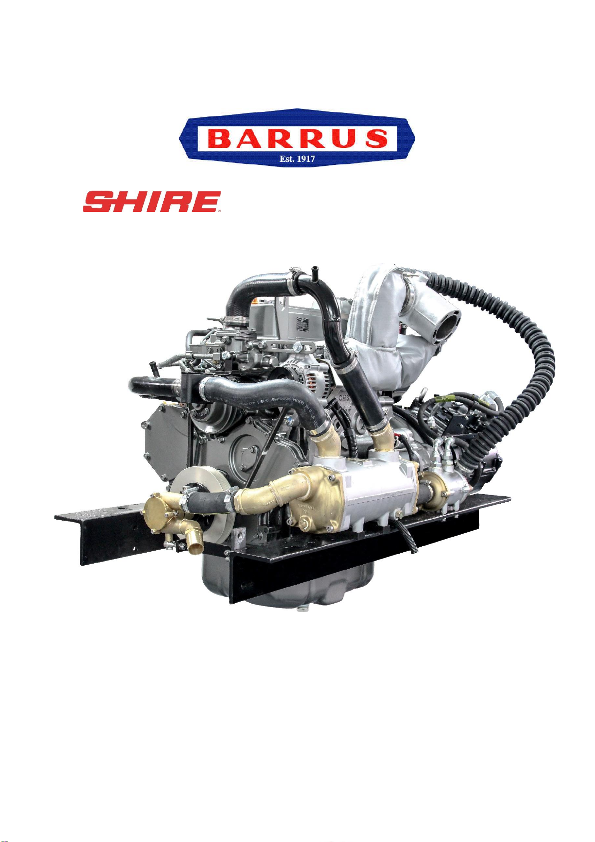
WORKBOAT ENGINE
MANUAL
For the following engine model*:
Shire 15 70WB
*Standard Model, there may be a number of optional extras, or alternative components, that
might be fitted to an engine that are not shown in this book.
RDG603A81 –Issue 2
Page 2 of 93
SAFETY
E.P. Barrus is concerned for your safety. We use safety statements throughout the manual
to call your attention to the potential hazards associated with the operation of your Shire
engine.
Follow the precautions listed throughout the manual before operation, during operation and
during servicing/maintenance procedures for your safety, the safety of others and to protect
the performance of your engine.
Safety alert symbol appears throughout the manual. It meansattention, be alert as your safety
is involved. Please read and follow the message that appears after the safety alert symbol.
NOTICE:
This indicates a situation which can cause damage to the
machine, personal property and/or the environment or cause the
equipment to operate improperly
CAUTION:
This indicates a hazardous situation which, if not avoided, could
result in minor or moderate injury.
WARNING:
This indicates a hazardous situation which, if not avoided, could
result in death or serious injury.
DANGER:
This indicates a hazardous situation which, if not avoided, will
result in death or serious injury.

RDG603A81 –Issue 2
Page 3 of 93
Engine Details
Engine Serial Number:
Please enter your engine serial number in the space provided above. Please quote the
engine identification number during any enquiry or when ordering spare parts. Information
about the engine serial number and its location on the engine can be found in SECTION 2 of
the manual.
Shire Engine Manuals and Shire Parts Books
To access the Shire Engine Manuals and Shire Parts Books on the internet type the
following short links into your search engine:
https://www.barrus.co.uk/shire-manuals/
https://www.barrus.co.uk/shire-parts/

RDG603A81 –Issue 2
Page 4 of 93
Operators Manual
NOTICE:
THIS MANUAL FORMS AN INTEGRAL PART OF THE ENGINE IT ACCOMPANIES, IF
A TRANSFER OF TITLE OCCURS, IT MUST ALWAYS BE HANDED OVER TO THE
NEW OWNER.
Thank you for purchasing this Shire Workboat Marine Engine from E.P.Barrus. This manual
has been compiled to help you to operate your engine and its associated parts with safety
and pleasure. Please read it carefully in conjunction with the Yanmar and PRM Gearbox
Manuals and familiarise yourself with the engine and its parts before operation. The PRM
Gearbox Manual is also available from the PRM website:
www.prm-newage.com
If the engine is fitted with an E-Kit and/or Hybrid options, please also read the supplied
manuals for them carefully.
The information and recommendations given in this manual are based on the latest
information available at the time of publication. E.P.Barrus reserve the right to change the
specification of its products and manuals without prior notice.
Depending upon the equipment specification of the engine and accessories fitted, there may
be discrepancies with the information presented in this handbook. No claims may be
pursued in this respect.

RDG603A81 –Issue 2
Page 5 of 93
WARRANTY
This UK Limited Warranty provides coverage for five (5) years (or 2000 hours whichever
occurs first) for recreational users and three (3) years (or 2000 hours whichever occurs first)
for commercial users from the date of warranty registration. The warranty is for non-
serviceable items. The repair or replacement of parts, or the performance of service under
this warranty, does not extend the life of this warranty beyond its original expiry date.
To ensure that you have been registered for your warranty, please ask your Boat Builder or
Engine Supplier to provide your portion of the registration form.
The Warranty will only apply if the following have been carried out:
1) The Installation Check List in the Installation Section has been fully completed.
2) The boat builder or engine installer has completed the Boat Builder Section on the Service
Record Card (located at the back of this manual) regarding hand over and commissioning of
boat.
E.P Barrus staff or their representatives can only carry out warranty repairs if
there is suitable access and room around the engine to work safely.
Failure to complete and return the registration form to E.P Barrus will result in
the warranty period starting from the date of engine manufacture NOT from the date
of purchase.
PRM Gearboxes are covered by a three (3) year warranty for recreation users and two (2)
years for commercial users.
Engine alternator, starter motor and electrical components are only covered by a one (1) year
warranty.
CONDITIONS THAT MUST BE MET IN ORDER TO OBTAIN WARRANTY COVERAGE
Warranty coverage is only available from an authorised dealer in the country in which the
sale occurred. Routine maintenance outlined in the Owner’s Manual must be performed using
genuine parts in order to maintain warranty coverage. If the customer performs maintenance,
Barrus reserves the right to make future warranty coverage possible only with proof of proper
maintenance.

RDG603A81 –Issue 2
Page 6 of 93
WARRANTY CLAIMS
Warranty claims shall be made by an authorised dealer or boat builder.
The dealer or boat builder will then arrange for the inspection and any necessary repairs. If
the repairs carried out are not covered by the warranty, the purchaser shall pay for all related
labour and material, and any other expenses associated with that service.
WHAT IS NOT COVERED
This limited warranty does not cover routine maintenance items, adjustments, normal wear
and tear, damage caused by abnormal use, operation of the product in a manner inconsistent
with the recommended operation/duty cycle section of the Owner’s Manual, accident,
submersion, improper installation (proper installation specification and techniques are set
forth in the Operations and First time running sections in this manual), use of an accessory
or part not manufactured or sold by us, or alteration or removal of parts. Expenses related
to crane-out, launch, towing, storage, telephone, rental, inconvenience, slip fees, insurance
coverage, loan payments, loss of time, loss of income, or any other types of accidental or
consequential damages are not covered by this warranty.
Engine electrical systems fitted with alternator boost charge systems or any other electrical
management systems are not covered by warranty.
Engine and fuel equipment is not covered by warranty if bio-diesel that does not comply with
EN15940 is used in the fuel system (See 5. Refuelling of Section 6 –Operation). Also, if
no type of water trap is incorporated into the fuel system.
Engine and engine starting systems are not covered by warranty if it is found that the engine
start battery is of the incorrect specification as stated in 1. Engine Data of Section 10 -
Technical Data.
Damage due to rust or corrosion, submersion, or unreasonable exposure to the environment,
such as exposure tohigh humidity, rain fall, orseawater, or conditions resulting in thefreezing
of cooling water are also not covered.
Engine and engine starting systems are not covered by warranty if it is found that the engine
start battery is either partially or fully discharged.
The standard alternators fitted to Shire engines are not suitable for charging lithium-ion
batteries. If the standard alternators are used for charging lithium-ion batteries, they will not
be covered under warranty. If lithium-ion batteries are to be used a specialist alternator will
be required.

RDG603A81 –Issue 2
Page 7 of 93
Index Page
SECTION 1 –Safety Precautions .....................................................................................11
1. General......................................................................................................................11
2. Lifting.........................................................................................................................11
3. Rotating Shafts and Belts ..........................................................................................11
4. Exhaust System.........................................................................................................12
5. Launching and Lifting Boats.......................................................................................12
6. Batteries.....................................................................................................................12
SECTION 2 –Engine Identification...................................................................................14
SECTION 3 –Component Identification...........................................................................15
1. Shire 70 Work Boat....................................................................................................15
SECTION 4 –Control Panel ..............................................................................................16
1. Standard Control Panel..............................................................................................16
2. Deluxe Control Panel.................................................................................................16
3. Control Panel Overview.............................................................................................17
4. Warning Light Procedure...........................................................................................17
5. Overall Dimensions of the Standard Control Panel....................................................19
6. Overall Dimensions of the Deluxe Control Panel.......................................................19
SECTION 5 –Installation...................................................................................................20
1. Ventilation..................................................................................................................20
2. Engine Beds ..............................................................................................................20
3. Engine Cooling Water Inlet and Outlet Hose Connections ........................................20
4. Pressurised Water Header Tank................................................................................20
5. Shaft Connection and Propeller Selection .................................................................21
6. Engine Anti-Vibration Mounts ....................................................................................21
7. Engine Alignment.......................................................................................................24
8. Engine Inclination ......................................................................................................24
9. Electrics.....................................................................................................................25
10. Electrical Options.......................................................................................................26

RDG603A81 –Issue 2
Page 8 of 93
11. Engine Oil..................................................................................................................26
12. Fuel............................................................................................................................26
13. Coolant ......................................................................................................................28
14. Control Cables...........................................................................................................29
15. Domestic Battery Bank ..............................................................................................29
16. Seawater Strainer......................................................................................................30
17. Control Panel.............................................................................................................30
18. Exhaust System.........................................................................................................31
19. Hydraulic Drive Transmissions ..................................................................................35
20. Hydraulic Pump Drive Option (Shire 70WB)..............................................................35
21. PRM 280DP Gearbox with Power Take Off (Option - RDG914A198)........................36
22. Engine Start Battery...................................................................................................36
23. Installation Check List................................................................................................37
SECTION 6 –Operation.....................................................................................................38
1. Starting the engine for the first time...........................................................................38
2. Starting Procedure.....................................................................................................38
3. Stopping Procedure...................................................................................................39
4. Full Load Running......................................................................................................39
5. Refuelling...................................................................................................................39
6. Diesel Fuel Additive...................................................................................................40
7. Single Lever Side Mount Operation - Optional (RDG9210055) .................................40
8. Shifting in and out of gear..........................................................................................40
SECTION 7 –Service Procedure ......................................................................................41
1. Engine Oil and Filter Change.....................................................................................41
2. Air Filter Check and Change......................................................................................42
3. Gearbox Oil Change..................................................................................................42
4. Disposal of Oil and Related Items..............................................................................43
5. Primary Fuel Filter Drain (RDG9188346)...................................................................44
6. Primary Fuel Filter Change........................................................................................45
7. Secondary Fuel Filter Change...................................................................................45

RDG603A81 –Issue 2
Page 9 of 93
8. Fuel System Bleeding................................................................................................46
9. Cooling System..........................................................................................................46
10. Belt Adjustment..........................................................................................................47
11. Belt Maintenance.......................................................................................................48
12. Belt Replacement ......................................................................................................48
13. Control Panel Maintenance........................................................................................49
14. Sacrificial Anode Change...........................................................................................50
15. Raw Water Pump Impeller Change ...........................................................................50
16. Engine Heat Exchanger Tube Stack Flushing ...........................................................50
17. Winterisation of Seawater Cooling System................................................................51
SECTION 8 –Service Schedule........................................................................................52
1. Specifications and Capacities....................................................................................52
2. Service Intervals........................................................................................................53
SECTION 9 –Wiring Diagrams .........................................................................................54
1. Engine Wiring Diagram Shire 70................................................................................54
2. Standard Control Panel Wiring Diagram....................................................................55
3. Deluxe Control Panel Wiring Diagram .......................................................................56
4. Prestolite 24 Volt 120 Amp Alternator Wiring Diagram ..............................................57
SECTION 10 –Technical Data ..........................................................................................59
1. Engine Data...............................................................................................................59
2. Return Diesel System................................................................................................59
3. Dry Weight of Engine Data ........................................................................................59
SECTION 11 –Fault Diagnosis.........................................................................................60
1. Failure Indicator Flashing Pattern..............................................................................60
2. Examples Of Fault Code Light Sequences................................................................60
3. Fault Codes ...............................................................................................................62
SECTION 12 –Dealer List .................................................................................................64
SECTION 13 –Shire Service Parts...................................................................................66
SECTION 14 –Afterlife Recycling ....................................................................................68

RDG603A81 –Issue 2
Page 10 of 93
SECTION 15 –Declarations..............................................................................................69
1. Declaration of Conformity for Recreational Craft Propulsion Engine with the
requirements of Directive 2013/53/EU.................................................................................69
2. Declaration of Conformity for Recreational Propulsion Engine with the requirements of
the Recreational Craft Regulations 2017 (UKCA Marking)..................................................70
3. Declaration of Incorporation of Partly Completed Machinery.....................................71
4. EU Declaration of Conformity with the Exhaust Emissions Requirements of Directive
2013/53EU...........................................................................................................................75
SECTION 16 –Lubricant Safety Data Sheets ..................................................................76
1. Golden Film Running In Oil........................................................................................76
2. Ground Force 10W-40...............................................................................................84
SECTION 17 –Shire Service Record Card.......................................................................93

RDG603A81 –Issue 2
Page 11 of 93
SECTION 1 –Safety Precautions
1. General
NOTICE:
NEVER PERMIT ANYONE TO OPERATE THE ENGINE WITHOUT PROPER
TRAINING.
It is the responsibility of the installer/operator to ensure that the finished installation complies
with CE Marking, UKCA Marking, relevant Health & Safety Requirements, the Recreational
Craft Directive and or any other legislative requirements before commissioning.
Ensure that the engine battery isolator switch is in the off position and the key removed from
the control panel before carrying out any maintenance or repairs.
2. Lifting
DANGER:
CRUSH HAZARD! NEVER STAND UNDER A HOISTED ENGINE. IF THE HOIST
MECHANISM FAILS, THE ENGINE WILL FALL ON YOU, CAUSING SERIOUS INJURY
OR DEATH.
The Lifting points supplied with the engine are for lifting the engine/gearbox only. A suitable
spreader bar must be employed to prevent over-stressing either bracket during any lift.
3. Rotating Shafts and Belts
WARNING:
SEVERE HAZARD! KEEP HANDS AND OTHER BODY PARTS AWAY FROM
MOVING/ROTATING PARTS. WEAR TIGHT FITTING CLOTHING AND KEEP YOUR
HAIR SHORT OR TIE BACK. REMOVE ALL JEWELLERY BEFORE COMMENCING
WORK. CHECK BEFORE STARTING THE ENGINE THAT ANY TOOLS OR RAGS
USED DURING MAINTENANCE HAVE BEEN REMOVED FROM THE AREA.
RDG603A81 –Issue 2
Page 12 of 93
The engine and its accessories are not intended to be put into operation until they are
integrated into the boat as a whole. No person should be in the engine compartment and the
engine cover or deck hatches should be closed whilst the engine is running.
4. Exhaust System
WARNING:
EXHAUST HAZARD! NEVER OPERATE ENGINE IN A BOATS ENGINE BAY
WITHOUT PROPER VENTILATION. NEVER BLOCK VENTS OR OTHER MEANS OF
VENTILATION. ALL COMBUSTION ENGINES CREATE CARBON MONOXIDE GAS
DURING OPERATION. ACCUMULATION OF THIS GAS COULD CAUSE ILLNESS OR
EVEN DEATH.
WARNING:
BURN HAZARD! WAIT UNTIL THE EXHAUST COOLS BEFORE YOU TOUCH IT.
Exhaust gases may have temperatures as high as 650°C and contain elements which are
harmful if ingested.
It is therefore essential that exhaust systems are gas tight and lagged to prevent accidental
burning and inhalation of exhaust gases when inside the boat cabin.
5. Launching and Lifting Boats
Care must be taken when launching or craning new boats into or out of the waterway, so that
water does not enter the engine via the exhaust system or air vents. It is recommended that
these are blocked temporarily whilst undertaking this procedure.
6. Batteries
DANGER:
EXPLOSION HAZARD! NEVER SHORT OUT THE BATTERY TERMINALS,
INCLUDING WHEN CHECKING THE REMAINING BATTERY CHARGE THIS WILL
RESULT IN A SPARK AND MAY CAUSE AN EXPLOSION OR FIRE.
RDG603A81 –Issue 2
Page 13 of 93
WARNING:
BURN HAZARD! BATTERIES CONTAIN SULPHURIC ACID. NEVER ALLOW
BATTERY FLUID TO COME IN CONTACT WITH SKIN, EYES OR CLOTHING. SEVERE
BURNS COULD RESULT. MAKE SURE THE CORRECT PERSONAL PROTECTION
EQUIPMENT IS WORN.
•Batteries can produce explosive gases; keep sparks andflames away from the battery.
NO SMOKING
•Batteries contain sulphuric acid; if splashed on skin or eyes, flush well with water and
seek medical advice.
•Keep battery tops and battery compartment ventilated at all times
•If disconnecting the battery; remove the earth lead FIRST; and re-connect it last.
•If charging the battery; ensure that the charger is switched off before connecting and
disconnecting.
•Do not tip the battery on its side.
•Please see label on battery or manufacturer’s instructions for specific information.
•Make sure the start battery fitted is of the correct recommended capacity as stated in
1. Engine Data of Section 10 - Technical Data. If an incorrectly sized battery in
fitted the ECU may not work and the engine may fail to start.
•Always make sure the start battery is fully charged. If the battery in not fully charged
the ECU may not work and the engine may fail to start.
RDG603A81 –Issue 2
Page 14 of 93
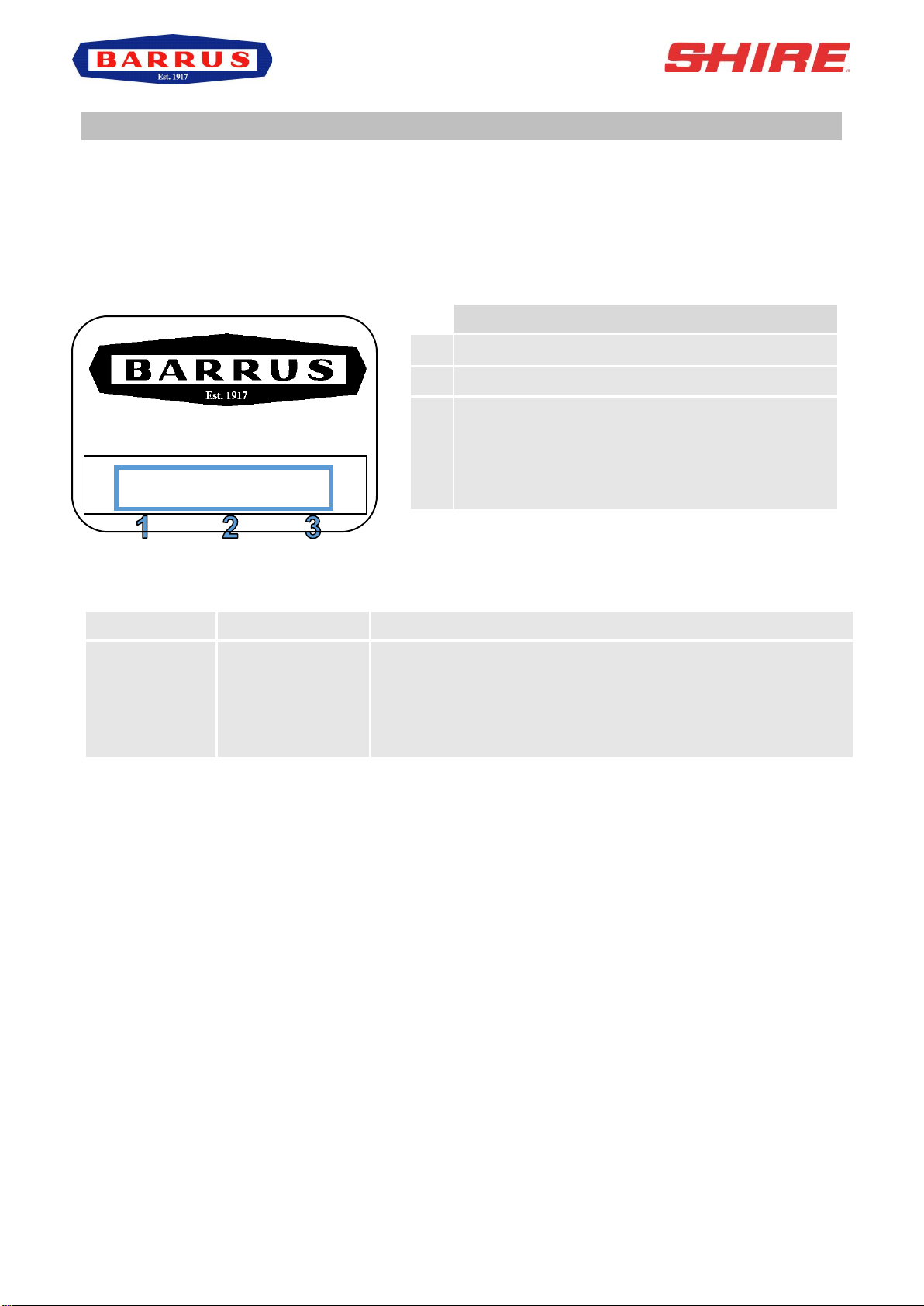
SECTION 2 –Engine Identification
The engine serial number can be found engraved into the brass plate on the top of the engine
rocker cover and stamped to the crankcase next to the starter motor.
An example of the engine identification plate is shown below (Figure 1):
Figure 1: Engine Identification Badge
Description of Models:
Abbreviation
Type of Engine
Description*
WB
Work Boat
Seawater/Heat Exchanger cooled, dry exhaust manifold
with either a dry exhaust system (same as a Canal Boat)
or water injected exhaust system. Can also be used for
sea going applications
*Note: There are a number of other optional extras that may be fitted to an engine that are
not listed here.
A list of common item service part numbers can be found in Section 13, Shire Service Parts.
Description
1
Engine Model
2
Serial Number
3
Indicates Model Type or Optional Extras:
WB = Work Boat
D = Deluxe Panel
3 = 3:1 Ratio Gearbox
SHIRE
70-XXXXX-D

RDG603A81 –Issue 2
Page 15 of 93
SECTION 3 –Component Identification
1. Shire 70 Work Boat
Figure 2: Shire 70 Work Boat Left Side (Viewed from front)
TO BE ADDED
Figure 3: Shire 70 Work Boat Right Side (Viewed from rear)
*Note: There are a number of other optional extras that may be fitted to an engine that are
not shown here.
Description*
1
Coolant Heat Exhanger
2
50 Amp 12 Volt Alternator
3
Seawater Pump (Crankshaft
Driven)
4
Gearbox Oil Cooler
Description*
5
Air Filter
6
Gearbox
7
Oil Filter
8
Primary Fuel Filter
9
Secondary Fuel Filter
10
Gearbox Drain Pump
11
Engine Sump Pump
RDG603A81 –Issue 2
Page 16 of 93
SECTION 4 –Control Panel
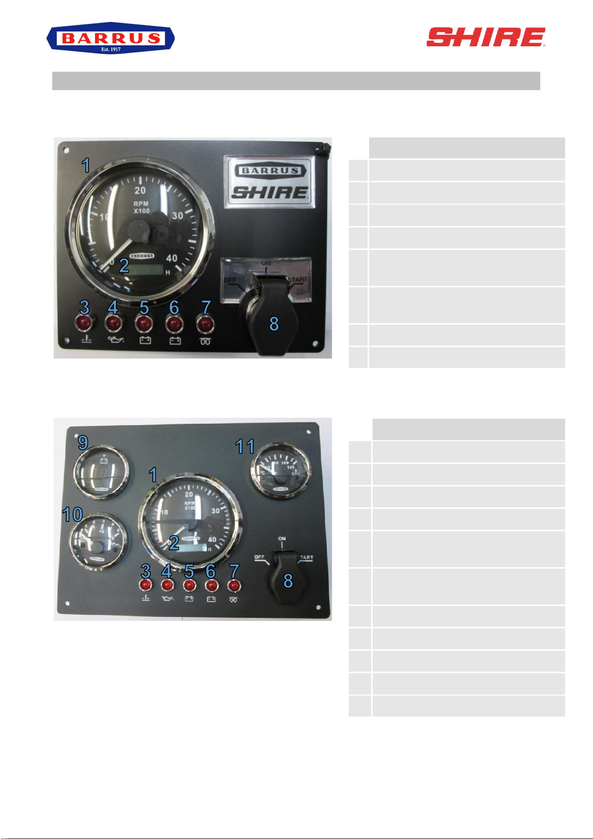
1. Standard Control Panel
Figure 4: Standard Control Panel
2. Deluxe Control Panel
Figure 5: Deluxe Control Panel
Description
1
Tachometer Gauge
2
Hour Meter
3
Water Temperature Warning Light
4
Oil Pressure Warning Light
5
50A Alternator Charge Warning
Light
6
150/240A Alternator Charge
Warning Light
7
Glow Plug Light
8
Key Flap and Ignition Switch
Description
1
Tachometer Gauge
2
Hour Meter
3
Water Temperature Warning Light
4
Oil Pressure Warning Light
5
50A Alternator Charge Warning
Light
6
150/240A Alternator Charge
Warning Light
7
Glow Plug Light
8
Key Flap and Ignition Switch
9
50A Alternator Output Gauge
10
Oil Pressure Gauge
11
Water Temperature Gauge

RDG603A81 –Issue 2
Page 17 of 93
3. Control Panel Overview
•All Shire engines are supplied with a control panel.
•Depending on the model of Shire engine, the control panel will either be a standard
control panel or a deluxe control panel. The following table shows which panel comes
with each type of engine as standard. Please note that on certain Shire engines a
different type of control panel can be ordered as an option.
Engine
Control Panel Supplied*
Shire 70 Work Boat
Deluxe Control Panel
* Panel supplied as standard. On certain engines a different control panel may be supplied
as an option.
4. Warning Light Procedure
•When the ignition is first turned on, the control panel warning lights will come on as a
bulb check. When the engine is started the warning lights will go out. Please note that
the water temperature warning light and glow plug light operate slightly differently.
•The water temperature warning light will only come on for a brief period of time when
the ignition is first turned on as a bulb check. It will then only illuminate in the case of
the engine coolant temperature exceeding the maximum safety level.
•The glow plug light will come on when the ignition is first turned on for 5 –8 seconds
to indicate the heating system is operational. When the light goes out the engine can
be started.
•Whilst the control panel is in operation all the gauges are backlit. This does not indicate
a fault and is a normal function for the control panel.
•If any of the warning lights on the control panel come on whilst the engine is running,
please follow the correct procedure as shown in the following table.
In the event of a fault, only trained and qualified personnel should undertake
repairs on the engine

RDG603A81 –Issue 2
Page 18 of 93
Description
Procedure for Warning Light
1
Tachometer Gauge
-
2
Hour Meter
-
3
Water Temperature Warning Light
Reduce the engine revs and stop the engine
within one or two minutes. Check the coolant
level (refer to 9. Cooling System of SECTION 7
- SERVICE PROCEDURE). If the coolant level is
incorrect, fill it to the correct level (refer to 9.
Cooling System of SECTION 7 - SERVICE
PROCEDURE)and restart the engine. If the
coolant level is correct and the fault is still
present, or there is a coolant leak, please contact
your local dealer.
4
Oil Pressure Warning Light
Stop the engine immediately. Contact your local
dealer. Failure to stop the engine may result in
permanent engine damage.
5
50A Alternator Charge Warning
Light
This indicates that the alternator has stopped
charging. The engine can still be operated for a
short period of time. Contact your local dealer.
6
150/240A Alternator Charge
Warning Light*
This indicates that the alternator has stopped
charging. The engine can still be operated for a
short period of time. Contact your local dealer.
7
Glow Plug Light
This indicates that the cold start system is
operating. If the light fails to illuminate during the
starting procedure contact your local dealer.
8
Key Flap and Ignition Switch
-
9
50A Alternator Output Gauge
-
10
Oil Pressure Gauge
-
11
Water Temperature Gauge
-
*Only applicable if a second alternator is fitted to the engine
RDG603A81 –Issue 2
Page 19 of 93
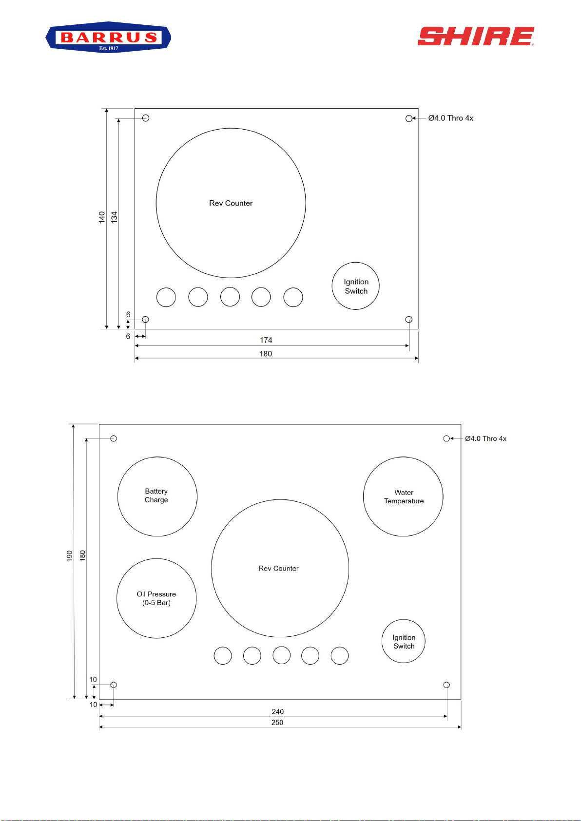
5. Overall Dimensions of the Standard Control Panel
(All Dimensions are in mm)
Figure 6: Standard Control Panel Dimensions
6. Overall Dimensions of the Deluxe Control Panel
(All Dimensions are in mm)
Figure 7: Deluxe Control Panel Dimensions

RDG603A81 –Issue 2
Page 20 of 93
SECTION 5 –Installation
NOTICE:
REFER TO THE SHIRE AND YANMAR MANUALS PRIOR TO INSTALLING THE
ENGINE.
1. Ventilation
•All internal combustion engines radiate heat and require cool, clean air to aid complete
combustion.
•Please ensure that adequate engine room ventilation is provided, by fitting at least two
vents of an aperture of not less than 15,000mm2each (24in2).
An allowance must be made for any grills, louvres or bends placed in the
airflows and generally an increase of 25% in area is sufficient to overcome any
restriction problems.
2. Engine Beds
•These should be a minimum of 10mm thick, extended rearward and be welded to the
hull and forward to the bulkhead. Webs or gussets must be welded in place midway
to prevent flexing.
3. Engine Cooling Water Inlet and Outlet Hose Connections
•The connections are on the right hand (starboard) side of the engine.
•Use 100mm ID suitable machine flexible exhaust hose. Do not step down to a smaller
size.
•Use a good quality hose that cannot collapse or kink and is capable of working at
temperatures in excess of 100°C.
4. Pressurised Water Header Tank
WARNING:
SCALD HAZARD! NEVER REMOVE THE HEADER TANK CAP IF THE ENGINE IS
HOT. STEAM AND HOT COOLANT MAY SPURT OUT AND CAUSE INJURY. TIGHTEN
THE HEADER TANK CAP SECURELY AFTER BEING REMOVED. STEAM CAN
SPURT OUT DURING ENGINE OPERATION IF THE CAP IS LOOSE.
Table of contents
Other Barrus Outboard Motor manuals


