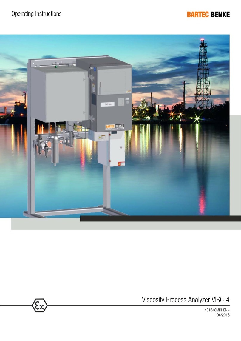
BARTEC BENKE CFPP-4.2 User manual

CFPP Process Analyzer CFPP-4.2
Operating Instructions
395778MDHEN A
03/2016

BARTEC BENKE GmbH
Borsigstraße 10
21465 Reinbek
Germany
Tel.: +49 (0) 40 - 72703 - 0
Fax: +49 (0) 40 - 72703 - 363
E-Mail: service@bartec-benke.de
© 2016 BARTEC BENKE GmbH, Reinbek. All rights reserved.
These operating instructions are subject to copyright laws. This document may not be
reproduced or transmitted, neither whole nor in parts, by any electronic, mechanical or
other means, without prior written permission from BARTEC BENKE GmbH. Nor is
production of the entire instrument or individual components permissible on the basis of
these operating instructions without our written approval.

Contents I
03/2016 CFPP Process Analyzer CFPP-4.2
Contents
1General................................................................................................5
1.1 About this Document..........................................................................................6
1.2 Liability and Warranty.........................................................................................6
2Safety...................................................................................................7
2.1 General...............................................................................................................8
2.2 Intended Use......................................................................................................8
2.3 Safety Symbols and Signal Words.....................................................................9
2.4 Explosion Protection.........................................................................................10
2.4.1 Labeling on the Analyzer.......................................................................10
2.4.2 Types of Protection and certificates......................................................12
2.4.3 Ensuring and Maintaining Explosion Protection ...................................14
2.5 Protective Devices............................................................................................14
2.6 Personnel .........................................................................................................17
2.7 Personal Protective Equipment........................................................................18
2.8 Potential Dangers and Risks............................................................................18
2.9 In Case of an Accident or Emergency..............................................................22
3Introduction.......................................................................................23
3.1 The CFPP Process Analyzer CFPP-4.2...........................................................24
3.2 Significance of the Cold Filter Plugging Point..................................................25
3.3 Measuring Principle..........................................................................................25
4Technical Data..................................................................................27
5Analyzer Description........................................................................31
5.1 Overview and Operating Elements...................................................................32
5.2 Type plates.......................................................................................................34
5.3Analyzer Components......................................................................................35
5.3.1 Measuring unit enclosure......................................................................35
5.3.2 Measuring cell.......................................................................................37
5.4 Control box.......................................................................................................38
5.5 Sample conditioning system (optional) ............................................................39
5.6 Further Options.................................................................................................40
6Transport, Packaging and Storage .................................................41
6.1 Transport..........................................................................................................42
6.2 Delivery.............................................................................................................43
6.3 Intermediate Storage........................................................................................43
6.4 Packaging.........................................................................................................43

II Contents
CFPP Process Analyzer CFPP-4.2 03/2016
7Installation and Disassembly.......................................................... 45
7.1 Installation........................................................................................................ 46
7.1.1 Operating Area Requirements.............................................................. 46
7.1.2 Assembly of the Sample Conditioning System (Optional) ................... 46
7.1.3 Securing the Analyzer .......................................................................... 47
7.1.4 Tubing Connections ............................................................................. 48
7.1.5 Electrical Connections.......................................................................... 49
7.2 Disassembly .................................................................................................... 51
7.2.1 Disconnecting Electrical Connections.................................................. 51
7.2.2 Removing Tubing Connections ............................................................ 52
7.3 Disposal........................................................................................................... 52
8Initial Operation................................................................................ 53
8.1 Putting the Analyzer into Operation................................................................. 54
8.2 Flushing the Product Feed Line....................................................................... 54
8.3 Initial Operation of the Sample Conditioning System (Optional)..................... 57
8.4 Feeding In Product .......................................................................................... 59
8.5 Connecting the Analyzer to Instrument Air Supply.......................................... 60
9Operation.......................................................................................... 63
9.1 Switching on the Analyzer ............................................................................... 64
9.2 Operation......................................................................................................... 65
9.3 Switching off the Analyzer ............................................................................... 65
9.3.1 Switching off in Normal Operation........................................................ 65
9.3.2 Switching off in an Emergency............................................................. 66
10 Maintenance..................................................................................... 67
10.1 Safety during Maintenance.............................................................................. 68
10.1.1 Qualification of Personnel .................................................................... 68
10.2 Measures after Maintenance........................................................................... 69
10.3 Maintenance and Inspection Plan ................................................................... 69
10.4 Checking the Protective Devices..................................................................... 70
10.5 General Visual Inspection................................................................................ 72
10.6 Visual Inspection Inside Measuring unit enclosure ......................................... 73
10.7 Checking the residual-current device (RCD)................................................... 75
10.7.1 Measures after the RCD has triggered ................................................ 75
10.7.2 Measures in case of troubles ............................................................... 76
10.8 Checking the Test Filter................................................................................... 77
10.9 Cleaning the touchscreen................................................................................ 78
10.10 Changing the battery of the box PC ................................................................ 79
10.11 Checking for product and emptying vacuum tank ........................................... 81
10.12 Removing the Measuring Cell ......................................................................... 82
10.13 Cleaning the Test Filter.................................................................................... 86
10.14 Checking Liquid Level in the Sample Container.............................................. 89

Contents III
03/2016 CFPP Process Analyzer CFPP-4.2
10.14.1 Checking the Liquid Level in the Sample Container ........................89
10.14.2 Adjusting the Liquid Level in the Sample Container ........................93
10.15 Reinstalling the Measuring Cell........................................................................94
10.16 Remove the cover of the measuring cell housing............................................97
10.17 Install the cover on the measuring cell housing...............................................99
11 Troubleshooting .............................................................................101

IV Contents
CFPP Process Analyzer CFPP-4.2 03/2016

General 5
03/2016 CFPP Process Analyzer CFPP-4.2
1 General

6 General
CFPP Process Analyzer CFPP-4.2 03/2016
1.1 About this Document
These operating instructions are intended for personnel with a basic technical knowledge
of instruments such as the one described here. If you have little or no experience working
with such instruments, we recommend that you get advice from experienced persons or
take part in a training course by BARTEC BENKE before using the instrument.
These operating instructions must always be kept with the analyzer and must be
accessible at any time. They are an integral part of the analyzer.
Should you sell the analyzer, you must pass on the operating instructions to the next
owner. If you receive supplements to the operating instructions from BARTEC BENKE, you
must add them to the original document.
In addition to these operating instructions, all documents apply which are listed in the
table of contents of the customer file. You must observe the instructions in these
documents, particularly the safety instructions in the operating instructions for analyzer
components.
These operating instructions do not state the duties of the operating company which are
stated in the applicable laws, regulations and technical standards (e.g. organizational
measures, explosion protection document, regular checks, etc.).
For translations of these operating instructions into other languages, the German version is
to be regarded as the original document.
1.2 Liability and Warranty
Read these operating instructions carefully before installation and startup of the
instrument and observe the safety precautions. BARTEC BENKE cannot accept liability for
injuries or damages caused by failure to observe the operating instructions and safety
precautions.
We have checked the information in this document carefully to ensure its completeness
and correctness. However, as alterations may occur due to technical improvements, we
cannot accept liability for complete consistency. These operating instructions do not
constitute any obligation or guarantee of performance on the part of BARTEC BENKE.

Safety 7
03/2016 CFPP Process Analyzer CFPP-4.2
2 Safety

8 Safety
CFPP Process Analyzer CFPP-4.2 03/2016
This chapter gives you an overview of the most important safety issues.
2.1 General
The analyzer may be dangerous if the safety instructions are not observed, or if the
analyzer is used for purposes for which it is not intended, or if it is operated by unqualified
personnel.
Make sure that any person working with the analyzer has first read and understood the
operating instructions. This is also necessary if the person has worked with a similar
analyzer before or has been trained for this purpose.
Also observe the detailed safety instructions in the individual chapters. They are
highlighted with signal words and symbols. In addition, observe the notes and instructions
on the instrument and keep them readable. Also observe the safety instructions in the
supplied operation manuals of all built-in equipment and components. Observe the
information on operation, maintenance and servicing.
2.2 Intended Use
The CFPP Process Analyzer CFPP-4.2 is designed for determining in a fully automated
process the temperature limit value for the filterability of liquid petrochemical products. A
sample stream and a calibration stream (optional) can be connected to the analyzer, which
operates online. It is intended to monitor the quality of production in the process and also
the compliance with mandatory specifications for petrochemical products.
The analyzer is intended exclusively for stationary operation in an analysis building.
The analyzer may only be used for products which correspond to the specification defined
at the time of ordering.
The analyzer is designed for operating in zones 1 and 2 of potentially explosive areas
caused by gases. Make sure that no other gases (e.g. hydrogen or oxygen used by other
analyzers) and no other vapors or liquids can reach the analyzer through the vent- drain-
system (vent = waste gas outlet; drain = waste liquid outlet).
It is not permissible to make any technical modifications to the analyzer without written
authorization from BARTEC BENKE.
Use only spare parts supplied by BARTEC BENKE.

Safety 9
03/2016 CFPP Process Analyzer CFPP-4.2
2.3 Safety Symbols and Signal Words
In this document, safety instructions are highlighted by signal words and safety symbols.
The following signal words are used for safety instructions:
DANGER! indicates an imminently hazardous situation which will very likely result in
death or serious injury if the safety instructions are not observed.
WARNING! indicates a potentially hazardous situation which could result in death or
serious injury if the safety instructions are not observed.
CAUTION! indicates a potentially hazardous situation which may result in minor or
moderate injury if the safety instructions are not observed.
ATTENTION! indicates that the analyzer may be damaged or may malfunction if the
safety instructions are not observed.
The signal words DANGER!, WARNING! and CAUTION! are used with triangular
symbols which state the type of hazard, for example:
General hazard
Dangerous electric current
Potentially explosive atmosphere
Hazardous
substances
Coldness
Hot surface
s
The following symbol is used with the signal word ATTENTION!:
!

10 Safety
CFPP Process Analyzer CFPP-4.2 03/2016
2.4 Explosion Protection
2.4.1 Labeling on the Analyzer
The analyzer is designed for operation in explosion hazard areas. It is labeled as follows:
II 2 G IIC T4 Gb
The labeling gives you the following information:
Labeling Meaning
II Equipment group: The analyzer may be used in places likely to
become endangered by explosive atmospheres, except
underground (mining).
2 G Equipment category: The figure 2 means that an explosive
atmosphere may occur occasionally. The analyzer ensures a high
level of protection and may be used in zones 1 and 2.
The letter G means that the flammable substances which cause the
explosive atmosphere may be gas, mist or vapor (but not dust).
IIC Gases and vapors which form an explosive atmosphere are
classified by their explosion characteristics in the subgroups IIA, IIB
or IIC. In this case, gases and vapors of the subgroups IIC are
permitted.
T4 Gases and vapors which form an explosive atmosphere are
classified by their ignition temperature in the temperature classes
T1 to T6. In this case, gases and vapors in the temperature classes
T1 to T4 (ignition temperature >135°C according to IEC 60079-4)
are permitted. These are for example gasoline, diesel fuel,
hydrogen sulfide and hydrogen.
The maximum surface temperature of the analyzer is <135°C.
Gb Gb: The device ensures a high degree of safety. It can be used in
zone 1 and in zone 2. A potentially explosive atmosphere may
occasionally occur.

Safety 11
03/2016 CFPP Process Analyzer CFPP-4.2
For use in the American region the analyzer is marked additionally according to the
National Electrical Code NEC 500 of the USA respectively the Canadian Electrical Code
CEC J18:
Class I, Division 2, Groups B, C, D, T4
The labeling gives you the following information:
Labeling Meaning
Class I Classification of potentially explosive atmospheres in classes 1
(combustible gases, vapors and mist), 2 (dusts) and 3 (fibers and
lint). The device may be used in class 1 potentially explosive areas.
Div 2 Classification of potentially explosive areas in divisions 1 and 2
according to the frequency in which potentially explosive
atmospheres arise.
In division 2, hazardous concentrations of combustible gases,
vapors and mist do not usually occur under normal operating
conditions. The device may be used in such areas.
Group A, B, C, D Classification of gases, vapors and mists into the groups
A (acetylene), B (hydrogen), C (ethylene) and D (propane).
The device provides explosion protection for groups B, C and D.
T4 Classification of gases and vapors depending on their ignition
temperature into the classes T1 to T6 (in accordance with IEC
60079-4). The device has been designed for use with gases and
vapors of temperature class:
T4: 135 °C < ignition temperature < 200 °C

12 Safety
CFPP Process Analyzer CFPP-4.2 03/2016
2.4.2 Types of Protection and certificates
The analyzer and its components conform to different types of protection which are
defined as follows:
Pressurized enclosure „p“
The surrounding potentially explosive atmosphere is prevented from entering the
measuring unit enclosure by means of an ignition shield gas (in this case: air) which is
held inside the enclosure and kept at a higher pressure than the surrounding atmospheric
pressure.
Flameproof enclosure “d”
Type of protection where components which could ignite an explosive atmosphere are
built into an enclosure. The enclosure is designed to withstand the pressure of an
explosion inside the enclosure and to prevent the transmission of the explosion to the
explosive atmosphere surrounding the enclosure.
Increased safety “e”
An increased safety level is achieved by additional measures. This eliminates the risk of
incorrectly high temperatures and the risk of sparks or electric arcs inside and on the
surface of electrical components which do not constitute an ignition source during normal
operation.
Encapsulation “m”
Components which could ignite an explosive atmosphere by sparks or heat are potted so
as to prevent ignition of the explosive atmosphere. This is achieved by encapsulating the
components in a compound resistant to physical and chemical influences.
Intrinsic safety “i”
Intrinsically safe circuits are circuits in which no spark or thermic effect can ignite an
explosive atmosphere of the subgroups IIA, IIB or IIC.

Safety 13
03/2016 CFPP Process Analyzer CFPP-4.2
The device is essentially made up of main subassemblies, which are installed in the
following boxes:
Housing Types of protection
Control box p
Measuring cell housing p
Power supply box e
Signal junction box e
Measuring unit enclosure not required
The explosion-proof boxes and their installations have been ATEX-certified as individual
subassemblies. All components relevant for explosion protection outside the control box
and measuring cell housing are protected against explosions by their own ignition
protection class. Electrical equipment inside the measuring unit enclosure and the
thermostat for the optional chiller are operated out of the control box in intrinsically safe
electrical circuits.
Note: The list with explosion-proof components or subassemblies used and the
corresponding certificates can be found in your customer folder.
The risk assessment shows that no additional ignition hazards arise from the combination
of the explosion protect components and subassemblies. For this reason the device does
not require an assessment as an electrical device according to ATEX. The conformity
assessment process has been checked by a notified body and has been approved via a
statement of conformity.

14 Safety
CFPP Process Analyzer CFPP-4.2 03/2016
2.4.3 Ensuring and Maintaining Explosion Protection
•The explosion protection system of the analyzer is designed for the
technical characteristics of the substances which were specified at the time
of ordering the analyzer. Before you switch on the analyzer, and while the
analyzer is operating, make sure (e.g. by de-airing the lines carefully) that
the product feed lines and all lines carrying product contain only the
specified product. Also make sure that the product properties correspond to
the specification.
•Make sure that no other gases (e.g. hydrogen or oxygen used by other
analyzers) and no other vapors or liquids can reach the analyzer through
the vent-drain-system (vent = waste gas outlet; drain = waste liquid
outlet).
•It is not permissible to make any technical modifications to the analyzer
without written authorization from BARTEC BENKE. Any unauthorized
modification can impair the safety of the analyzer and lead to accidents.
•Use only spare parts supplied by BARTEC BENKE.
2.5 Protective Devices
The protective devices are required for safe operation of the analyzer.
In addition to the protective devices described above, there are numerous other
components and electrical equipment required for safe operation. Particularly, there are
several individual electrical components which conform to different types of protection. For
further information, please refer to chapter 2.4.

Safety 15
03/2016 CFPP Process Analyzer CFPP-4.2
The analyzer is equipped with the following protective devices:
12
3
4
5
7
8
9
10
11
10
12
18 14
15
16
17
1
14
20
21
22
13
23
6
19
Fig. 2.1: Protective Devices
1 Warning label “Clean plastics”
2 Label for key switch
3 Key switch
4 Control box
5 Signal junction box with cover
6 Lock for double-bit key
7 Power supply box
8 Upper cover of Chiller for Liquids
9 Housing and front cover of
Chiller for Liquids
10 Locks of control box
11 Warning label “Opening the
housing”
12 Door of control box
13 Rear cover of Chiller for Liquids
14 Warning label “Electrical
equipment” (lightning symbol)
15 Warning label “Coldness”
16 Locks of measuring cell housing
17 Measuring cell housing
18 Warning label “Opening the
housing”
19 Cover of measuring cell housing
20 Warning label “Hot surfaces”
21 Warning label “Fluids under
pressure”
22 Mandatory-sign “Wear protective
goggles”
23 Mandatory-sign “Wear protective
gloves”

16 Safety
CFPP Process Analyzer CFPP-4.2 03/2016
Control box and measuring cell housing
The control box (4) and the measuring cell housing (17) are pressurized (p). The housings
are connected by a flushing pipe.
By means of the key switch (3) ("bypass switch"), you can activate or deactivate the
explosion protection (overpressure monitoring) for the housings. Above the key switch
there is a label (2) explaining the key switch positions.
During normal analyzer operation (explosive atmosphere may be present), the key
switch (3) must be in position “Explosion protection ON”. The position “Explosion
protection OFF” is only intended for service tasks. In that case, you must make sure that
there is no explosive atmosphere.
The touchscreen is made of plastic. If you rub the touchscreen with a dry cloth, sparks can
occur caused by static electricity discharge. If there is an explosive atmosphere present,
this can cause an explosion. Therefore, never clean the touchscreen with a dry cloth, but
always with a damp cloth. The warning label (1) indicates this.
The control box (4) and the measuring cell housing (17) contain equipment without
individual flame protection, i.e. potential ignition sources. In addition, the housings ensure
protection against contact and foreign matter as well as protection against moisture, and
thus prevent damage to the electrical equipment. Therefore, the door (12) of the control
box and the cover (19) of the measuring cell housing must be closed during normal
analyzer operation and locked by means of the locks (10 and 16). Even after the power is
switched off, the housings may be opened only after a waiting period of 5 minutes. This is
necessary because there may be components under electric charge and with high
temperature, i.e. potential ignition sources. The waiting period allows time for electric
charges to decrease and for hot components to cool down. The warning labels (11, 18)
indicate these risks.
Junction boxes
The power supply box (7) contains the terminals for connecting the power supply,
contactors and the APEX control unit. It is required for the pressurization of the control
box and the measuring cell housing. The control unit controls and monitors the flow rate
of the protective gas and the inner box pressure during rinsing. During operation, only the
inner box pressure is monitored. During operation, the control unit activates the voltages
via the contactors.
The power supply box is open and closed using a double-bit key. Explosion protection is
provided for the power supply box by the increased safety ignition protection (e) in closed
condition only. Therefore keep the power supply box closed during normal operation.
The signal junction box (5) contains terminals for connecting the signal lines. Explosion
protection is provided for the signal junction box by the increased safety ignition
protection (e) in closed condition only. Therefore keep the cover of the signal junction box
closed with all fastening bolts during normal operation.

Safety 17
03/2016 CFPP Process Analyzer CFPP-4.2
Chiller for Liquids
The housing of the chiller for Liquids (9) with its removable covers (8, 9, 13) ensures
protection against contact and foreign matter as well as protection against moisture, and
thus prevents damage to the electrical equipment. The upper cover (8) is fastened with
screws. You can remove the front cover (9) easily with a key. The covers must be closed
during normal analyzer operation.
Note: Further information to the Chiller for Liquids you find in the provided manual
for the Chiller for Liquids.
Labeling
The mandatory-signs (22, 23) in the measuring unit enclosure indicate that you must wear
protective goggles and protective gloves while you work in the measuring unit enclosure.
The warning labels (14 respectively 20) indicate that the measuring unit enclosure
contains electrical equipment respectively units with hot surfaces. The warning label (15)
indicates that the measuring cell housing contains actuated units with very cold surfaces.
Before opening the measuring cell housing wait always for warming up of the units in the
measuring cell housing.
You must check the protective devices at regular intervals. For further
information, please refer to chapter 10.4. The protective devices must never be
removed, bypassed or made unusable in any way. The warning labels must be
kept easily readable. Spare warning labels are available from BARTEC BENKE.
2.6 Personnel
Personnel working with the analyzer must be trained, authorized and instructed,
particularly with respect to possible hazards. Personnel must be qualified for the task. Due
to their training, experience and knowledge, particularly of applicable regulations, qualified
persons can assess and thus avoid the potential risks of a task.
Persons who carry out checks and maintenance work on the analyzer must be qualified
according to EN 60079-17 / IEC 60079-17.

18 Safety
CFPP Process Analyzer CFPP-4.2 03/2016
2.7 Personal Protective Equipment
When you carry out work on the analyzer, you must wear the following protective
equipment:
•Protective clothing
•Protective goggles
When dealing with dangerous substances, e.g. during maintenance work, you must wear
the following additional equipment:
•Appropriate protective gloves (see safety data sheet for the particular
substance)
•Appropriate breathing protection, if required, according to the safety
data sheet for the particular substance
For further information, please refer to the safety data sheet for the respective substance.
2.8 Potential Dangers and Risks
The analyzer conforms to the current state of the art. However, there is still a remaining
risk.
The analyzer operates with electrical power.
DAN
GER!
Dangerous electric current!
If you touch components carrying electric current, the electrical power can
cause serious injury or death.
FOR THIS REASON:
-Before cleaning or carrying out maintenance or repair work, switch
off all main control switches and secure them, so that the system
cannot be switched on accidentally.
-Work on electrical equipment must be carried out by qualified
personnel according to chapter 2.6.
-Do not remove or disable any protective devices.
Table of contents
Other BARTEC BENKE Measuring Instrument manuals

BARTEC BENKE
BARTEC BENKE DPA-4.5 User manual

BARTEC BENKE
BARTEC BENKE HYGROPHIL HCDT Series User manual

BARTEC BENKE
BARTEC BENKE HYGROPHIL H 4230-12 Ex Zone II User manual

BARTEC BENKE
BARTEC BENKE VISC-4 User manual

BARTEC BENKE
BARTEC BENKE A Series User manual

BARTEC BENKE
BARTEC BENKE HYGROPHIL F 5673 User manual

BARTEC BENKE
BARTEC BENKE RVP-4 User manual

BARTEC BENKE
BARTEC BENKE VOLUTANK PETRO 3003 User manual