BARTEC BENKE HYGROPHIL HCDT Series User manual

BARTEC BENKE GmbH Schulstraße 30 D 94239 Gotteszell Germany Telefon +49(0)9929)-301-0 Telefax +49(0)9929)-301-112
E-Mail: gotteszell@bartec-benke.de Internet: www.bartec-benke.de
Measuring systemfor determining the dew point of hydrocarbons in natural gas
天然气烃露点测量系统
Operating manual 操作手册
Software version 1.8.x
387897MDHEN
HCDT Series A


Contents
C - 1
HYGROPHIL® F 5673 Operating manual, Software version 1.8.x, 387897MDHEN (2013/4/26)
Contents
Contents Page Issue date
1System description_______________________________________________1-1
1.1 Measurement principle, Function and applications ______________________1-1 09.11.2011
1.2 Declaration of Conformity___________________________________________1-3 19.05.2011
1.3 Layout of the humidity measurement system___________________________1-5
1.3.1 Operator controls and display elements _______________________________1-5
1.3.1.1 Keyboard ________________________________________________________1-6
Key functions_____________________________________________________1-6 26.04.2013
1.3.1.2 Display __________________________________________________________1-8 17.03.2011
1.3.2 Interfaces________________________________________________________1-9 17.04.2013
1.4 Technical data___________________________________________________1-13
1.4.1 Evaluation unit F 5673 ____________________________________________1-13
1.4.2 CPU plug-in unit type 5673-113_____________________________________1-15
1.4.3 Power supply plug-in unit DC 10..36V type 5673-108___________________1-15 19.05.2011
1.4.4 Power supply plug-in unit AC 100..240V type 5673-109_________________1-15
1.4.5 HCDT-sensor plug-in unit type 5673-106 _____________________________1-16
1.4.6 Analog I/O Ex type 5673-114_______________________________________1-17 19.05.2011
1.4.7 Interface module type 5673-110 ____________________________________1-18 17.04.2013
1.4.8 Relay-Interface module type 5673-115_______________________________1-20 19.05.2011
1.4.9 Polychromator plug-in unit type 5673-302 ____________________________1-21
1.4.10 Humidity sensor L1661____________________________________________1-21 17.04.2013
1.4.11 HCDT sensor type 1510-11 ________________________________________1-23 17.04.2013
1.4.12 Power Supply type 1510-100_______________________________________1-25 17.04.2013
1.4.13 Power Supply type HCDT 1510-101 _________________________________1-27
1.4.14 Power Supply type HCDT 1510-102 _________________________________1-28 28.04.2011
1.5 Spare parts, accessories __________________________________________1-29 17.04.2013
2Safety precautions _______________________________________________2-1
3Installation ______________________________________________________3-1
3.1 General _________________________________________________________3-1
3.2 Arrangements for EMC_____________________________________________3-1
3.3 Sensor L166x ____________________________________________________3-2
3.3.1 Wiring the sensor L166x____________________________________________3-2 17.04.2013
3.3.2 Installing the sensor L166x _________________________________________3-6 28.04.2011
3.3.3 Installation advice _________________________________________________3-7 19.05.2011
3.4 HCDT Sample system types 5985-7x/8x/9x____________________________3-9 02.11.2011
3.4.1 Drawings _______________________________________________________3-10 17.04.2013
3.4.2 Wiring__________________________________________________________3-16 17.04.2013
Wiring the power supply type 1510-100 ______________________________3-18
Wiring the power supply type 1510-101 ______________________________3-20 04.06.2012
Wiring the power supply type 1510-102 ______________________________3-22 02.11.2011
HCDT- sensor cable 20...200 m ____________________________________3-23 17.04.2013
HCDT- sensor cable <20 m ________________________________________3-27 17.04.2013
3.4.3 Connections and initial operation ___________________________________3-31
3.4.3.1 Connections_____________________________________________________3-31
Gas____________________________________________________________3-31
Electronics______________________________________________________3-32
3.4.3.2 Settings ________________________________________________________3-32
Gas____________________________________________________________3-32
Peltier-cooling ___________________________________________________3-32
3.4.3.3 Initial operation __________________________________________________3-32

Contents
C - 2
HYGROPHIL® F 5673 Operating manual, Software version 1.8.x, 387897MDHEN (2013/4/26)
Contents Page Issue date
4Operation _______________________________________________________4-1
4.1 Start up__________________________________________________________4-1
4.2 Automatic sensor equalizing ________________________________________4-1 02.11.2011
4.3 Display modes ____________________________________________________4-3 17.03.2011
4.3.1 Combined display _________________________________________________4-4
4.3.1.1 Selecting a line ___________________________________________________4-4
4.3.1.2 Assigning a measurement variable ___________________________________4-5 26.04.2013
4.3.1.3 Fixed values______________________________________________________4-5
4.3.1.4 Status indication __________________________________________________4-5
4.3.1.5 Graphic__________________________________________________________4-6
4.3.1.6 Info line__________________________________________________________4-6
4.3.2 Measurement value display with six lines ______________________________4-8
4.3.3 Online graphic display______________________________________________4-8
4.3.4 History graphic display _____________________________________________4-9
4.3.4.1 History Setup _____________________________________________________4-9 17.03.2011
Defining the presentation period ___________________________________ 4-10 17.03.2011
Defining the presentation of the graph _______________________________4-12
4.3.4.2 Display the history graphic _________________________________________4-13
Hide Graphs____________________________________________________ 4-13 17.03.2011
Changing the display mode _______________________________________ 4-15 17.03.2011
4.4 Data export _____________________________________________________4-16
4.4.1 Copy data______________________________________________________ 4-16 17.03.2011
4.4.2 Converting data __________________________________________________4-17
4.4.3 Export service information to an external data medium_________________ 4-18 17.03.2011
5Programming____________________________________________________5-1
5.1 General instructions _______________________________________________5-1
5.2 Calling up programming mode_______________________________________5-2
5.3 Selecting and opening the menu _____________________________________5-3
5.4 Editing parameters ________________________________________________5-4
5.4.1 Selecting the parameter setting ______________________________________5-4
5.4.2 Selecting the parameters for editing __________________________________5-5
5.4.3 Numerical entries _________________________________________________5-5
5.5 Structure of the programming menu __________________________________5-6 20.04.2012
5.6 Program parameters ______________________________________________5-12
5.6.1 Dimension units__________________________________________________5-12
5.6.2 HCDT Configuration _____________________________________________ 5-13 02.11.2011
5.6.3 Analog outputs___________________________________________________5-14
5.6.4 Analog inputs____________________________________________________5-17
5.6.4.1 Temperature ___________________________________________________ 5-17 17.03.2011
5.6.4.2 Pressure_______________________________________________________ 5-18 17.03.2011
5.6.4.3 CO2content ____________________________________________________ 5-18 17.03.2011
Default values ___________________________________________________5-19
5.6.5 Limits __________________________________________________________5-20
5.6.6 Selecting the MC Calculation Method _______________________________ 5-21 02.11.2011
DIN EN ISO 18453 _______________________________________________5-22
Custom User Factor ______________________________________________5-23
5.6.7 Edit Gas Data __________________________________________________ 5-24 02.11.2011
5.6.7.1 Predefined gases _______________________________________________ 5-25 09.11.2011
5.6.7.2 User specific gases _______________________________________________5-26
Create a user specific gas _________________________________________5-26
Edit a user specific gas ____________________________________________5-29
Delete a user specific gas _________________________________________5-30
5.6.8 Modbus/Profibus ________________________________________________ 5-31 29.03.2011
5.6.9 Date and time __________________________________________________ 5-32 02.11.2011
5.6.10 Serial output____________________________________________________ 5-33 17.03.2011

Contents
C - 3
HYGROPHIL® F 5673 Operating manual, Software version 1.8.x, 387897MDHEN (2013/4/26)
Contents Page Issue date
5.6.11 Offset __________________________________________________________5-34
Cancel offset ____________________________________________________5-35
5.6.12 Reset configuration to default ______________________________________5-36 02.11.2011
5.6.13 Language_______________________________________________________5-38 02.11.2011
5.6.14 System Information_______________________________________________5-39 09.11.2011
Export service information to an external data medium _________________5-39 09.11.2011
5.6.15 Change Password________________________________________________5-40
5.6.16 Maintenance menu _______________________________________________5-40
6Error handling ___________________________________________________6-1
6.1 Limit transgressions _______________________________________________6-1
6.2 Warnings ________________________________________________________6-2
6.3 Errors ___________________________________________________________6-2
6.4 HELP-key________________________________________________________6-3
7Maintenance_____________________________________________________7-1
Cleaning the humidity sensor________________________________________7-1 17.04.2013
8Bus systems ____________________________________________________8-1
8.1 Modbus _________________________________________________________8-1 26.04.2013
8.2 Profibus _________________________________________________________8-6 04.06.2012
9Appendix _______________________________________________________9-1
List of resistance and side effects for glassfiber sensor L166x_____________9-1
Predefined gases in HYGROPHIL®F 5673 ____________________________9-3 09.11.2011

Contents
C - 4
HYGROPHIL® F 5673 Operating manual, Software version 1.8.x, 387897MDHEN (2013/4/26)
All rights reserved and subject to change.
Duplication, processing and distribution of this document,
including parts thereof, is prohibited without the prior
written consent of BARTEC.
Copyright © 2015 by BARTEC
Schulstraße 30,
D-94239 Gotteszell
Document: 387897MDHEN valid from: 10.11
Revision: Software version 1.8.x 26.04.2013
Author: G. Rothe
Translation: E. Bauernfeind

System description
系统介绍
1-1
HYGROPHIL® F 5673 Operating manual, Software version 1.8.x, 387897MDHEN (2013/4/26)
1 System description 系统介绍
1.1 Measurementprinciple,Function
and applications 测量原理、功能和应用
HYGROPHIL®F 5673 is a high-quality, microprocessor-controlled fibre-optic
hygrometer for measuring the moisture or trace humidity at low dew-point
temperatures in gases and liquids. HYGROPHIL®F 5673 是一款由微处理器
控制的高级光纤湿度测量仪,用于测量气体和液体中的微量水。
The version HYGROPHIL®HCDT is equipped with a special sensor and is
used in one-channel mode for measuring the dew point of hydrocarbons.
HYGROPHIL®HCDT 配置有一个特殊传感器,该传感器工作在单通道模式用
来测量烃露点。
Measurement of water dew point temperature
(Gas humidity) 测量水露点温度(气体湿度)
The water dew point is measured with the HYGROPHIL®F and sensor type
L166x. HYGROPHIL®F 用于测量水露点,传感器的型号是 L166x。
The moisture sensor, type L166x, consists of a robust multi-layer of optically
high and low refractive layers connected to 2 fibre-optical cables.
L166x 湿度传感器由2根光纤电缆连接,该传感器具有高和低折射率物质
构成的多层稳定结构。
Due to a special thermal coating technique, pores are generated on the layer.
由于特别的热固化技术,在每层结构上形成了许多小孔。
Due to the moisture equilibrium content, water is deposited in the layer and
changes the refractive index of the irradiating light (air: 1.00/water 1.33).
根据湿度平衡原理,进入传感器的水分子会改变光的折射(空气 1.00/水
1.33)。
Within the layer system this results in a wavelength shift in proportion to the
moisture prevailing in the medium. 介质中的水分含量会引起系统波长成比
例的发生变化。
This shift is measured by the evaluation unit and assigned to a dew point.
电子单元测量到波长的变化并且转换成露点。
The L166x probe makes measurements which are temperature compen-
sated by the integrated Pt100. L166x 探头由内置的 Pt100 提供温度补偿功
能。
In short, the HYGROPHIL®F 5673 works in conjunction with a combination
sensor which fibre-optically determines the moisture content and measures
the temperature in the medium with a Pt100. 简而言之,HYGROPHIL®F
5673 工作的传感器由测量湿度含量的光纤和测量介质温度的 Pt100 组成。
Apart from the extremely robust construction of the sensor, it is above all
else, the measurement technique which offers several decisive advantages.
除了传感器具有牢固的结构外,测量技术还具有几个明显的优势。
Some of the advantages of this patented measuring method are as follows:
专利测量的技术优势体现在以下几个方面:
●High measuring confidence, including precision, reproducibility and
low hysteresis. 高可靠性,包括精度、重复性和低滞后。
●Long-term stability of the sensor (no drift!) 传感器长期稳定工作(无
漂移)

System description
系统介绍
1-2
HYGROPHIL® F 5673 Operating manual, Software version 1.8.x, 387897MDHEN (2013/4/26)
●Measurement is possible on the high-pressure side (pressure dew
point!) 可以测量高压下的露点(工况露点)
●Application in explosive areas (up to zone 0)
应用于防爆场所(能胜任 zone 0 区域)
●Simple installation and upgrading (Swagelok, Parker, …)
安装和升级简单
The L166x was developed especially for natural gas applications and is now
applied in trace moisture measurement for a large number of different gases
and liquids. L166x 特别适合在天然气中应用,且可以应用于多种不同气体
和液体中微量水的测量。
Due to the usage of high-quality materials, the sensor is extremely robust
and resistant to most media. 由于探头选用高品质的材质,传感器非常可
靠,几乎适应于所有的介质。

System description
系统介绍
1-3
HYGROPHIL® F 5673 Operating manual, Software version 1.8.x, 387897MDHEN (2013/4/26)
1.2 Declarationof Conformity 符合性声明

System description
系统介绍
1-4
HYGROPHIL® F 5673 Operating manual, Software version 1.8.x, 387897MDHEN (2013/4/26)

System description
系统介绍
1-5
HYGROPHIL® F 5673 Operating manual, Software version 1.8.x, 387897MDHEN (2013/4/26)
1.3 Layoutof the humiditymeasure-
mentsystem 湿度测量系统的布局
The measurement system consists of an evaluation unit and the humidity
sensor (including the calibration data plug), the special fibre-optic combined
cable and the sample system for measuring the hydrocarbon dew point.
测量系统由一台电子单元、湿度传感器(包含数据校准插件)、特殊的光
纤组合电缆和测量烃露点的样品处理系统组成。
The evaluation unit is designed as a 19“ rack which can take several plug-in
units. The evaluation unit can also be installed as a desktop device.
电子单元设计成 19”机架的形式,可以安装一些插件。电子单元也可以作
为台式设备使用。
The humidity sensor consists of a sensor layer and an integrated tempera-
ture sensor, the fibre-optic cable and the plug connector, which also contains
the sensor´s adjustment data. 湿度传感器由传感器层、内置的温度传感
器、光纤电缆和包含传感器标定数据的连接插头构成。
The humidity sensor is available in different standard dimensions, however
the sample system is designed for the 36mm version. 湿度传感器有几种标
准安装尺寸,但是在样品处理系统中只能使用 36mm 的版本。
1.3.1 Operator controls and display elements
运行控制和显示内容
All operator controls and display elements are at the front side of the evalua-
tion unit. The device is not equipped with a mains switch. If required, you
have to disconnect the device from the mains supply (mains plug). If operat-
ed as a desktop device, the two front feet of the evaluation unit can be swiv-
elled out for easier operation and a better viewing angle.
所有的运行控制和显示内容在电子单元的前部。设备没有配置电源开关。
如果需要,可以在主电源处连接一个电源开并(主插头)。如果作为台式
设备使用,电子单元的前面有 2个脚可以立起来,便于操作和观察。
Display
Keyboard
HYGROPHIL®F 5673, front view
前视图

System description
系统介绍
1-6
HYGROPHIL® F 5673 Operating manual, Software version 1.8.x, 387897MDHEN (2013/4/26)
1.3.1.1 Keyboard 键盘
The device is operated via touch-sensitive keys on the front side of the de-
vice (numeric and measurement variable keys) and via certain key functions
of the touch-screen. All keys are touch-sensitive, i.e. you don’t need to press
them, only touch them. 设备的操作是通过设备前面的触摸键(数字和测
量参数键)和触摸屏的触摸的功能来完成的。所有的键都是触摸感应的,
也就是说,你不需要用力按它们,只需要触摸它们。
Key functions 键的功能
Indication of the water vapour content [Vol%], optional relative humidity [RH]
(see section 4.3.1.2) 显示水蒸气含量[Vol%],可选择显示相对湿度[RH]
(见 4.3.1.2 节)
Indication of the water vapour content in parts per million volume or in parts
per million weight 用PPMV 或PPMW 显示水蒸气含量
Indication of the Dewpoint Temperature 显示露点温度
Indication of the Frostpoint Temperature 显示霜点温度
Indication of the Moisture Content [mg/m3] or [lb/MMscF] 用[mg/m3] 或
[lb/MMscF]显示含水量
Indication of the water Vapour Partial Pressure 显示水蒸气分压
not used 未使用
Indication of the Hydrocarbon Dewpoint Temperature 显示烃露点温度
not used 未使用
Indication of the temperature at the measuring point (True Temperature) 显
示测量点的温度(工况温度)
Indication of the pressure at the measuring point (Sample Pressure) 显示测
量点的压力(取样压力)
Indication of the Wave Length 显示波长
(1) In the entering mode or programming mode, these keys serve to enter
numerical values. 在输入模式或编程模式,这些键提供输入数字值。
Trigger the sensor equalizing (see section 4.2) 触发传感器自动调整
Call up the history setup (see section 4.3) 进入历史设置(见章节 4.3)
Switch from online graphic mode to history graphic mode (see section 4.3)
从在线图形模式切换到历史图形模式(见章节 4.3)
(1)
VOL%
1
PPM
2
DT
3
FP
4
MC
5
VP
-
CH1
6
CH2
7 HCDT
CH3
8
TT
9
SP
0
WL
,
(2)
F1
F2

System description
系统介绍
1-7
HYGROPHIL® F 5673 Operating manual, Software version 1.8.x, 387897MDHEN (2013/4/26)
(2) If these two keys are not labelled with F1 and F2 at your measuring de-
vice, this does not mean its functional range is restricted. The function of
the keys is available anyhow. 如果设备上的这两个键没有贴 F1 和F2 的
标签,F1 和F2 两个键的功能并没有受到限制,可正常使用。
Display of warnings and error messages 显示警告和错误信息
Call up the programming mode (see section 5.2)
进入编程模式(见章节 5.2)
Selection keys (see section 5.3), 选择键(见章节 5.3)
Switch between the display modes (see section 4.3) 在显示模式间切换
Change the cursor position in entry fields (see section 5.4.3)
在输入区域改变光标的位置(见章节 5.4.3)
The four keys to the right of the display are not labelled. Depending on the
operating status of the measurement system, different functions are as-
signed to them. The current function is marked by a symbol next to the key
in the display (for the meanings of the symbols see section 5.1). 显示屏右
边的四个键没有做标记,根据测量系统在不同运行状态分配不同的功能。
在显示屏上以符号的形式在键的旁边标记它的功能。(这些符号的含义见
章节 5.1)
In several operating situations is the current function of the F1 and F2 keys
as well as the four keys to the right of the display only displayed when touch-
ing one of these keys. 正在使用 F1 和F2 键的一些情况下,触摸屏幕右边
这四个键的任一个,它们的功能才会显示在屏幕上。
When the function is displayed you can start the function by touching this
key. 当这些键分配了功能后,可以使用这些键进行操作。
HELP
PROG

System description
系统介绍
1-8
HYGROPHIL® F 5673 Operating manual, Software version 1.8.x, 387897MDHEN (2013/4/26)
1.3.1.2 Display 显示
A graphic display screen designed as a touch-screen is used for display
purposes. 图形显示器设计成触摸屏的形式。
Some functions are operated by means of key functions located on the dis-
play screen in dependence on the situation. 在一些情况下,需要触摸显示
屏上的按键进行操作。

System description
系统介绍
1-9
HYGROPHIL® F 5673 Operating manual, Software version 1.8.x, 387897MDHEN (2013/4/26)
1.3.2 Interfaces 接口
Channel board
Analog/Digital I/O Ex
Power supply module
CPU module
Polychromator
Interface
HCDT-Sensor
Interface module
Relay module
Current output Ex i
Temperature sensor (PT100)
Pressure sensor (4...20 mA)
CO2-sensor (4...20 mA)
HCDT-Sensor (current) see p. 3-17
HCDT-sensor (data cable) see p. 3-16
HCDT-sensor (current) see p. 3-16
COM
USB
Relay outputs see section 1.4.8
3x Current output

System description
系统介绍
1-10
HYGROPHIL® F 5673 Operating manual, Software version 1.8.x, 387897MDHEN (2013/4/26)

System description
系统介绍
1-11
HYGROPHIL® F 5673 Operating manual, Software version 1.8.x, 387897MDHEN (2013/4/26)

System description
系统介绍
1-12
HYGROPHIL® F 5673 Operating manual, Software version 1.8.x, 387897MDHEN (2013/4/26)

System description
系统介绍
1-13
HYGROPHIL® F 5673 Operating manual, Software version 1.8.x, 387897MDHEN (2013/4/26)
1.4 Technicaldata 技术参数
1.4.1 Evaluation unit F 5673 F5673 电子单元
Evaluation unit
Specific data
Display ranges
(not the measuring range)
Measurement variable
Lower range limit
Upper range limit
Vol% [%]
0
100
PPMV [ppm]
1
25000
VP [hPa]
0
250
MC [mg/m3],
[lb/MMscF]
0.5
30000
DT/FP [°C,°K,°F]
-100
+100
HCDT [°C]
-30
+30
SP [bar, PSI,…]
0
250
TT [°C,°K,°F]
-50
+100
Display
Graphic display with 320 x 240 dots
Keyboard
Red backlit touch-screen
Electrical data
Auxiliary energy
DC 10 - 36 V max. 60 W (Si 6.3 A T)
AC 100 - 240 V max. 110 VA (Si 3.15 A MT)
Auxiliary variables
The temperature (TT) at the measuring point is measured via a sensor inte-
grated in the humidity sensor or entered by hand. The pressure (SP) is
measured via a 4...20 mA signal from an external pressure transmitter or en-
tered by hand. CO2-content (0...100%) is measured via a 4...20 mA-signal or
entered by hand.
Measurement channels
1 x DT, 1 x HCDT
Measuring rate
Max. 3 measurements per minute (DT)
6 measurements per hour at 5 °C HCDT
(first measuring value after 30 min)
Inputs
- Light waveguide port for optical humidity sensor
- 9-pole D-SUB plug for for characteristic curve of sensor
- Clamp-type terminal for PT 100 measurement sensor in sensor head
- Clamp-type terminal for signal from a pressure transmitter for absolute
pressure (4...20 mA)
- Clamp-type terminal for HCDT Sensor
- Clamp-type terminal for CO2content (4...20 mA)
all inputs Ex ia, galvanically isolated
Analog outputs
(at Analog-IO Ex Typ 5673-114)
Clamp-type terminal 0/4...20 mA, EEx ia, galvanically isolated
Source or sink
intrinsically safe
Resolution 0.0003 mA
Max. load: 500 Ω
Accuracy: 0.03 mA
Temperature drift: <0.001 mA/ °C
3 analog outputs at the COM-
plug in unit
Clamp-type terminal 0/4...20 mA, galvanically isolated
Source
not intrinsically safe
Resolution 0.0003 mA
Load <800 Ω
Accuracy ±0.15 % (0.03 mA)
Temperature drift < 0.001 mA/°C
Control outputs
8 relay changeover contact, 30 V / 1 A
Connection via plug-in terminals
2 switching outputs “Limit” and “Error”
Interfaces
Ethernet, RS 232, RS 485 Modbus, Profibus, USB

System description
系统介绍
1-14
HYGROPHIL® F 5673 Operating manual, Software version 1.8.x, 387897MDHEN (2013/4/26)
Ambient conditions
Operating temperature
0 … +50 °C
Storage temperature
-20 … +60 °C
Climatic class
IWI nach DIN 40040
Approvals
ATEX, CSA, GOST
Mechanical data
Weight
Ca. 8.5 kg
Dimensions
WxHxD 483 x 192 x 212 mm
can be used as 19" build in and as desktop version
Dimensions of evaluation unit: 19“ build in version / desktop version, dimensions in mm
Type: 5673-10, 5673-12 Order No.: 284492,246119
Rear view
Table of contents
Other BARTEC BENKE Measuring Instrument manuals
BARTEC BENKE
BARTEC BENKE RVP-4 User manual
BARTEC BENKE
BARTEC BENKE CFPP-4.2 User manual
BARTEC BENKE
BARTEC BENKE VOLUTANK PETRO 3003 User manual

BARTEC BENKE
BARTEC BENKE HYGROPHIL H 4230-12 Ex Zone II User manual
BARTEC BENKE
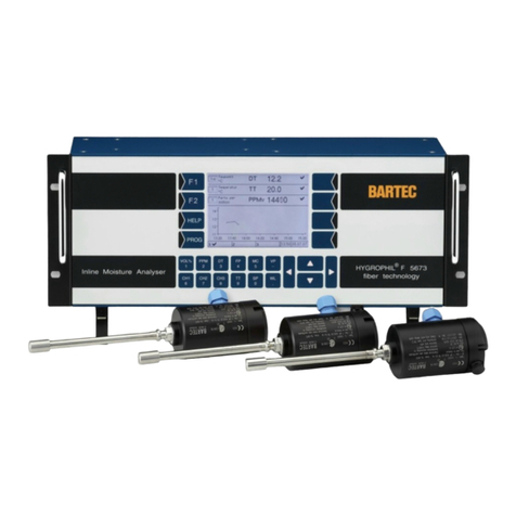
BARTEC BENKE HYGROPHIL F 5673 User manual
BARTEC BENKE
BARTEC BENKE DPA-4.5 User manual
BARTEC BENKE
BARTEC BENKE VISC-4 User manual

BARTEC BENKE
BARTEC BENKE A Series User manual
