Ponsel ACTEON 2000 Series User manual

User manual
PONSEL Référence : NOTICE_ACTEON_2050_v001 V : 002 1/67
WRITTEN BY
R
EVIEWED BY
APPROVED
BY
NAME
:
S
TÉPHANE
LE
GUYADER
NAME
:
P
IERRE
PECCHIA
NAME
:
Y
VAN
BOUDEY
SIGNATURE
:
SIGNATURE
:
SIGNATURE
:
ACTEON 2050
SS-Temperature
User manual

User manual
PONSEL Référence : NOTICE_ACTEON_2050_v001 V : 002 2/67
IMPORTANT
Please read the manual carefully before
switching on the device.
In order to maintain and ensure the good working order of the device, users must comply with
the safety precautions and warnings featured in this manual.
Assembly and activation:
- Assembly, electrical connection, activation, operation and maintenance of the
measuring system must only be carried out by trained personnel duly authorised by the
end-user.
- Trained personnel must be familiar with and comply with the instructions in this
activation manual.
- Make sure the power supply complies with the specifications on the nameplate before
connecting the device.
- A clearly labelled power switch must be positioned near the device.
- Check all connections before turning the power on.
- Do not use damaged equipment: it may represent a hazard and should be labelled as
faulty.
- Repairs must only be carried out by the manufacturer or by a Ponsel after-sales
service.
- Before shutting the ACTEON cover, check that the cover sealing joint is correctly
positioned in its groove.

User manual
PONSEL Référence : NOTICE_ACTEON_2050_v001 V : 002 3/67
CONTENTS
1THE MEASURING SYSTEM................................................................................6
1.1
The basic system ..................................................................................................................................... 6
1.1.1
A Suspended Solids (SS) -Temperature transmitter: ........................................................................... 6
1.1.2
A SS sensor.......................................................................................................................................... 6
1.1.3
Temperature sensor.............................................................................................................................. 6
1.2
Accessories: ............................................................................................................................................. 7
1.2.1
Consumables........................................................................................................................................ 7
1.2.2
Accessories for a tank-mounted installation without cleaning system................................................. 7
1.2.3
Accessories for MES5 (PONCIR-MES5-10) and Temperature sensor in-pipe installation ............... 7
2INSTALLATION ...................................................................................................8
2.1
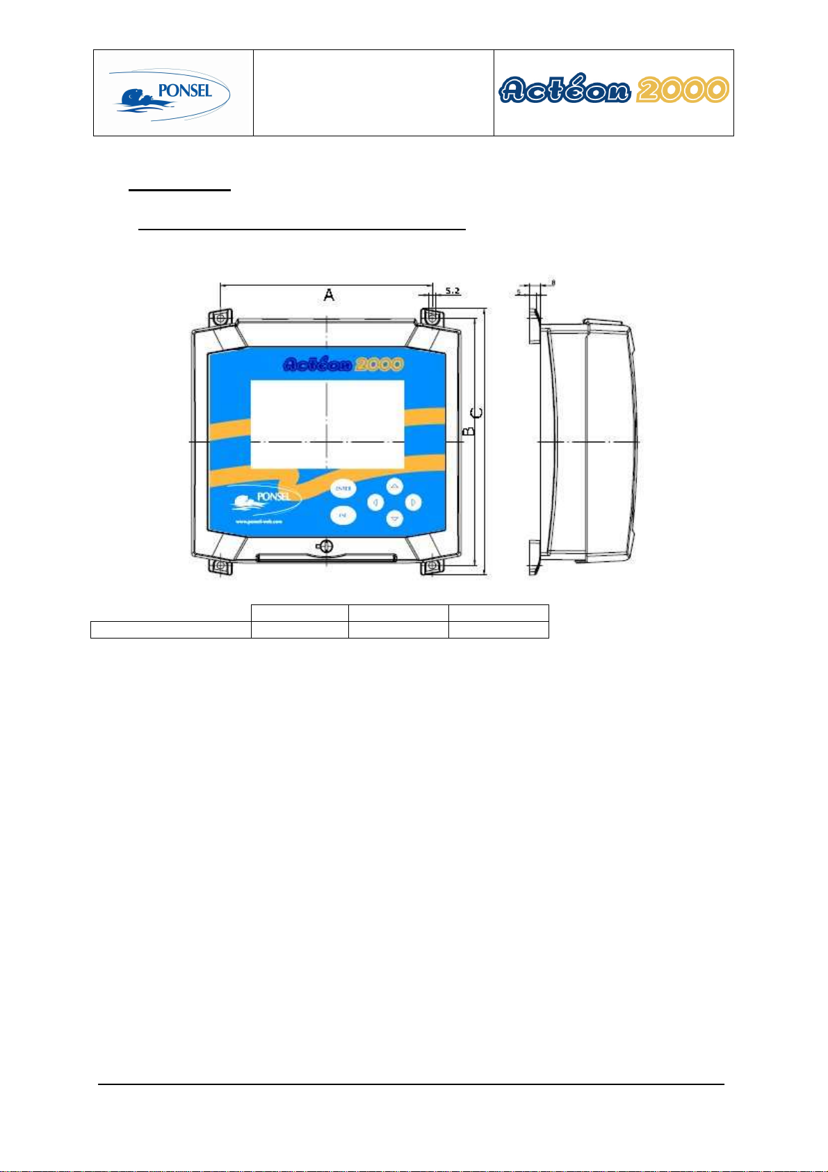
Mounting the ACTEON 2050 transmitter box..................................................................................... 8
2.2
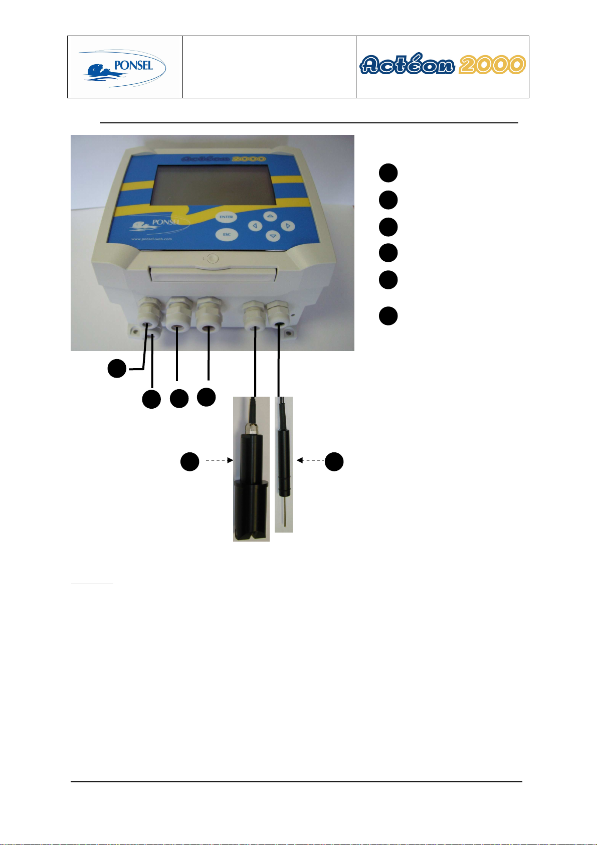
Connecting the ACTEON 2050 transmitter and MES and Temperature sensors............................ 9
2.2.1
Acteon 2050 wiring:........................................................................................................................... 10
2.3
Tank-mounting:.................................................................................................................................... 11
2.3.1
Using the stand and protective hood.................................................................................................. 11
2.3.2
Installing the sensor in the sensor-holder perch (elbowed or straight) (PONPPCC-CIR or
PONPPCD-CIR).............................................................................................................................................. 11
2.3.3
Installing an Elbowed Sensor-Holder Perch (ref: PONPPCC-CIR) or Straight Sensor-Holder Perch
(ref: PONPPCD-CIR) on QRPM (ref: PONSPFR and PONSPFR2)............................................................ 13
2.4
In-pipe installation:............................................................................................................................... 14
3ACTEON 2050 TRANSMITTER.........................................................................15
3.1
Control console:.................................................................................................................................... 15
4BLOCK DIAGRAM OF ACTEON 2050 MENUS:...............................................16
5THE MEASUREMENT WINDOW.......................................................................17
6CALIBRATING THE ACTEON 2050..................................................................18
6.1
Calibrating the sensors:........................................................................................................................ 19
6.1.1
Two point SS sensor calibration (immediate calibration):................................................................. 19
6.1.2
Two point SS sensor calibration (differed calibration):..................................................................... 22
6.1.3
SS sensor slope adjustment:............................................................................................................... 27
6.1.4
Returning to SS measurement theoretical calibration:....................................................................... 29
6.1.5
Two point temperature sensor calibration (complete calibration):..................................................... 30
6.1.6
Adjusting the temperature sensor slope: ............................................................................................ 33
6.1.7
Returning to temperature measurement theoretical calibration:......................................................... 35
6.2
SS sensor calibration error message.................................................................................................... 36
6.2.1
CLEAN WATER calibration error .................................................................................................... 36
6.2.2
SLUDGE calibration error................................................................................................................. 36
6.3
Temperature sensor calibration error message information............................................................ 37
6.3.1
0°C calibration error .......................................................................................................................... 37
6.3.2
Ambient water calibration error......................................................................................................... 37
7VIEWING MEASUREMENT HISTORY..............................................................38

User manual
PONSEL Référence : NOTICE_ACTEON_2050_v001 V : 002 4/67
8VIEWING THE SENSOR CALIBRATION REPORT ..........................................39
9CONFIGURING ACTEON 2050.........................................................................40
9.1
Configuring sensor response averaging.............................................................................................. 41
9.2
Sludge slope coefficient reminder........................................................................................................ 42
9.3
Adjusting SS sensor offset.................................................................................................................... 43
9.4
Configuring the trend line.................................................................................................................... 45
9.5
Configuring the two 4-20mA outputs.................................................................................................. 46
9.5.1
Adjusting 4-20mA output stop thresholds ......................................................................................... 47
9.5.2
Calibrating 4-20mA outputs............................................................................................................... 49
9.6
Adjusting relay outputs........................................................................................................................ 51
9.6.1
Configuring relays in mode 1:............................................................................................................ 52
9.6.2
Configuring relays in mode 2:............................................................................................................ 52
9.6.3
Configuring relays in mode 3:............................................................................................................ 52
9.7
Adjusting measurement units:............................................................................................................. 52
9.8
Setting the language: ............................................................................................................................ 52
9.9
Resetting factory default values: ......................................................................................................... 52
10 INFORMATION MENU.......................................................................................52
11 ADJUSTING THE ACTEON 2050 DISPLAY CONTRAST ................................52
12 TECHNICAL SPECIFICATIONS:.......................................................................52
13 SENSORS..........................................................................................................52
13.1
SS sensor................................................................................................................................................ 52
13.1.1
Specifications:.................................................................................................................................... 52
13.1.2
Mechanical diagram:.......................................................................................................................... 52
13.1.3
Maintenance:...................................................................................................................................... 52
13.2
Temperature sensor.............................................................................................................................. 52
13.2.1
Maintenance:...................................................................................................................................... 52
13.2.2
Mechanical diagram:.......................................................................................................................... 52
14 QUESTIONS & ANSWERS................................................................................52
14.1
Display screen troubleshooting:........................................................................................................... 52
14.2
SS measurement troubleshooting:....................................................................................................... 52
15 APPENDIX:........................................................................................................52

User manual
PONSEL Référence : NOTICE_ACTEON_2050_v001 V : 002 5/67
Figures
Figure 1 - Transmitter mounting diagram............................................................................................................... 8
Figure 2 - Installing a measuring system ................................................................................................................ 9
Figure 3 - Installation with a connection box........................................................................................................ 10
Figure 4 – Transmitter mount and hood................................................................................................................ 11
Figure 5 – Elbowed Sensor-Holder Perch............................................................................................................. 12
Figure 6 - Installing a perch on a QRPM with one or two sliders......................................................................... 13
Figure 7 - SS sensor in-pipe installation ............................................................................................................... 14
Figure 8 – Resetting ACTEON 2050.................................................................................................................... 52
Figure 9 - Transmitter wiring terminal layout....................................................................................................... 52

User manual
PONSEL Référence : NOTICE_ACTEON_2050_v001 V : 002 6/67
1 The measuring system
1.1 The basic system
A measuring system requires the following basic elements:
1.1.1 A Suspended Solids (SS) -Temperature transmitter:
PONACTEON2050-20 ACTEON 2050-20 SS meter and Thermometer
transmitter (0.00-20.00g/l range MES5 sensor)
PONACTEON2050-50 ACTEON 2050-50 SS meter and Thermometer
transmitter (0.00-50.00g/l range MES5 sensor)
1.1.2 A SS sensor
PONCIR-MES5-10 IR optical sensor for suspended solids measurements with
10-metre cable connection and 5mm optical length. Perch
mounting or in-pipe installation. PVC body
1.1.3 Temperature sensor
PONCPC-T-10 Temperature sensor with 10m cable connection (perch-
mounting or in-pipe installation)

User manual
PONSEL Référence : NOTICE_ACTEON_2050_v001 V : 002 7/67
1.2 Accessories:
1.2.1 Consumables
PONMANU-2050
Additional directions for use
1.2.2 Accessories for a tank-mounted installation without cleaning system
PON-ACT-24V Optional 24VDC power supply
PONBJ-E Watertight IP68 connection box for connecting the sensor at
distances over 10 metres
PONCBMC-9 9-conductor coated cable for the Connection box/Acteon 2050
connection
PON-PDPCV-1 PVC stand and protective hood for one ACTEON transmitter
PON-PDPCV-2 PVC stand and protective hood for two ACTEON transmitters
PON-CASQ-1 PVC protective hood for one ACTEON transmitter
PON-CASQ-2 PVC protective hood for two ACTEON transmitters
PONPPCC-CIR PVC elbowed sensor-holder perch for SS, sludge blanket, CTZ,
NTU and TU20 sensors. Supplied with connector
PONPPCD-CIR PVC straight sensor-holder perch for SS, sludge blanket, CTZ,
NTU and TU20 sensors. Supplied with connector. SPECIFIC
APPLICATION
PONCOUDE 90° elbow for sensor-holder perch closure
PONSPFR2C Stainless steel ESHP or SSHP type mount for 2 perches -1 arm,
2 sliders
PONSPFR1C Stainless steel ESHP or SSHP type mount for 1 perch -1 arm, 1
slider
PONSPFR-COUL Additional slider for QRPM (Quick release perch mount)
systems
1.2.3 Accessories for MES5 (
PONCIR-MES5-10
) and Temperature sensor in-pipe
installation
PONVCPO-63 Stainless steel 63mm clamp type assembly for in-pipe
installation (316 L) (for SS OXY, Eh, pH, Temp., C2E and
C4E sensors) To be fitted with the appropriate nipple. To be
welded on stainless steel piping
PONNIP-MES MES5 sensor nipple
PONNIP-T Temperature sensor nipple

User manual
PONSEL Référence : NOTICE_ACTEON_2050_v001 V : 002 8/67
2 Installation
2.1 Mounting the ACTEON 2050 transmitter box
Acteon 2050 mounting diagram
A B C
Dimensions (mm) 156.5 181 195.3
Figure 1 - Transmitter mounting diagram

User manual
PONSEL Référence : NOTICE_ACTEON_2050_v001 V : 002 9/67
2.2 Connecting the ACTEON 2050 transmitter and MES and Temperature sensors
Figure 2 - Installing a measuring system
Comment:
If the connection cable between the sensor and transmitter is longer than 10 metres, a watertight IP 68
connection box must be used (REF: PON-BJ-E).
Relay cable (2 channels)
4-20mA cable (2
channels)
Power supply cable
(230V~ or 24VDC)
Line out cable
1
5
2
3
1
2
3 4
4
SS sensor (PONCIR-
MES5-10)
5
6
Temperature sensor
(PONCPC-T-10)
6

User manual
PONSEL Référence : NOTICE_ACTEON_2050_v001 V : 002 10/67
Figure 3 - Installation with a connection box
2.2.1 Acteon 2050 wiring:
See appendix (§15) at the end of the document.
Relay cable (2 channels)
4-20mA cable (2
channels)
Power supply cable
(230V~ or 24VDC)
Line out cable
1
5
2
3
1
2
3 4
4
SS sensor (PONCIR-
MES5-10)
5
6
Temperature sensor
(PONCPC-T-10)
6
7
7
Connection box
(PON-BJ-E)

User manual
PONSEL Référence : NOTICE_ACTEON_2050_v001 V : 002 11/67
2.3 Tank-mounting:
2.3.1 Using the stand and protective hood
A PVC protective hood (PON-PDPVC-1) is available for mounting the ACTEON 2050.
The hood is essential in the case of direct exposure to adverse weather or sunshine.
Figure 4 – Transmitter mount and hood
2.3.2 Installing the sensor in the sensor-holder perch (elbowed or straight)
(PONPPCC-CIR or PONPPCD-CIR)

User manual
PONSEL Référence : NOTICE_ACTEON_2050_v001 V : 002 12/67
It is best to use the elbowed sensor-holder perch with its own installation system when submerging the sensor in
a tank.
Figure 5 – Elbowed Sensor-Holder Perch
Comment:
Use elbowed sensor-holder perches in heavily soiled tanks to prevent fibre build-up on the perch.
If there is a directional flow, the sensor's optical slit should be pointing in the direction of the flow.
Installing the SS sensor in the nozzle:
The standard sensor comes sealed to a 10-metre cable connection, making it submersible up to a several bars of
pressure.
1) Completely unscrew the tightening seal located on the sleeve of the SS sensor beforehand.
2) Pass the sensor cable through the bottom of the perch (widest end) until it comes out of the other end.
3) Slide the cable through the perch until the SS sensor sleeve fits into the bottom of the perch.
4) Slot the SS sensor sleeve insert in the lateral hole located in the lower end of the perch. Tighten the
lock-nut until the sensor is secured in the perch (do not over tighten).
5) Set the perch on the edge of the tank or on the bridge.
SS sensor
Lock-nut
O-Ring seal
Structure for holding sensor
Elbowed Sensor-Holder Perch
SS sensor
30cm
minimum Liquid flow direction
Liquid level

User manual
PONSEL Référence : NOTICE_ACTEON_2050_v001 V : 002 13/67
2.3.3 Installing an Elbowed Sensor-Holder Perch (ref: PONPPCC-CIR) or Straight
Sensor-Holder Perch (ref: PONPPCD-CIR) on QRPM (ref: PONSPFR and
PONSPFR2)
1) Fix the stainless steel QRPM to the infrastructure.
2) Next, fix a sensor-holder perch to the stainless steel QRPM as shown in the diagram below.
Figure 6 - Installing a perch on a QRPM with one or two sliders
A second slider may be added to install a second sensor-holder perch for the temperature sensor (see diagram
above).

User manual
PONSEL Référence : NOTICE_ACTEON_2050_v001 V : 002 14/67
2.4 In-pipe installation:
The sensors can be supplied for installation in a pressure pipe (<20 bars) with quick release conical
coupling clamps. (see Figure 7 - SS sensor in-pipe installation
)
Figure 7 - SS sensor in-pipe installation
Closed conical
clamps
Connector
attached
View from above
Tightening
screw
2 conical clamps
External weld
Pipe
MES5-Sp sensor for in-pipe installation with a quick
mounting/dismounting system using conical clamps

User manual
PONSEL Référence : NOTICE_ACTEON_2050_v001 V : 002 15/67
3 ACTEON 2050 transmitter
3.1 Control console:
1
1
ENTER key for accessing menus or confirming actions
2
ESC k
ey for exiting menus or cancelling actions
3
key for moving left in menus
4
5
key for moving right in menus
key for increasing a value or selecting the menu above
6
The
key for decreasing a value or selecting the menu below
8
Quarter
-
turn screw to seal the cover
2
5
3
4
6
8
7
7
Control screen

User manual
PONSEL Référence : NOTICE_ACTEON_2050_v001 V : 002 16/67
4 Block diagram of ACTEON 2050 menus:
MEASURE
CONFIGURATION
Language configuration (§9.8)
4-20mA output
adjustment
Relay output
CALIBRATION
Sensor offset adjustment (§9.3)
Measure unit configuration (§9.7)
GENERAL
INFORMATION
HISTORY
CALIBRATION
LOGGER
Config. of 4mA and 20mA
stop switches (§
9.5.1
)
4-20mA output calibration
(§9.5.2)
Threshold adjustment in
mode 1 (§
9.6.1
)
Threshold adjustment in
mode 2 (§
9.6.2
)
Factory default configuration reminder (§
9.9
)
Gain adjust (§6.1.3)
Differed calibration (§6.1.2)
Theoretical calibration (§6.1.4)
Gain adjust (§6.1.6)
Complete calibration (§
6.1.5
)
Theoretical calibration (§
6.1.7
)
SS sensor
Temperature sensor
Immediate calibration (§6.1.1)
Averaging sensor response (§9.1)
Sludge slope coefficient reminder (§0)
Graphic screen adjustment (§9.4)
Threshold adjustment in
mode 3 (§
9.6.3
)

User manual
PONSEL Référence : NOTICE_ACTEON_2050_v001 V : 002 17/67
5 The measurement window
In measure mode the measurement screen displays various information:Erreur !
20.00
°C
-
24
hrs
2.31
MEASURE
g/l
INFO
CONF
HIST
CAL
LOG
MEAS
R1
R2
!
CAL
ACT
EON 2050
-
20 Turbidimeter
g/l
1
3
1
2
3
4
5
1
SS measurement
2
Measurement state indicator:
THEOR CAL
: Indicates use of the theoretical coefficients as calibration
coefficients.
: Indicates incorrect calibration point on the probe.
6
Temperature transmitted by the temperature sensor
In the event of faulty wiring or uninstalled sensor, the temperature will not be displayed.
Comment: The following icon is displayed if the temperature is higher than the operating
temperature (55°C)
3
: No icon displayed means that the last calibration is correct.
Mode1
4
R1 and R2 relays: state and operating
mode
ACTEON menu
5
6
Trend line can be configured from 1
min to 24
hours (with automatic s
caling)
Contact is inactive.
Contact is active.
HOT
!
DRY
WEIGHT
: Indicates differed calibration has been carried out but the dry weight has
not yet been entered.
!
CAL
!
!

User manual
PONSEL Référence : NOTICE_ACTEON_2050_v001 V : 002 18/67
6 Calibrating the ACTEON 2050
Important information.
Calibration frequency:
The SS sensor must be calibrated (zero + slope) at least once every two weeks, during the regular optics cleaning
process.
However, recalibration is advisable as soon as a shift of more that +/-0.2g/l occurs (during automatic control
with a recently calibrated reference SS meter, or during "dry weight" analysis, while taking account of the fact
that the analysis can sometimes be delayed by up to 24 hours in relation to the current state of the active sludge
measured with the controlled PONSEL SS-meter. Hence the possible use of a "differed calibration" to
compensate for this problem).
If frequent recalibrations are carried out (once a day for example), there is no need to take the sensor + perch out
of the water, clean the optics or zero adjust in clean water. Simply adjust the slope in situ by leaving the sensor
in place in the sludge being measured.
Sensor calibration and positioning procedures: Even though, in our detailed explanations, we have always
mentioned sludge specimens taken from tanks and placed in buckets for sensor calibration, there is no objection
to calibrating the sensor in situ attached to a perch and placed in the measurement medium at the point where it
will subsequently be installed for regular measurements. The sludge content in g/l may already have been
measured for this point ("immediate calibration" or "gain adjust" menus), for instance by using a recently
calibrated reference SS meter, or sludge may be taken from near the optical measurement unit and analysed
while immediately following up with a "differed calibration" without waiting on the results of this analysis.
In this case calibrate in situ during a stable stage in the activation process. Avoid calibrating during bubble
aeration or during stagnation periods. Calibration should preferably take place after aeration. An SS sensor
should be placed in the most stable hydraulic conditions possible, without excessive turbulence or stagnation,
and with regular mixing, so that the SS are perfectly suspended in the medium and that the location is
representative of the SS content in the tank as a whole and in the active sludge area.
In situ calibration remains relevant in the sense that it integrates the hydraulic mixing regime and suspends the
SS, while sludge in a pail only approximates this hydraulic mixing regime, and can thus result in more or less
large measurement differentials in the tank after calibration. Moreover, in situ calibration is carried out at the
tank's temperature thus preventing heat shocks and shifts.

User manual
PONSEL Référence : NOTICE_ACTEON_2050_v001 V : 002 19/67
6.1 Calibrating the sensors:
Select the calibration menu in the measurement window:
6.1.1 Two point SS sensor calibration (immediate calibration):
Use the following procedure to calibrate your SS sensor in one go; zero and slope adjustments (gain adjust) are
carried out immediately afterwards. This procedure requires previous knowledge of the SS content of the
activated sludge sample used as the calibration solution. This information can be had either via a recently
calibrated reference SS meter or through analysis of a fraction of the sample sludge immediately after sample
taking then refrigerating the remaining amount at 4°C in an airtight bottle in the dark to prevent fermentation.
Once the analysis results have been obtained, the sludge can be used as calibration solution during this
"immediate calibration" procedure, provided that it is brought up to tank temperature.
Clean the SS sensor beforehand. The sensor optics must be free of dirt and stains (clean optical slit with damp
cloth). See MAINTENANCE chapter (§
13.1.3
) for cleaning instructions.
20.00
°C
-
24
hrs
2.31
MEASURE
g/l
INFO
CONF
HIST
CAL
LOG
MEAS
Mode1 R1
R2
ACTEON 2050
-
20
Turbidimeter
g/l
1
3
Use the
and
keys to
navigate the ACTEON menu
CALIBRATION
SENSORS CALIBRATION
SS SENSOR
Gain adjust
Immediate calibration
Differed calibration
Theoretical calibration
TEMPERATURE SENSOR
Zero rectification
Complete calibration
Theoretical calibration
ENTER: Validate the choice
Select the menu then press ENTER.
CAL

User manual
PONSEL Référence : NOTICE_ACTEON_2050_v001 V : 002 20/67
CALIBRATION
SENSORS CALIBRATION
SS SENSOR
Gain adjust
Immediate calibration
Differed calibration
Theoretical calibration
TEMPERATURE SENSOR
Gain adjust
Complete calibration
ENTER: Validate the choice
Use the
and
keys to select
the type of calibration and the
probe to be calibrated.
Select the
Immediate calibration
menu and
press ENTER
.
Use the
and
keys to move the
cursor in the name section.
Use the keys
and
to change the
letters. (The scrolling order of the
letters is A…Z,0..9,?,>,space)
Enter your name or reference then press ENTER
CALIBRATION
OF SS SENSOR
ESC: Cancel the procedure
ENTER: Start calibration
Enter your name:
Durant
Dip the sensor in clean water with no bubbles (tap water
for example). Preferably, this water must be at the same
temperature as the tank sludge in which the probe will be
placed.
Stir the water with the probe to disperse any bubbles on
the optic windows.
Other manuals for ACTEON 2000 Series
1
This manual suits for next models
1
Table of contents
Other Ponsel Measuring Instrument manuals
Popular Measuring Instrument manuals by other brands

AndroTec
AndroTec Metor MTR-125 Operator's manual

Anritsu
Anritsu MX269017A Operation manual

Funk Amateur
Funk Amateur FA-VA4 Construction and user manual

mru
mru VARIOluxx user manual

Awareness Technology
Awareness Technology ChemWell-T 4600 Series Service manual

SKY PARAGLIDERS
SKY PARAGLIDERS SKYLIGHTER 3 user manual