Bartell Global CONTEC CT250 User manual

Doc. # OIPB-C15009
Orig. Rel. –08/2020
Curr. Rev. - 00
FLOOR PLANER/SCARIFIER
CT250
OWNER’S MANUAL AND PARTS BOOK

CT250 FLOOR PLANER/SCARIFIER
OWNER’S MANUAL AND PARTS BOOK
2
OIPB –C15009
Index
1. Machine applications ...3
2. Technical data ...3
2.1 Planer ...3
2.2 Tools ...3
3. Applications of the tools ...4
4. Safety rules ...4
5. Operating ...4
6. Changing the drum ...5
7. Adjusting the drum ...5
8. Maintenance and cleaning ...6
8.1 Bearings ...6
8.2 Height adjustment and joints ...6
8.3 Belt drive ...6
8.4 Cleaning ...6
9. Diagram ...7
10. Appendix ...7
CT250 FLOOR PLANER/SCARIFIER
OWNER’S MANUAL AND PARTS BOOK
3
OIPB –C15009
1. Machine applications
Planing of horizontal, dry floors such as concrete and steel surfaces with or without a coating and
asphalt using CONTEC®planing tools. The use of the machine outside is only possible in dry weather.
2 Technical data
2.1 Planer
Width of cut
250 mm (10 in)
Width
44 cm (17 in)
Length
104 cm (41 in)
Height
99 cm (39 in)
Weight
135 kg (298 Ibs)
Dust port ¢
70 mm (2.86 in)
Height adjustment
Hand wheel and lever
Electric motor
USA
460 V, 9 kW (12 hp), 60 Hz
Honda petrol
9 hp
Other motors
On request
Average value of acceleration ahv *
8.6 m/s2
Noise level Lwa *
109 dB(A)
Noise level Leq *
96 dB(A)
2.2 Tools
Drum diameter
180 mm (7.3 in)
Cutter shaft diameter
16 mm (0.65 in)
Number of shafts
6
TCT Cutter
57/6
Milling cutter
57/20
Beam flails
57
Cutter diameter
57
Max. No. of cutters
132
Max. No. of milling cutters
36
All specifications are approximate and subject to confirmation. They should only be used as a guide.

CT250 FLOOR PLANER/SCARIFIER
OWNER’S MANUAL AND PARTS BOOK
4
OIPB –C15009
3. Applications of the tools
TCT
Cutters
Heavy duty, long life cutters for all concrete texturing, scabbling, planing
and grooving applications. Also used for removal of road markings, roof
chippings and brittle coatings
Milling
cutters
Primarily for the removal of thermoplastic road / runway markings.
Tipped with tungsten carbide they are cost effective and highly efficient.
A range of cutter dimensions are available.
Beam flails
Heat treated cutters for the removal of paint coatings and laitance from
new concrete. Also for removing grease, dirt and ice deposits.
4. Safety rules
Attention ! The CT 250 floor planers are constructed according to existing safety rules and
regulations. These technical precautions should not be removed or changed under any circumstances.
While operating the machines the following points should also be kept in mind:
1. The planers should always be operated with all safety covers and technical precautions.
2. The operator should never leave the machine during operation.
3. Before leaving the machine all rotary parts should be brought to a stand still. The electric models
must be disconnected from the mains. Make sure that the machine cannot roll or move by itself.
4. After maintenance and adjustment all safety covers must be reattached.
5. If the noise level exceeds 90 dB(A) ear protectors must be worn.
6. In the event of a large amount of dust during operation connect a dust collector to the planer.
5. Operating
After mounting the appropriate tools the operation of the planer can begin.
The lever of the height adjustment (Appendix diagram No. 97 and 99) has to be in the upper position
before the machine is switched on. The hand wheel of the height adjustment must also be turned anti-
clockwise as far as possible.
Switch the motor on. Make sure the motor is spinning in the correct direction. If not, two phases of
the power supply have to be swapped with each other. The correct direction is indicated by an arrow
on the motor fan.
Attention: Operating the machine with the motor spinning in the wrong direction can cause serious
injury to the operator. The machine will jump towards the operator.
Lower the planer with the lever to the operating position. Turn the hand wheel of the height
adjustment until the tools are lowered to the floor and until you achieve the required finish.
Attention: Lowering the tools too much decreases the performance of the machine. You will also

CT250 FLOOR PLANER/SCARIFIER
OWNER’S MANUAL AND PARTS BOOK
5
OIPB –C15009
destroy the shafts in the drum and the bearings of the machine.
Attention: Never switch the motor of the planer on while the tools still touch the floor. Always lift
the machine and the tools clear from the floor and then switch the motor on.
Heavy dust can be avoided by connecting a dust collector to the dust port.
The vibration damped handle bar ensures an easier operation.
6. Changing the drum
Attention: Before any maintenance, the machine must be brought to a complete stand still. Always
disconnect the machine if it is an electric model.
-Lift the machine with the lever so that the tools are well clear of the floor.
-Unscrew the screws on the right side plate (M10, Key width 17 mm)
-Carefully remove the side plate.
-Take out the drum. Remove worn out tools. Check shafts and drums for wear and tear. If
necessary replace new tools on the drum.
-Push drum on freshly greased shaft.
-Reconnect side plate.
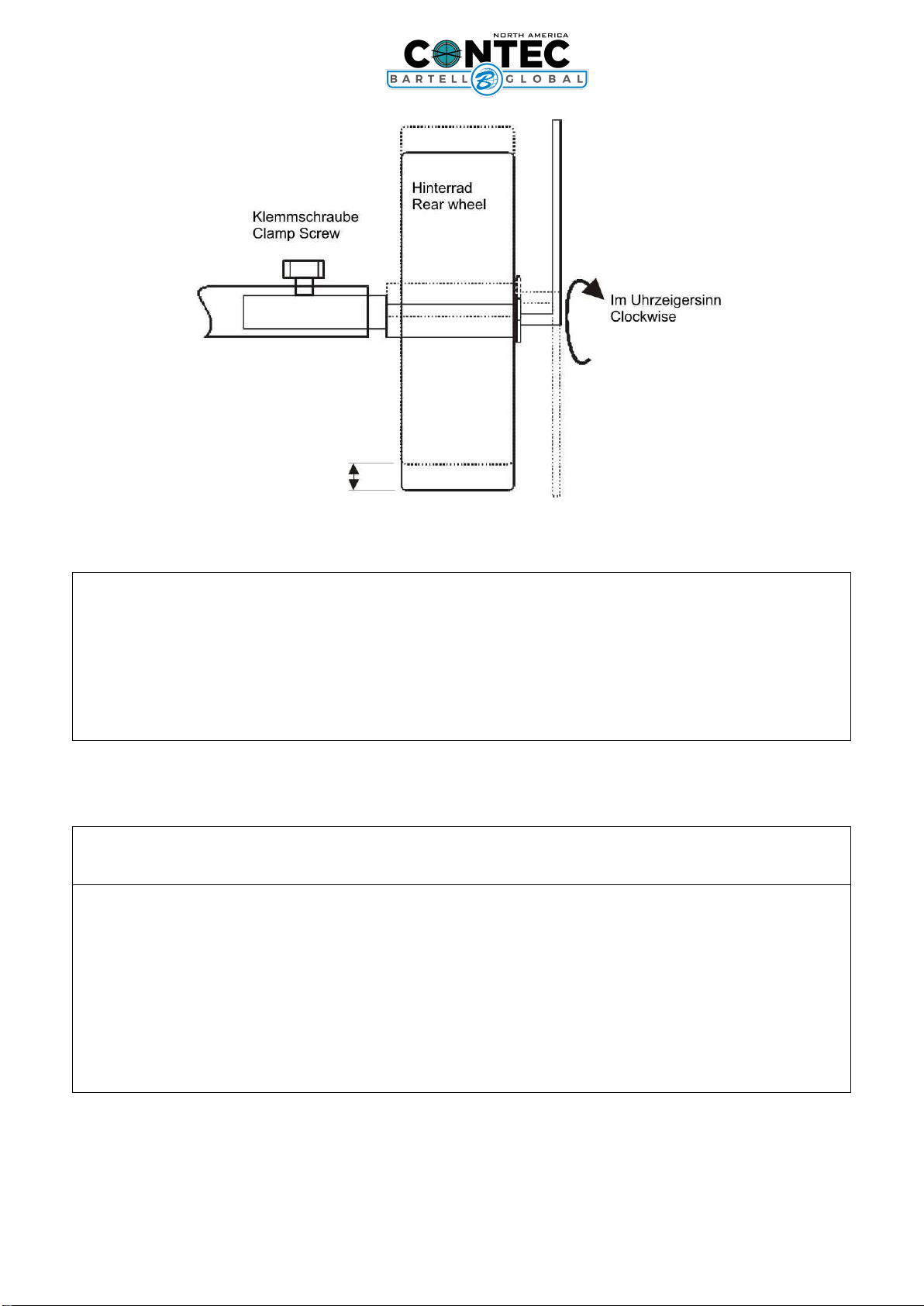
7. Adjusting the drum
During the operation of the CT 250 floor planer or after a drum has been changed or replaced, the
drum shaft and the rear wheel axis can fall out of alignment. This results in an uneven track on the
floor. On one side the drum touches the floor before the other and therefore removes more surface
material on this side.
The two rear wheels are mounted on an eccentric shaft (see diagram).
CT250 FLOOR PLANER/SCARIFIER
OWNER’S MANUAL AND PARTS BOOK
6
OIPB –C15009
If the drum has to be adjusted proceed as follows: Place the planer on an even floor. Lift the machine
with the height adjustment hand wheel, until all the tools are well clear of the floor. Loosen the
clamping screw of the eccentric shaft. On the other side of the rear wheel is a screw which keeps the
wheel on the shaft. Turning the screw will also turn the eccentric shaft. The floor planer moves up
and down on one side. Always turn the screw clockwise. Anti clockwise would loosens the screw.
Keep turning until all the tools on the drum are the same distance to the floor. Tighten the clamping
screw again.
8. Maintenance and cleaning
8.1 Bearings
All bearings are greased for their life time.
8.2 Height adjustment and joints
All joints have to be greased periodically with a standard machine grease.
8.3 Belt drive
Check the belt after approximately every 30 hours of operation. For tensioning the belt you need to
change the position of the belt tensioner wheel underneath the belt cover.
8.4 Cleaning
Regular cleaning of the machine increases the life of all components and tools of the planer.
CT250 FLOOR PLANER/SCARIFIER
OWNER’S MANUAL AND PARTS BOOK
7
OIPB –C15009
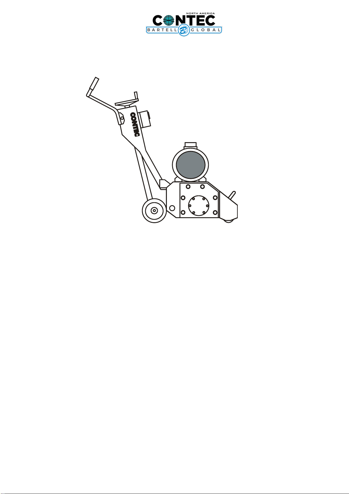
9. Diagram
Handle bar
Height adjustment hand wheel
On- Off switch for electric models
Motor
Rear wheel
Front wheel
Left side plate
10. Appendix
Diagrams
Wire diagram
Tools
Part list
CT250 FLOOR PLANER/SCARIFIER
OWNER’S MANUAL AND PARTS BOOK
8
OIPB –C15009
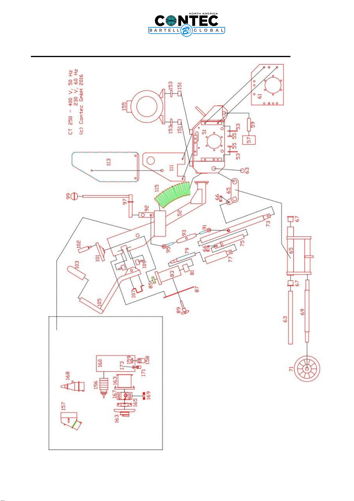
PARTS LIST 1 –CT250 MAIN ASSEMBLY Electric Version

CT250 FLOOR PLANER/SCARIFIER
OWNER’S MANUAL AND PARTS BOOK
9
OIPB –C15009
PARTS LIST 2 –CT250 MAIN ASSEMBLY Gas Version

CT250 FLOOR PLANER/SCARIFIER
OWNER’S MANUAL AND PARTS BOOK
10
OIPB –C15009
PARTS LIST 3 - CT250 BELT DRIVE AND SHAFT

CT250 FLOOR PLANER/SCARIFIER
OWNER’S MANUAL AND PARTS BOOK
11
OIPB –C15009
PARTS LIST 4 –CT250 DRUM ASSEMBLY
CT250 FLOOR PLANER/SCARIFIER
OWNER’S MANUAL AND PARTS BOOK
12
OIPB –C15009
PARTS LIST 5 –CT250 DRUM ASSEMBLY 2

CT250 FLOOR PLANER/SCARIFIER
OWNER’S MANUAL AND PARTS BOOK
13
OIPB –C15009
PARTS LIST 6 –CT250 ELECTRIC DIAGRAM

CT250 FLOOR PLANER/SCARIFIER
OWNER’S MANUAL AND PARTS BOOK
14
OIPB –C15009
PARTS LIST –CT250 MAIN ASSEMBLY
Item #
Part #
Description
QTY
3
19-10-07-03
Bearing Lid right Side
1
5
61-30-00-47
Circlip
1
7
61-20-62-10
Bearing right Side
1
9
19-21-07-06
Hexagon Ring
1
11
19-10-07-04
Bearing Housing right Side
1
13
19-21-07-05
Drive Shaft
1
17
68-85-30-8-7
Key
1
19
19-10-07-01
Spacer
1
21
61-30-01-70
Circlip
1
23
61-20-32-07
Bearing left Side
1
25
19-10-07-02
Bearing Housing left Side
1
27
19-21-07-07
Nut on Drive Shaft
1
29
70-44-8M-50
Pulley Drum
1
30
19-10-70-15
Lock for Pulley
1
31
70-24-08-80
Belt
1
33
70-24-8M-50
Motor Pulley
1
35
70-26-27-00
Belt Tensioner
1
37
19-10-12-04
Bracket for Tensioner
1
39
19-10-12-03
Bracket for Tensioner
1
51
19-10-01-00
Chassis
1
53
70-24-16-60
Rubber Sealing front/rear
2
55
19-10-13-01
Bracket for Rupper Sealing
2
57
80-20-80-60
Front Wheel
1
59
19-10-01-07
Front Wheel Axis
1
61
19-10-01-01
Side Plate
1
63
19-10-04-05
Axle for Wingarm
1
65
19-10-04-00
Wing Arm for rear Axis
1
66
60-33-12-25
Pin for lifting Rod
2
67
61-24-50-30
Bronze Bearing
1
69
19-10-04-06
Rear Axis with Excenter
1
71
80-20-31-60
Wheel
2
73
19-10-05-05
Lifting Rod lower Part
1
75
19-10-05-06
Lifting Rod upper Part
1
77
19-10-05-03
Height Control Piston
1
79
19-10-05-02-C
Spindle
1
81
61-24-40-46
Bronze Bearing
1
83
19-10-05-01
Housing Height Adjustment
1
85
61-20-63-02
Lager Bearing
1
87
19-10-02-07
Cover
1
89
60-30-10-50
Cross Handle Screw
1
91
61-50-12-60
Eye Screw
2

CT250 FLOOR PLANER/SCARIFIER
OWNER’S MANUAL AND PARTS BOOK
15
OIPB –C15009
92
19-10-10-01
Lever
1
93
19-10-05-07
Spanner Nut
2
95
61-50-12-60-L
Eye Screw left Threat
1
97
19-10-05-08
Lever
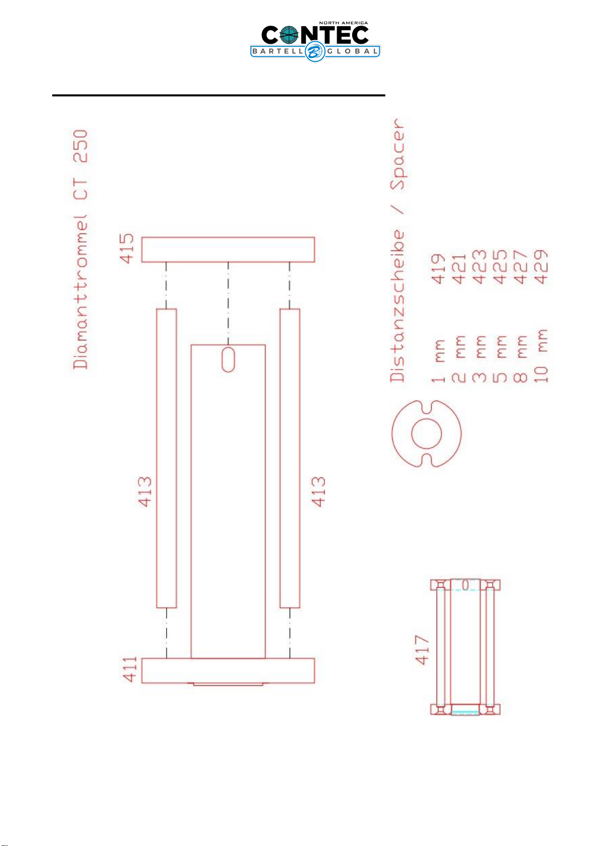
1
99
90-21-45-12
Ball Head
1
101
90-21-95-50
Level Adjustment Wheel
1
102
90-21-95-51
Knob for Handwheel
1
103
70-21-26-10
Rubber Grip
1
105
19-10-03-01
Handle
1
107
70-26-18-00
Bracket for Rubber Block
2
109
70-26-30-00
Rubber Block
4
111
19-10-06-01
Bracket for Belt Cover
1
113
19-10-06-03
Belt Cover
1
115
70-25-02-70
Dusthose
1
151
19-10-12-08
Motor Spacer
4
153
19-10-12-05
Bracket for Electric Motor
2
155
55-03-46-75
Motor
1
156
50-20-20-04
Star-Delta-Switch
1
157
50-20-16-01
Wall Plug
1
158
50-20-23-M-25
Cable Gland
1
159
50-20-23-GM-M-25
Nut
1
160
50-10-10-41
Switch Box
1
163
51-10-10-01
Motor Protective Switch Box
1
165
51-20-30-03
Low Voltage Protective
1
167
51-20-30-01
Motor Protective
1
169
50-20-10-07
Auxiliary Switch
1
171
50-20-23-M-16
Cable Gland
1
173
50-20-23-GM-M-16
Nut
1
300
95-10-250-T
Drum
1
301
95-16-57-06
TC Cutters 57/6
1
303
95-16-57-20
Milling Flails 57 / 20
1
307
95-16-30-17
Spacer
1
309
95-10-250-A
Axis for Drum
6
311
95-10-250-S
Drum Side Disc
2
411
19-10-55-24
Drum Shaft with Flange
1
413
19-10-55-13
Shaft for Diamond Drum
2
415
19-10-55-03
Flange for Diamond Drum
1
417
19-10-55-11
Drum for Diamond Blades
1
419
19-10-55-17
Spacer 1mm for Diamond Drum
1
421
19-10-55-14
Spacer 2mm for Diamond Drum
1
423
19-10-55-15
Spacer 3mm for Diamond Drum
1
425
19-10-55-16
Spacer 5mm for Diamond Drum
1
427
19-10-55-18
Spacer 8mm for Diamond Drum
1
429
19-10-55-19
Spacer 10mm for Diamond Drum
1

Doc. # OIPB-C15009
Orig. Rel. –08/2020
Curr. Rev. - 00
Table of contents
Other Bartell Global Floor Machine manuals


