Bartell Global Innovatech Terminator T-2200PRO User manual
For machines with serial no. format: T2200P-mmyy-XXX OIPB-I03026-T2200PRO_v3.1
I
RIDE-ON TERMINATORS
T-2200PRO
COMPLETE MANUAL
Discount-Equipment.com

Discount-Equipment.com is your online resource for commercial and industrial
quality parts and equipment sales.
Locations:
Florida (West Palm Beach): 561-964-4949
Outside Florida TOLL FREE: 877-690-3101
Need parts? Check out our website at www.discount-equipment.com
Can’t find what you need?
Click on this link: http://www.discount-equipment.com/category/5443-parts/ and fill out
the request form.
Please have the machine model and serial number available in order to help us get
you the correct parts. One of our experienced staff members will get back to you with
a quote for the right part that your machine needs.
We sell worldwide for the brands: Genie, Terex, JLG, MultiQuip, Mayco, Toro/Stone,
Diamond Products, Magnum, Airman, Mustang, Power Blanket, Nifty Lift, Atlas Copco,
Chicago Pneumatic, Allmand Brothers, Essick, Miller Spreader, Skyjack, Lull, Skytrak,
Tsurumi, Husquvarna/Target, Whiteman-Concrete/Mortar, Stow-Concrete/Mortar, Baldor,
Wacker, Sakai, Snorkel, Upright, Mi-T-M, Sullair, Neal, Basic, Dynapac, MBW, Weber,
Bartell, Bennar Newman, Haulotte, Ditch Runner, Blaw-Knox, Himoinsa, Best, Buddy,
Crown, Edco, Wyco, Bomag, Laymor, Terremite, Barreto, EZ Trench, Takeuchi, Basic, Bil-
Jax, Curtis, Gehl, Heli, Honda, ICS/PowerGrit, Puckett, Waldon, ASV, IHI, Partner, Imer,
Clipper, MMD, Koshin, Rice, Gorman Rupp, CH&E, Cat Pumps, Comet, General Pump,
Giant,AMida, Coleman, NAC, Gradall, Square Shooter, Kent, Stanley, Tamco, Toku, Hatz,
Kohler, Robin, Wisconsin, Northrock, Oztec, Toker TK, Rol-Air, Small Line, Wanco, Yanmar
Discount-Equipment.com

P a g e | 2
OIPB-I03026-T2200PRO_v3.1
REV.
DATE
DESCRIPTION
APPROVED BY:
1.0
04/17/14
1.1
05/18/15
2.0
06/16/15
2.1
07/01/15
3.0
11/14/17
Reformatted and revised text
3.1
03/26/18
Updated and added exploded views
Discount-Equipment.com
P a g e | 3
OIPB-I03026-T2200PRO_v3.1
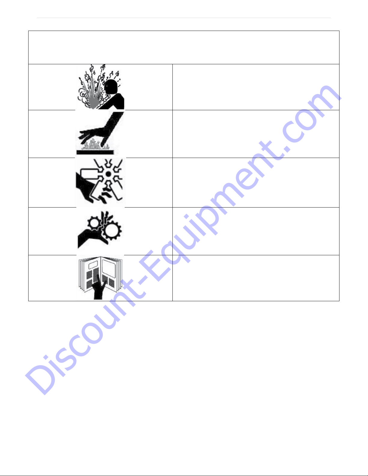
SAFETY PRECAUTIONS
DANGER
EXPLOSION HAZARD
Never operate the machine in an explosive
atmosphere, near combustible materials, or
where ventilation does not clear exhaust fumes.
WARNING
BURN HAZARD
Never come into contact with the engine or
muffler when engine is operating or shortly after it
is turned off. Serious burns may occur.
WARNING
ROTATING HAZARD
Never place hands or feet inside safety guard
rings. Serious injury will result from contact with
rotating blades.
CAUTION
MOVING PARTS
Before starting the machine, ensure that all
guards and safety devices are in place and
functioning properly.
ATTENTION
READ OWNER’S MANUAL
Read and understand owner’s manual before
using this machine. Failure to follow operating
instructions could result in serious injury or death.
Discount-Equipment.com

P a g e | 4
OIPB-I03026-T2200PRO_v3.1
TABLE OF CONTENTS
1. INTRODUCTION 6
2. ABOUT THIS MANUAL 6
3. IMPORTANT SAFETY INSTRUCTIONS 7
o
1.
SAFETY INSTRUCTIONS FOR ALL TOOLS 7
o
2.
ADDITIONAL SAFETY RULES FOR RIDING FLOOR SCRAPERS 8
4. GENERAL OPERATING INSTRUCTIONS FOR THE TERMINATOR®9
5. SAFETY FEATURES 9
o1. AUTO STOP 9
o2. WARNING LIGHT AND BACK-UP ALARM 9
o3. FIRE EXTINGUISHER 9
o4. EMERGENCY BATTERY DISCONNECT 9
o5. SAFETY INSTRUCTIONS 10
6. T2200 PRO TERMINATOR®SPECIFICATIONS 10
o1. TOOLS AND SUPPLIES 10
7. VENTILATION REQUIREMENTS 11
8. GUARDS, WARNING NOTICES & SIGNS 11
9. SERVICE INSTRUCTIONS & PERSONNEL 11
10. REPLACEMENT PARTS & MATERIALS 11
11. UNCRATING AND PREPARING THE TERMINATOR®FOR OPERATION 12
o1. TO REMOVE THE TERMINATOR®FROM A CRATE WITH A FORKLIFT:12
o2. TO REMOVE THE TERMINATOR®FROM A CRATE WITHOUT A FORKLIFT:12
12. LOADING/UNLOADING PROCEDURES 12
13. OPERATOR CONTROLS 13
o1. DRIVE/JAW CONTROLS 13
o2. AUTO STOP 13
o3. OPERATOR PRESENCE SWITCH &SAFETY GRIPS 13
o4. EMERGENCY BRAKE 13
14. DISPLAY & INDICATORS 13
o1. TACHOMETER &INFORMATION DISPLAY 13
o2. MALFUNCTION INDICATOR LIGHT 14
o3. HYDRAULIC FILTER CLOG INDICATOR 14
15. ACCEPTABLE CARBON MONOXIDE LEVELS 14
16. BLADE ASSEMBLY 14
17. TAKING UP FLOOR COVERINGS 14
Discount-Equipment.com

P a g e | 5
OIPB-I03026-T2200PRO_v3.1
18. BALLAST 15
19. TRICYCLE OR CASTER WHEELBASE AND TIRES 15
20. CARBON MONOXIDE INFORMATION 15
o1. WHAT IS CARBON MONOXIDE 15
o2. ARE YOU LIKELY TO BE POISONED?15
o3. WHAT ARE THE SYMPTOMS?16
o4. WHAT CAN YOU DO ABOUT CO? 16
o5. EMPLOYERS 16
o6. WORKERS 16
o7. FEDERAL STANDARDS 17
21. PROPANE SAFETY 17
o1. PRECAUTIONS &WARNINGS 17
o2. WHAT TO DO IF YOU SMELL GAS 17
22. MAINTENANCE PROCEDURES 17
23. PARTS LIST 19
24. WARRANTY 48
Discount-Equipment.com

P a g e | 6
OIPB-I03026-T2200PRO_v3.1
1. Introduction
The Terminator®Carpet and Tile Removal Machine is intended for use on large demolition
and asbestos abatement projects as well as smaller floor covering removal jobs. Designed
and built by experienced floor covering demolition and installation experts, the machine
incorporates several design features that are essential for efficient operation:
•Tricycle wheelbase and short turning radius allows for better turning ability - especially
in narrow spaces.
•Jaw position and tool position adjustments allow for changing the angle of the blade for
any application.
•Ballasts in the front and rear provides extra traction needed for tile and glue removal.
•Built-in forklift transportation slots allow for easy loading and unloading at job sites.
•Variable displacement hydraulic control for a smooth start and stop.
If operated and cared for as instructed in this Manual, the Terminator®provides trouble-
free, safe, and efficient performance.
2. About This Manual
This Manual contains the information and procedures to assist you to operate and
maintain the Terminator®machine safely and correctly. Read this Manual before you
operate or service the equipment.
NOTE: Throughout this Manual, directional instructions (left, right, up, down, push, pull,
etc.) are given from the point of view of the operator performing the action.
Discount-Equipment.com

P a g e | 7
OIPB-I03026-T2200PRO_v3.1
3. Important Safety Instructions
WARNING: When using electric tools, basic safety precautions should always be
followed to reduce the risk of fire, electric shock, and personal injury, including the
following: READ ALL INSTRUCTIONS
1.
Safety Instructions for All Tools
• KEEP GUARDS IN PLACE and in working order.
• REMOVE ADJUSTING TOOLS AND WRENCHES. Form habit of checking to see that
keys and adjusting wrenches are removed from the Terminator®before turning tool on.
• KEEP WORK AREA CLEAN. Cluttered areas invite accidents.
• KEEP CHILDREN AWAY. All visitors should be kept a safe distance from the work area.
• WEAR PROPPER APPAREL. No loose clothing, gloves, neckties, rings, bracelets or
other jewelry to get caught in moving parts. Non-slip footwear is recommended. Wear
protective hair covering to contain long hair.
• ALWAYS WEAR SAFETY GLASSES. Also use a face or dust mask if operating in a
dusty environment. All users and bystanders must wear eye protection that conforms to
ANSI Z87.1. (CAN/CSA Z94.3)
• MAINTAIN EQUIPMENT WITH CARE. Keep equipment clean for best and safest
performance. Follow instructions for lubrication and changing accessories.
• DISCONNECT BATTERY before servicing.
• REDUCE THE RISK OF UNINTENTIONAL STARTING. Make sure handles are centered
and the engine throttle control is at the lowest setting.
• USE RECOMMENDED ACCESSORIES. Consult the instruction manual for
recommended accessories.
• NEVER STAND ON TOOL. Serious injury could occur if the machine is tipped or rocked.
• CHECK DAMAGED PARTS. Before further use of the tool, a guard or other part that is
damaged should be carefully checked to determine that it will operate properly and perform
its intended function. Check for alignment of moving parts, binding of moving parts,
breakage of parts, mounting and any other conditions that may affect its operation. A guard
or other part that is damaged should be properly repaired or replaced. Do not use tool if
switch does not turn it on and off.
• NEVER LEAVE EQUIPMENT RUNNING UNATTENDED. TURN POWER OFF. Don’t
leave equipment until it comes to a complete stop.
• DO NOT OPERATE ELECTRIC TOOLS NEAR FLAMABLE LIQUIDS OR GASSES OR
EXPLOSIVE ATMOSPHERES. Motors in these tools may spark and ignite fumes.
• ALWAYS PROVIDE PROPER VENTILATION. Ventilation is required when using the
Terminator® T2200 PRO. Positive or negative pressure ventilators must be used in any
enclosed space where the machine is to be used. Use carbon monoxide (CO) monitoring
when the machine is in-use indoors. The CO generated by propane engines can be
hazardous to your health if not proper ventilation is not provided.
Discount-Equipment.com

P a g e | 8
OIPB-I03026-T2200PRO_v3.1
2.
Additional Safety Rules for Riding Floor Scrapers
CAUTION: FAILURE TO HEED THESE WARNINGS MAY RESULT IN SERIOUS
PERSONAL INJURY OR DEATH AND SERIOUS DAMAGE TO THE
TERMINATOR®.
The Terminator®is to be operated only by qualified, trained personnel.
DON’T attempt to operate the Terminator®if you are not thoroughly familiar with the
operation of the Terminator®.
DON’T operate the Terminator®unless every guard, warning notice or sign is in place.
DON’T use the Terminator®on roofs or floors not designed to carry the weight of the
machine.
DON’T attempt to operate on anything but the designated voltage.
DON’T wedge anything against the motor fan to hold motor shaft.
DON’T operate equipment without guards in place.
DON’T operate the Terminator®near an open flame or smoking materials.
DON’T stand directly behind or in front of the Terminator®when power is enabled.
DON’T lift the hood, inspect the blade, or otherwise service or maintain the Terminator®
while power is enabled.
DON’T operate the Terminator®if the top cover is open.
DON’T overreach. Keep proper footing and balance at all times.
DON’T run the machine into piles of debris, as this may cause the machine to become
unstable and tip over.
DON’T sit on or stand next to, under or around the Terminator®when it is being transported
in a moving vehicle, whether by itself or with other equipment.
DON’T attempt to use the Terminator®on a non-horizontal surface or turn the Terminator®
around on a ramp or hill.
DON’T put your hands or feet in the blade area when the Terminator®is running.
DO turn the power off when not in use.
DO use personal safety equipment such as steel toe shoes, safety glasses, gloves, and ear
plugs.
DO use gloves when changing blades and removal tools. Tools may be hot and cause
burns.
DO familiarize yourself with all safety features and controls before each use.
DO use the Terminator®only for the purpose for which it was designed. Attempting to alter
the Terminator®will invalidate applicable warranties and possibly damage the machine.
DO reduce speed next to walls, machinery and other objects.
DO pre-survey the floor for cracks, ditches, trenches, electrical outlets or bolts, which could
catch the blade of the machine.
DO operate the Terminator®at a safe speed.
DO use the seat belt on the machine.
Discount-Equipment.com

P a g e | 9
OIPB-I03026-T2200PRO_v3.1
4. General Operating Instructions for the Terminator®
The Terminator®is designed to remove carpet, tile and glue residue from floors.
•When removing product, position removed product so it rolls to the side of the machine or
have someone on the side of the machine remove the product. NEVER WALK IN FRONT
OF OR BEHIND THE TERMINATOR®WHILE IT IS RUNNING.
•Sharpen blades or dice material into narrower widths if machine slows down or seems to
be struggling.
•Do not use the Terminator®within one foot of walls or stationary objects. Damage to
objects may occur if the Terminator®strikes them.
•Use safe, OSHA-approved tools and methods for sharpening blades.
• Make sure the Terminator®has a charged fire extinguisher, working backup alarm, and
strobe light before operating.
5. Safety Features
The Terminator®is equipped with several features to help ensure your safety and the
safety of workers around you.
1. Auto Stop
The Terminator®has two drive levers located to the right and left of the operator seat
and a jaw height lever to the left of the operator seat. The drive levers control the
forward, reverse, left, and right directions of the machine; the jaw height lever raises
and lowers the jaw assembly. You must push (forward) or pull (reverse) and hold the
levers in position to drive the machine or move the jaw assembly in the direction
desired. When you release a lever, the Terminator®or jaw automatically STOPS and
will not move again until you push/pull and hold the levers again. However, these levers
are not meant as brakes. Block wheels with a floor block when stopping on a ramp and
use the emergency brake. Without the emergency brake the machine may roll forward
or backwards on any sloping surface.
2. Warning Light and Back-Up Alarm
An amber light is installed on the top section of the rear battery box. When the ignition is
in the ON position, the warning light will flash. When the drive control is set in
REVERSE, the back-up alarm will sound.
3. Fire Extinguisher
A fire extinguisher with gauge is installed on the hood behind the operator’s seat within
the operator’s reach. As a safety measure, regularly inspect the gauge and recharge the
fire extinguisher as needed to maintain full capacity. Always recharge the extinguisher
after each use.
4. Emergency Battery Disconnect
Under the hood at the front of the engine is a battery disconnect that will remove power
from the motor and other electrical components. WARNING: Removing power from the
Terminator®while on a ramp or hill can lead to a dangerous rollaway situation. Always
engage the hand brake before disconnecting power.
Discount-Equipment.com

P a g e | 10
OIPB-I03026-T2200PRO_v3.1
5. Safety Instructions
The Terminator®is designed for safe operation by trained, designated personnel. To
help ensure your safety as a designated operator, read these safety instructions before
you operate the equipment. Regardless of your experience with machinery, the
Terminator®has unique features and systems which you need to know about and
understand before you operate or service the machine.
6. T2200 PRO Terminator®Specifications
*Weight includes the base machine with 4 Rear, 3 Front, and 2 Wheel Weights
1. Tools and Supplies
Maintenance tools and supplies are not provided with the machine. The following are
suggested items to have on the job site.
1. 4” or 7” Grinder
2. 10”-15” Crescent Wrench
3. 16-20 oz. Hammer
4. 3/8” or 1/2” Socket Set
5. Grease Gun
6. WD 40
7. 3/4" Open End and Box Wrench
8. Screw Driver Set
9. Safety Glasses
10. Ear Plugs
Element
English
Metric
Length
66”
1676 mm
Width
27.5”
700 mm
Height
60.5”
1536 mm
Weight*
2310 lbs.
1050 kg
Tires (OD x W)
15” x 8”
381 mm x 203 mm
Motor Power (SAE J1995)
55 HP @ 3600 RPM
41 kW @ 3600 RPM
Max Torque (SAE J1349)
86.3 lb·ft @ 2400 RPM
117 N·m @ 2400 RPM
Motor Operating Speed
1000-3600 RPM
Engine Type
Kubota WG1605-L-E3
Engine Oil
SAE 10W or SAE 10W-30
Engine Oil Capacity
1.59 Gal
6.0 L
Coolant Capacity
1.07 Gal
4.0 L
Hydraulic Oil Type
ISO 46
Hydraulic Oil Capacity
11 Gal
41.6 L
Hydraulic Relief Valve Pressure
1800 psi
12.4 MPa
Discount-Equipment.com

P a g e | 11
OIPB-I03026-T2200PRO_v3.1
7. Ventilation Requirements
The Terminator®engine, like all combustion engines, relies on the combustion of fuel and
oxygen to produce power. While most of the exhaust produced is in the form of water vapor
and carbon dioxide, the engine also produces harmful carbon monoxide (CO). CO is a
colorless, odorless, toxic gas that will cause significant illness or death in sufficient
concentrations. NEVER run the Terminator®in enclosed or confined areas without
sufficient ventilation.
8. Guards, Warning Notices & Signs
The guards, warning notices and signs are placed on the Terminator®for your protection. If
one of them becomes damaged or is lost, contact our Customer Service Department to
order a replacement.
9. Service Instructions & Personnel
Like other machinery, the Terminator®requires regular inspection and maintenance of the
batteries, motor, hydraulic system and other parts. To prolong the safe and efficient
operating life of the machine, clean and service it as instructed in the Maintenance section
of this manual.
Always use trained personnel to service the equipment. Never allow anyone to service the
equipment that has not been specifically trained to do so.
If you need help with a service or maintenance problem, contact our Customer Service
Department.
10. Replacement Parts & Materials
The Terminator®is designed and engineered to operate safely and efficiently with the parts
and materials installed on it in our factory. To ensure the continued safe and efficient
operation of the equipment, use replacement parts and materials that meet both of the
following requirements:
•Innovatech must solely authorize replacement parts and materials.
•Replacement parts and materials must be identical to the items originally provided with
the machine, except as authorized by Innovatech.
Never use “equivalent” or substitute parts, except as expressly authorized by Innovatech.
If you fail to adhere to these instructions, you may cause injury to yourself and/or others,
cause damage to the Terminator®, and invalidate applicable warranties.
If you are in doubt about any replacement parts or materials, call our Customer Service
Department for assistance.
Discount-Equipment.com

P a g e | 12
OIPB-I03026-T2200PRO_v3.1
11. Uncrating and Preparing the Terminator®for Operation
When you receive the Terminator®, inspect the outside of the crate completely, to detect
damage to the crate itself. If it is damaged, notify the carrier immediately and follow his/her
instructions to file a claim.
Carefully uncrate the machine and inspect it for damage that may have occurred during
shipping. If the shipment is damaged, notify the carrier immediately and file a claim in the
normal manner.
Check packing slip for complete shipment. If shipment is incomplete, notify our Customer
Service Department within 24 hours.
Remove the crate debris, set aside the blades and other packages, and prepare the
Terminator®for operation:
CAUTION! If using conventional non-AGM lead acid batteries, wear acid-resistant gloves
and safety glasses and use extreme care when checking battery water levels.
1. To remove the Terminator®from a crate with a forklift:
1. Forklift slots have been provided on the sides of the Terminator®for moving the
terminator with a forklift.
2. To remove the Terminator®from a crate without a forklift:
1. Turn the Battery Disconnect to the “On” position.
2. Take 2 x 4’s off the edge of the crate and between the wheels.
3. Place 2 x 4’s behind the crate of the rear of the machine.
4. Make a ramp with the 2 x 4’s and the crate material.
5. To start the Terminator®, turn the key.
6. Raise the front wheel 5 inches by using the jaw adjustment slider on the joystick.
7. Pull back both joysticks evenly. The machine will start moving slowly.
8. Ensure that both rear wheels come off the crate evenly. Failure to back off evenly
could result in the machine tipping over and harm to the operator.
9. As the machine moves back, ensure that the center wheel clears the crate. If the
center wheel does not clear the crate, raise the machine until the wheel clears.
10.Once the machine is on the ramp, slide it all the way to the bottom, then raise the
jaw assembly up and set the center wheel down on the ground.
12. Loading/Unloading Procedures
• Do not load or unload the Terminator®on uneven ground.
• Ensure ramps into moving vehicles are stable and square to the ground.
•Always turn off the Terminator®before transporting it.
•Load and unload the machine with a properly weighted forklift or lift-gate.
•Make sure all safety stops are installed on a lift-gate before loading or unloading.
•Never position yourself under/around the machine while moving it with other machinery.
•Park the machine with the jaw completely down after loading.
Discount-Equipment.com

P a g e | 13
OIPB-I03026-T2200PRO_v3.1
•Properly secure the machine with chains, tire chocks, and other necessary tie downs.
•Never ride in a moving vehicle next to a Terminator®. It may tip, causing severe injury.
13. Operator Controls
1. Drive/Jaw Controls
The drive and jaw controls are located to the left and right of the operator seat. The
drive joysticks (left and right) control the direction of rotation of the rear wheels. The jaw
height rocker module (right) controls the vertical position of the jaw assembly. The
throttle slider module (left) controls the RPM of the engine.
•Push the left and right joysticks forward together and hold them in position to move the
machine forward.
•Pull the left and right joysticks back together and hold them in position to move the
machine in reverse - the alarm will sound.
•Push only the left joystick forward to turn the machine to the right.
•Push only the right joystick forward to turn the machine to the left.
•To move the jaw assembly down, push and hold the jaw rocker upward. To move the
jaw assembly up, push and hold the jaw rocker downward.
2. Auto Stop
When you release the drive joysticks, the motor continues to run but the drive or jaw
motion automatically stops and will not start again until you push or pull the joysticks.
3. Operator Presence Switch & Safety Grips
The Terminator®is equipped with a trigger switch on the underside of each joystick grip.
The operator must also be seated to engage the operator presence switch within the
seat. The wheel hydraulics will not function without an operator properly seated and at
least one trigger switch held down. WARNING: The Terminator®will stop abruptly if
both trigger switches are released or if the operator leaves the seat while the machine is
moving.
4. Emergency Brake
The Terminator®is supplied with an emergency brake to prevent unintended movement
when left unattended. The brake handle is located to the right of the operator seat. Pull
the handle up to engage the brake, push the handle down to release the brake. To
increase tension on the brake you can rotate the end of the handle in a clockwise
direction. Rotate the end of the handle counter clockwise to reduce the tension.
14. Display & Indicators
1. Tachometer & Information Display
The tachometer shows the current RPM. The information display shows the
instantaneous readings of selected engine sensors and can also show any active error
codes from the engine control unit (ECU).
Discount-Equipment.com

P a g e | 14
OIPB-I03026-T2200PRO_v3.1
2. Malfunction Indicator Light
The Malfunction Indicator Light (MIL) will illuminate when the engine is running out of
specification. The illumination of the MIL will typically be accompanied by an error code,
which can be accessed and displayed on the information display.
3. Hydraulic Filter Clog Indicator
The hydraulic oil filter is equipped with a clog indicator which will illuminate when the
hydraulic oil filter is clogged. The indicator may briefly illuminate in cases of extreme
cold and will turn off when the hydraulic oil was warmed to a normal operating
temperature.
15. Acceptable Carbon Monoxide Levels
IMPORTANT! OSHA Requirement –What Service Personnel Should Know!
The CO level shall not exceed 35 parts per million (PPM) measured over an 8-hour period
in the work environment. 1,000,000 PPM is equivalent to 100% of all exhaust gases. For
each one one-hundredth of one percent, you will have 100 PPM.
With adequate ventilation and following the enclosed adjustment instructions, you should
be able to keep the CO level below the OSHA requirement. Innovatech strongly
recommends the use of a CO analyzer.
16. Blade Assembly
Blades are available in different configurations and thickness. An assortment of blades is
included in the purchase price of the Terminator®. Extra blades are available upon request
from Innovatech Products & Equipment Co., Inc.
Installing a Blade:
1. Raise the jaw assembly to maximum up position.
2. Unwrap the pre-sharpened blades and select the blade thickness and length you
need for the job.
3. Loosen the 7 holding bolts.
4. Insert the sharpened blade.
5. Tighten bolts firmly, starting from the center and working out. Bolts should be snug
but not over-tightened.
17. Taking Up Floor Coverings
1. Insert the blade. (See Blade Assembly)
2. Lower the jaw assembly to the floor. Lift the caster wheel off the floor 1/4 inch. Use
previous procedures to drive forward.
3. As the Terminator®is removing flooring material, it is recommended to have another
person at the side of the machine removing accumulating debris.
Discount-Equipment.com

P a g e | 15
OIPB-I03026-T2200PRO_v3.1
18. Ballast
The T2200 PRO Terminator®can be equipped with weight plates in the front (30 lbs. each)
and in the rear (75 lbs. each) to provide traction for tough jobs. These weights can be easily
removed to reduce traction or assist in transportation. Wear gloves whenever handling the
weights to reduce the risk of injury, following OSHA approved lifting techniques.
19. Tricycle or Caster Wheelbase and Tires
The tricycle wheelbase is designed for a better turning ability. The wheel bearings on the
front caster roller require lubrication with grease every 30 hours of machine operation.
There are three fittings, two on the wheel and one on the housing. When running over
debris such as carpet, the carpet yarn will get caught between the wheel and the housing.
Clean out wheel and housing regularly.
The rear tires are solid rubber, tubeless, and require no maintenance. Over time, they may
wear out and need replacing. Before each job, inspect the rear tires and lug bolts. Tighten
the lug bolts as needed to 70 ft.-lbs. torque –it is important to keep the lug bolts tight.
The wheel hubs should be tightened from 310 to 350 ft.-lbs. Inspect and re-torque every 60
hours of operation. Lift the machine off the floor so no weight is on the wheel when re-
torqueing the pack nut.
20. Carbon Monoxide Information
U.S. Department of Labor –Program Highlights
Fact Sheet No. OSHA 92-11
1. What is Carbon Monoxide
Carbon monoxide (CO) is a colorless, odorless, tasteless gas, and is a common
industrial hazard. Mild poisoning can cause such symptoms as nausea, dizziness, or
headaches while severe poisoning can result in brain or heart damage, or even death.
The incomplete burning of any material containing carbon, such as gasoline, natural
gas, oil, propane, coal, or wood, produces this poisonous gas. Forges, blast furnaces,
and coke ovens all produce CO, but one of the most common sources of exposure in
the workplace is the internal combustion engine.
Be suspicious of CO poisoning if you develop dizziness, a flushed face, headaches, or
general weakness. Although CO is itself odorless, it may mix with other gases that do
have an odor. Therefore, be aware that the smell of other gases does not automatically
exclude the presence of CO.
2. Are You Likely to Be Poisoned?
If you have a heart condition, your condition may be aggravated by CO exposure.
Ingestion of barbiturates or alcohol may increase the effects of CO exposure. Smokers
have a higher carboxyhemoglobin than non-smokers, and therefore face a greater risk
of CO exposure on the job.
Discount-Equipment.com

P a g e | 16
OIPB-I03026-T2200PRO_v3.1
Harmful levels of CO are a potential danger to workers of: acetylene workers, blast
furnace workers, boiler room workers, brewery workers, carbon black makers, coke
oven workers, diesel engine operators, dock workers, garage mechanics, metal oxide
reducers, miners, organic chemical synthesizers, petroleum refinery workers, pulp and
paper workers, steel workers, toll booth and tunnel attendants, and warehouse workers.
3. What Are the Symptoms?
Large amounts of CO can kill in minutes. The more CO in the air and the longer you are
exposed to it, the greater the danger. Any one or more of the following symptoms can
signal CO poisoning: headaches, tightness across the chest, nausea, drowsiness,
inattention, or fatigue. As the amount of CO in the air increases, symptoms that are
more serious may develop such as lack of coordination, weakness, and confusion.
The poisoning can be reversed if caught in time. However, even if you recover, acute
poisoning can result in permanent damage to the parts of the body that require oxygen,
such as the heart and brain. There s a significant reproductive risk involved with CO. An
American Journal of Industrial Medicine article quotes two studies showing that acute
CO exposures that were non-lethal to the mother were associated with fetal loss.
4. What Can You Do About CO?
If you suspect CO, get out of the area and into the open fresh air. Remove anyone
overcome by the gas immediately and give the person artificial respiration. Call for a
doctor and continue the artificial respiration until the doctor arrives or the person
recovers. Prompt action can make the difference between life and death.
5. Employers
•Install an effective ventilation system to remove poisonous CO from the area.
•Maintain appliances and equipment in good order, adjusting flames, burners, and
drafts to reduce the formation of CO.
•Consider switching from fossil fuel-powered equipment to battery-powered
machinery when possible.
•Provide approved respirators for emergency use. Regular respirators (negative
pressure) will not work in this atmosphere. If necessary, provide an independent
air supply to workers.
•Install CO monitors or regularly test air in areas when CO in generated or used.
•Provide pre-placement and periodic medical examinations for workers who may
be exposed to CO. If possible, transfer affected workers to other jobs.
•Inform workers of the hazards of CO and train them in the proper use of
respirators.
6. Workers
•Report to your employer any condition that might make CO form or accumulate.
•Be alert to ventilation problems, especially in enclosed areas where gases of
burning fuels may be released.
•Report complaints early. Do not overexert yourself if you suspect CO poisoning.
Physical activity increases the body’s need for oxygen, increasing the danger of
poisoning.
•If you get sick, tell your doctor about the possibility of exposure to CO.
•Think carefully about your smoking habits. Tobacco, when burned, releases CO
which reduces the oxygen-carrying ability of the blood even before any industrial
exposure is factored in.
Discount-Equipment.com

P a g e | 17
OIPB-I03026-T2200PRO_v3.1
7. Federal Standards
The Occupational Safety and Health Administration (OHSA) standard for exposure to
CO prohibits workers’ exposure to more than 50 parts of gas per million parts of air
(PPM), averaged over an 8-hour work day. There is also a ceiling limit of 200 PPM
measured over a 15-minute period.
21. Propane Safety
Liquid petroleum gas (propane) is flammable and potentially explosive. Always obey proper
handling, lighting, and ventilating procedures provided by the manufacturer. Obey the
safety warnings and procedures below, which are provided to supplement, not replace or
substitute, the manufacturer’s instructions.
NOTE: All new propane tanks must be purged before use.
1. Precautions & Warnings
•Wear insulated gloves when you handle propane tanks.
•Do not attempt to adjust the pressure regulator because the manufacturer sets it.
Only a qualified liquid petroleum gas service technician should make adjustments.
•Inspect the fuel lines and connectors before each job or at the beginning of the day
to detect any possible problems. Never check for propane leaks with an open flame.
•Never use ammoniated household-type detergents to detect leaks or to clean any
portion of the fuel system or the tank. These substances can cause cracks on brass
fittings and on the fuel line. If the leak cannot be located, take the tank to a certified
liquid petroleum gas service representative.
•Never store or carry propane containers in a closed space or inside your passenger
vehicle. Propane containers are equipped with safety devices that relieve excessive
pressure by discharging gas to the atmosphere.
•Never fill a tank more than 80% of capacity. Overfilling can cause uncontrolled gas
flow, which in turn can cause fire and/or an explosion.
2. What to Do If You Smell Gas
•Immediately extinguish any open flames, pilot lights, and all smoking materials.
•Turn the engine OFF; do not touch any electrical switches or other devices that may
produce a spark.
•Shut OFF the fuel flow switch.
•Open all doors and windows to allow maximum ventilation.
•Leave the area until the odor clears.
•Inspect the fuel lines and connectors to determine the source of the leak. Correct the
problem before you use the Terminator®again.
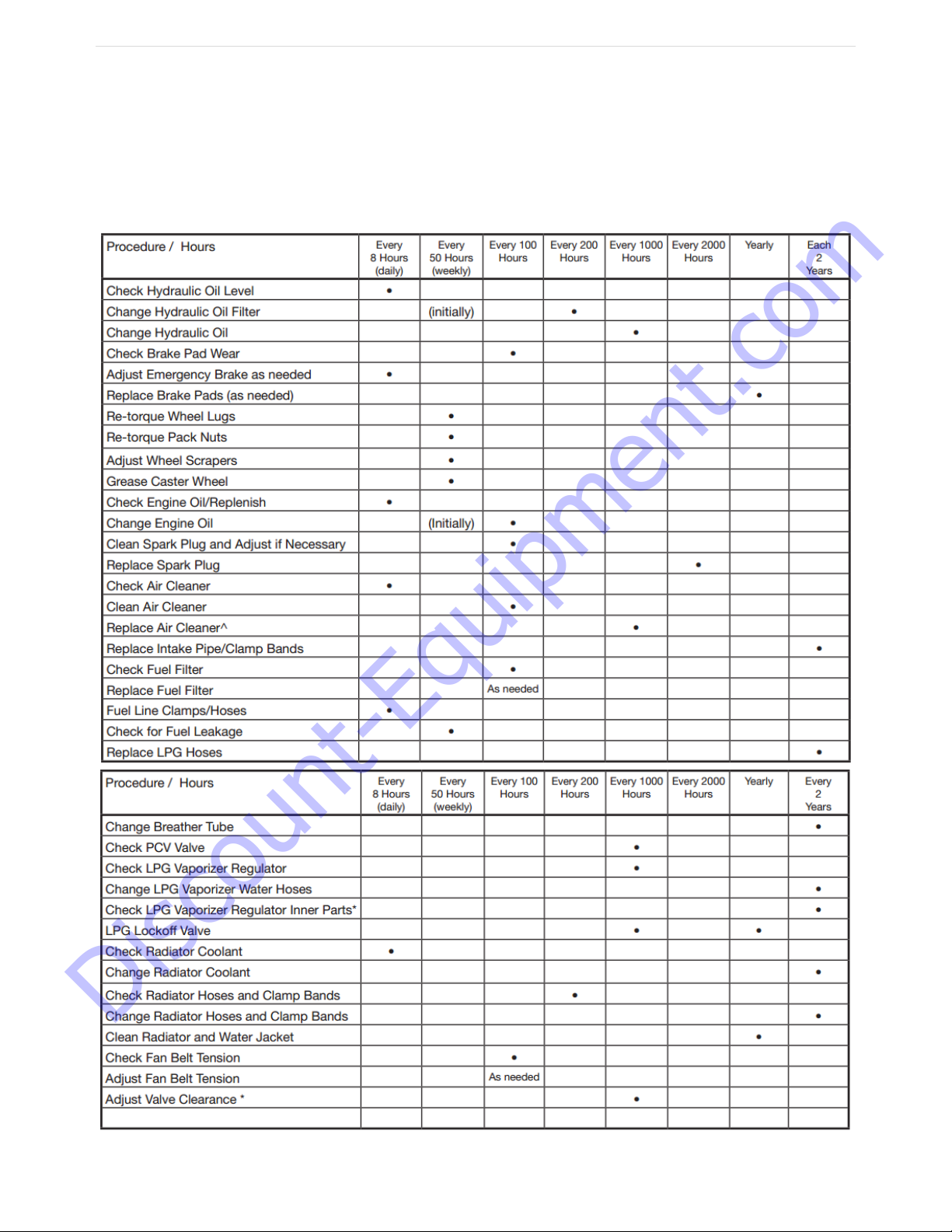
22. Maintenance Procedures
1. Change Hydraulic Oil every 18 months with NUTO H 46 or ISO 46 or if fluid is
overheated 200°F or higher.
2. Change hydraulic filter every 50 hours initially.
Discount-Equipment.com
P a g e | 18
OIPB-I03026-T2200PRO_v3.1
3. Clean Caster Wheel and Back Tires with wire wheel when necessary.
4. Look for leaks, find and tighten fittings. Do not over-tighten fittings.
5. Check all hoses and clamps once a week.
6. Inspect rear tires and lug bolts. Tighten lug bolts as needed to 70 ft.-lbs. torque.
7. Check wheel hub every 60 hours of operation. Wheel hub pack nut should be torqued
from 310 to 350 ft.-lbs.
Discount-Equipment.com

P a g e | 19
OIPB-I03026-T2200PRO_v3.1
23. Parts List
T2200 PRO Terminator
Discount-Equipment.com
Table of contents
Other Bartell Global Power Tools manuals


Popular Power Tools manuals by other brands

Ryobi
Ryobi RYHDG88 Operator's manual

Parkside
Parkside PDRS 27 A1 Translation of the original instructions

Hitachi
Hitachi NV 50AG Instruction manual and safety instructions

Dremel
Dremel 2050 Original instructions

Baileigh Industrial
Baileigh Industrial DP-1500VS Operator's manual

BTM
BTM Tog-L-Loc user guide

jcb
jcb 21-DH1300 Instructions & user's manual

Makita
Makita MAKSTAR BTW250 Series instruction manual

Silverline
Silverline 815969 Original instructions

VONROC
VONROC JS501DC Original instructions

Parkside
Parkside PBK 4 A2 Translation of the original instructions

Tohnichi
Tohnichi CL2Nx8D-MH operating instructions


