Bartell Global Contec BULL User manual

Doc. # OIPB-C15002
Orig. Rel. –11/2018
Curr. Rev. - 00
FLOOR STRIPPER
BULL
OWNER’S MANUAL AND PARTS BOOK
www.BARTELLGLOBAL.com

BULL FLOOR STRIPPER
OWNER’S MANUAL
1
OIPB –C15002
www.BARTELLGLOBAL.com
Bartell Morrison Inc.
170 Traders Blvd
Mississauga, Ontario, Canada
L4Z 1W7
Tel: (647) 953-4100
Fax: (647) 953-4101
Bartell Morrison USA LLC
200 Commerce Drive, Unit A
Freehold, NJ, USA
07728
Tel: (848) 225-8100
Fax: (848) 225-8101
SPE International Ltd
Honeyholes Lane
Dunholme, Lincoln, England
LN2 3SU
Tel: 01673 860709
Fax: 01673 861119
Innovatech
4701 Allmond Ave
Louisville, Kentucky, USA
40209
Tel: (425) 405-9100
Fax: (425) 405-9101
ORIGINAL LANGUAGE OPERATING MANUAL FOR
CONTEC FLOOR STRIPPER
© 2019 Bartell Morrison Inc.
No part of this work may be reproduced or transmitted in any form or by any means, electronic
or mechanical, including photocopying and recording, or by any information storage or retrieval
system without the prior written permission of Bartell Morrison Inc. unless such copying is
permitted by federal copyright laws.
Address inquiries or reference permissions care of:
Bartell Morrison Inc., 170 Traders Blvd., Mississauga, Ontario, Canada, L4Z 1W7
REV.
DATE
DESCRIPTION
APPROVED BY:
00
11/2018
Initial Release
AN

BULL FLOOR STRIPPER
OWNER’S MANUAL
2
OIPB –C15002
SAFETY PRECAUTIONS
DANGER
EXPLOSION HAZARD
Never operate the machine in an explosive
atmosphere, near combustible materials, or
where ventilation does not clear exhaust fumes.
CAUTION
ROTATING HAZARD
Never place hands or feet inside safety guard
rings. Serious injury will result from contact with
rotating tooling.
CAUTION
MOVING PARTS
Before starting the machine, ensure that all
guards and safety devices are in place and
functioning properly.
ATTENTION
READ OWNER’S MANUAL
Read and understand owner’s manual before
using this machine. Failure to follow operating
instructions could result in serious injury or death.

BULL FLOOR STRIPPER
OWNER’S MANUAL
3
OIPB –C15002
TABLE OF CONTENTS
QUALITY ASSURANCE/ MACHINE BREAK IN 5
WARRANTY INFORMATION 5
SPECIFICATIONS 6
PREVENTATIVE MAINTENANCE AND ROUTINE SERVICE PLAN 7
ROUTINE SERVICE SCHEDULE 8
ROUTINE SERVICE INTERVALS 8
OPERATING SAFETY PRECAUTIONS 9
OPERATION INSTRUCTIONS 10
SETTING UP YOUR BULL FLOOR STRIPPER 10
PRIOR TO OPERATION 10
CHANGING OR INSTALLING TOOLING 10
ADJUSTING THE WEIGHTS 11
OPERATION 12
PARTS LIST 1 –BULL 13
BULL FRAME –PARTS LIST 1 14
PARTS LIST 2 –BULL 15
BULL TOOLS –PARTS LIST 2 15
PARTS LIST 3 –BULL 16
BULL CONNECTING ROD –PARTS LIST 3 16
PARTS LIST 4 –BULL 17
BULL CONNECTION BRACKET –PARTS LIST 4 18
PARTS LIST 5 –BULL 19
BULL REAR WHEELS –PARTS LIST 5 19
PARTS LIST 6 –BULL 21
BULL DRIVE UNIT –PARTS LIST 6 22
PARTS LIST 7 –BULL 23
BULL HANDLE –PARTS LIST 7 24
PARTS LIST 8 –BULL 25
BULL MOTOR PROTECTION –PARTS LIST 8 26

BULL FLOOR STRIPPER
OWNER’S MANUAL
4
OIPB –C15002
PARTS LIST 9 –BULL 27
BULL DRIVE ADJUSTMENT LEVER –PARTS LIST 9 27
PARTS LIST 10 –BULL 29
BULL BEARING HOUSING –PARTS LIST 10 30
PARTS LIST 11 –BULL 31
BULL MOTOR PROTECTION –PARTS LIST 11 32
DECLARATION OF CONFORMITY 34

BULL FLOOR STRIPPER
OWNER’S MANUAL
5
OIPB –C15002
QUALITY ASSURANCE/ MACHINE BREAK IN
The Contec Floor Stripper is the product of extensive engineering development designed
to give long life and unmatched performance. The Floor Strippers are shipped completely
assembled.
You can help ensure that your Floor Stripper will perform at top levels by observing a
simple routing on first use. Consider that your new Floor Stripper is like a new car. Just as you
would break in a new car to the road or any new machine to the job, you should start gradually
and build up to full use. Learn what your machine can do and how it will respond. Full throttle
and control may be used after this time period, as allowed by material. This will serve to further
break in the machine on your specific application, as well as provide you with additional
practice using the machine.
We thank you for the confidence you have placed in us by purchasing a Contec Floor
Stripper and wish you many years of satisfied use.
WARRANTY INFORMATION
Bartell agrees to furnish without charge, F.O.B. our plant, a replacement for any part or
portion thereof, comprising the main unit of the Contec Floor Stripper, consisting of the handle,
housing assembly, save and except tooling, and power units, prove upon our examination, to
be defective in either material or workmanship within a period of twelve (12) months from date
of purchase, provided that notice of such defective part or portion thereof is given to Bartell Ltd.
within the twelve month warranty period. No further or other guarantee or warranty expressed
or implied in connection with the sale of the Floor Stripper is given and our sole liability consists
in replacing defective parts or portions thereof. We shall not be responsible for any special,
indirect or consequential damages arising in any manner whatsoever.
This guarantee is for the sole benefit of the original purchaser as end user. Our
responsibility under this guarantee ends in the case the original purchaser transfers ownership
of the Floor Stripper, makes any changes or adds any parts or devices not of our manufacture
to the Floor Stripper machine.
BULL FLOOR STRIPPER
OWNER’S MANUAL
6
OIPB –C15002
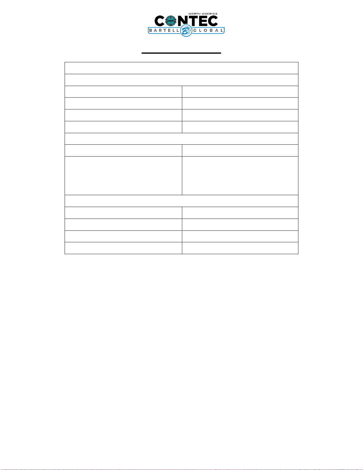
SPECIFICATIONS
BULL
Dimensions
Working Width, mm (in)
450 (17.7)
Overall Width, mm (in)
500 (19.6)
Overall Length, mm (in)
810 (31.9)
Overall Height, mm (in)
1040-1130 (41-44.5)
Weight
Weight, kg (lb)
245 (539)
Removable Weight, kg (lb)
Inboard weight
Outboard Weight
Handle Weight
107 (236)
2x 18 (40)
2x 30 (66)
11 (24)
Power Source
Power kW(hp)
1.5 (2)
Volts (V)
110
Frequency (Hz)
60
Amperage (A)
16.4

BULL FLOOR STRIPPER
OWNER’S MANUAL
7
OIPB –C15002
PREVENTATIVE MAINTENANCE AND ROUTINE SERVICE PLAN
This Contec Floor Stripper has been assembled with care and will provide years of
service. Preventative maintenance and routine service are essential to the long life of your
Floor Stripper. Your dealer is interested in your new machine and has the desire to help you get
the most value from it. After reading through this manual thoroughly, you will find that you can
do some of the regular maintenance yourself. However, when in need of parts or major service
be sure to see your Bartell dealer. For your convenience, we have provided this space to record
relevant data about your Floor Stripper. When in need of parts or service be prepared to
provide your Floor Stripper serial number. Locate the serial number now and record in the
space below.
Date Purchased:
Type of Machine:
Dealer Name:
Model:
Dealer Phone:
Serial Number:
Replacement Parts Used
Maintenance Log:
Part No.
Quantity
Cost
Date
Date
Operation

BULL FLOOR STRIPPER
OWNER’S MANUAL
8
OIPB –C15002
ROUTINE SERVICE SCHEDULE
Routine Service Intervals
Each
Use
After 1.5
months
or 50 hrs
Each 3
months
or 100
hrs
Each 6
months
or 200
hrs
Each 9
months
or 300
hrs
Each 12
months
or 400
hrs
General Inspection
Guards
Check
O
O
O
O
O
Warning Stickers
Check
O
O
O
O
O
Test Run
Check Operation
O
O
O
O
O
Fasteners
Check Tightness
O
Electrical
Cord
Check for
Damage
O
Plug
Check for
Damage
O
Switches/Buttons
Check
O
Components
Tooling
Check Life
O
Tooling Holder
Check for
Damage
O
Motor
Fan
Check - Clean
O
O
O
O
O
ROUTINE SERVICE INTERVALS
Due to the nature and environment of use, Floor Strippers could be exposed to severe
operating conditions. Some general maintenance guidelines will extend the useful life of your
machine.
• The initial service for your floor stripper should be performed after 25 hours of use, at which
time your mechanic (or authorized repair shop) should complete all the recommended checks
in the schedule above. The maintenance log is handy for keeping a record of the maintenance
performed and the parts used for servicing your grinder.
• Regular service according to the schedule above will prolong the life of the floor stripper and
prevent expensive repairs.
• Keeping your floor stripper clean and free from debris is the single most important regular
maintenance operation, over and above the checks in the service schedule above, that can be
performed. After each use your floor stripper should be cleaned to remove any dust and debris
from the undercarriage and surrounding components.
• In the Service Schedule above, items that should be checked, replaced or adjusted are
indicated by “o” in the appropriate column. For ease of recording place, a checkmark through
the “o” when the item is complete. If an item is not required or not completed place an “x”
through the “o” in the box.
• Failure to have your floor stripper regularly serviced and properly maintained in accordance
with the manufacturer’s instructions will lead to premature failure and void the warranty.

BULL FLOOR STRIPPER
OWNER’S MANUAL
9
OIPB –C15002
OPERATING SAFETY PRECAUTIONS
The BULL floor strippers are constructed according to existing safety rules and
regulations. These technical precautions should not be removed or changed under any
circumstances. While operating the machines the following points should also be kept in mind:
The instructions provided in this manual are done so to ensure the operator’s safety as well
as that of others, the equipment, and the job site. Failure to follow these guidelines can lead to
serious personal injury and even death. The operator and any service personnel should read
and understand the entire manual before working with or servicing any Contec Floor Stripper.
•The floor stripper BULL should always be operated with all safety covers and technical
precautions.
•During transport, cleaning, repair or maintenance the floor stripper must be disconnected
from the power supply. This also applies to the changing of tools.
•Always remove the tool before transporting the machine.
•Only use tools delivered by CONTEC®.
•The operator should never leave the machine unattended during operation.
•Before leaving the machine, all rotary parts should be brought to a standstill. The floor
stripper must be disconnected from the power supply. Make sure that the machine
cannot roll or move by itself.
•The BULL should be switched off immediately if unusual noises or vibrations are
detected during the operating of the machinery. A thorough check must be carried out in
order to detect the cause.
•After any maintenance and adjustment all safety covers must be reattached.
•Ear protectors must be worn.
•Eye protectors must be worn.
•Safety shoes with steel caps must be worn.
•In the event of a large amount of dust during operation, connect a dust collector to the
grinder.
•Depending on the type of floor (floor coating) stripping can produce gases/dust. The
operator must be held responsible if these generated gases/dusts are dangerous and if
protection is necessary. Stripping floors containing asbestos is especially dangerous and
can cause health problems. Special masks must be worn which keep the breathing air
clean. A dust collector must be used and should be equipped with filters suitable for
asbestos dust.
The floor must be swept before stripping. Anchor screws and bolts coming out of the floor can
be better seen if the floor is clean. If the stripping tool strikes an anchor screw or bolt, then
serious damage can be caused to the machine or grinding head.

BULL FLOOR STRIPPER
OWNER’S MANUAL
10
OIPB –C15002
OPERATION INSTRUCTIONS
SETTING UP YOUR BULL FLOOR STRIPPER
Your BULL Floor Stripper comes fully assembled with handle and motor fully installed.
The handle is in the lowest position to allow for easier transportation. The handle can be
adjusted to suit the operator by loosening the 2 screws at the base of the handle and
retightening to set position. Tooling can now be installed, and your Floor stripper is ready for
use.
PRIOR TO OPERATION
•Make sure that all dust, debris etc., are thoroughly removed from the unit prior to
operation. Special effort should be given to the bottom of the machine where the tooling
is located, as well as the drive wheels and motor.
•Check all bolts and screws for tightness and make sure all bolts and screws are securely
tightened. Loose bolts and screws may cause damage to the unit. Make sure tooling is
properly installed.
CHANGING OR INSTALLING TOOLING
•Lock the centre weights into position 1 (See below “Adjusting the Weights”)
•Tip the machine until it rests in a stable position
•Clean and loosen the bolts of the blade mounting
•Replace the blade.
•Make sure that the blade fits exactly into the support. On normal and hard subfloors, the
bevel of the blade should show upwards (B). On soft subfloors the bevel should show
downwards (A).
Figure 1: Blade orientation
•Tighten the bolts of the blade mounting again
ATTENTION: Before working on the floor stripper bring the motor to a total stand still
and disconnect from the power supply.
CAUTION: Tooling is sharp, set wrench in position opposite to blade to avoid injury
BULL FLOOR STRIPPER
OWNER’S MANUAL
11
OIPB –C15002
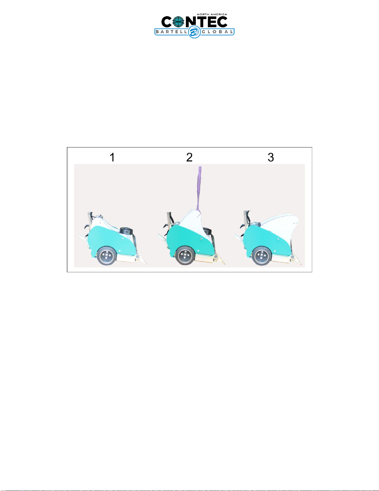
ADJUSTING THE WEIGHTS
The two centre weights can be locked in three different positions. The locking bolt is situated on
the right-hand side outside the weight. The bolt must be pulled out before changing the
position.
Pos. 1: the weight is mostly on the rear traction wheels. The wheels will have increased traction
and drive is increased.
Pos. 2: The weight is in the middle position and creates an option to transport machine with a
crane.
Pos. 3: The weight is mostly on the tool. The tools will be less likely to jump up and slide on top
of the material trying to be removed.
Figure 2: Weight positioning

BULL FLOOR STRIPPER
OWNER’S MANUAL
12
OIPB –C15002
OPERATION
Operating
The Bull-Stripper removes any bonded floor covering by using a vibrating knife. The knife is
driven by an electric motor.
The drive unit is powered by a separate motor.
The blade drive starts as soon as the machine is switched on and can easily be switched off by
pressing the emergency stop switch or the red OFF switch. The drive unit motor starts by
pressing the safety switch on the handle bar. If the handle bar is pushed forward the drive unit
starts to work, and the machine starts to move. The drive can be locked in the moving position
by stepping on the foot lever at the bottom of the handle bar.
The Bull-Stripper is equipped with a power-on indicator lamp. If the lamp does not indicate
power-on, use another power socket or check power supply.
If a supply power failure occurs during operation, switch the machine on again.
Preparations (Carpets, Coverings)
Before starting work, cut the floor covering into strips of about 35 cm (12 inch). You cannot
work faster if you cut wider strips.
To begin, cut one strip crosswise. Then lift the floor covering slightly in order to get the blade
underneath it. We recommend that you cut the first strip at right angles to the main working
direction. By so doing access to the adjacent strips is made easier.
Cut the strips smaller if the floor covering is bonded very securely, e.g. with an epoxy adhesive.
The blades are sharpened by the floor pavement. Therefore, the blade only has to be changed
if it is twisted, rounded or becomes worn.
The driving wheels are subject to wear. They have to be changed when necessary.

BULL FLOOR STRIPPER
OWNER’S MANUAL
13
OIPB –C15002
PARTS LIST 1 –BULL
Figure 3: BULL Frame

BULL FLOOR STRIPPER
OWNER’S MANUAL
14
OIPB –C15002
BULL FRAME –PARTS LIST 1
Item #
Part #
Description
QTY
Remarks
1
8761200130
Linear bearing housing
2
4
8727101500
Fender Motor
1
5
87LBCD30A2LS
Linear-Bearing
4
6
8727100100
Main Plate
1
12
8727103204
Connection bracket
1
18
8761210130
Grease Nipple
2
24
87612030201
Sealing
4
30
8770261800
Bracket for Rubber Block
2
69
8727100900
Bracket for Drive Adjustment
1
89
8761411050
Tension Spring
1
207
8705421812
Hose clamp
2
208
8761300147
Circlip
4
223
8761330019
Washer, M6
11
228
8761310017
Screw, Hexagon M8x16
19
229
8761330018
Spring Washer M8
10
230
8761330006
Washer M8
12
246
8761310052
Screw, Allen M12x65
4
247
8761310025
Screw, Hexagon M8x40
2
248
8761310013
Screw, Hexagon M8x25
6
249
8761320005
Nut M8
2
250
8761320002
Sliding nut M8
4
251
8761310023
Screw, Allen M6x16
5
252
8761330012
Spring Washer M6
3
BULL FLOOR STRIPPER
OWNER’S MANUAL
15
OIPB –C15002
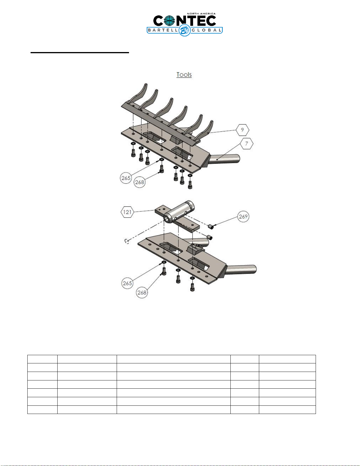
PARTS LIST 2 –BULL
Figure 4: BULL Tools
BULL TOOLS –PARTS LIST 2
Item #
Part #
Description
QTY
Remarks
7
8727101200
Blade Holder
1
9
8727101703
Bracket for Blade 350mm
1
121
8727101800
Chisel Holder
1
265
8761330016
Washer, Serrated M8
6
268
8761310006
Screw, Allen M8x20
5
269
8761340007
Threaded pin M8x10
2

BULL FLOOR STRIPPER
OWNER’S MANUAL
16
OIPB –C15002
PARTS LIST 3 –BULL
Figure 5: BULL Connecting Rod
BULL CONNECTING ROD –PARTS LIST 3
Item #
Part #
Description
QTY
Remarks
13
8747280
Circlip
1
17
876160102ZC3
Bearing
3
19
8727101604
Connecting Rod
1
20
8784833080
Slide bush 20mm
1
22
8784832315
Slide bush 15mm
3
BULL FLOOR STRIPPER
OWNER’S MANUAL
17
OIPB –C15002
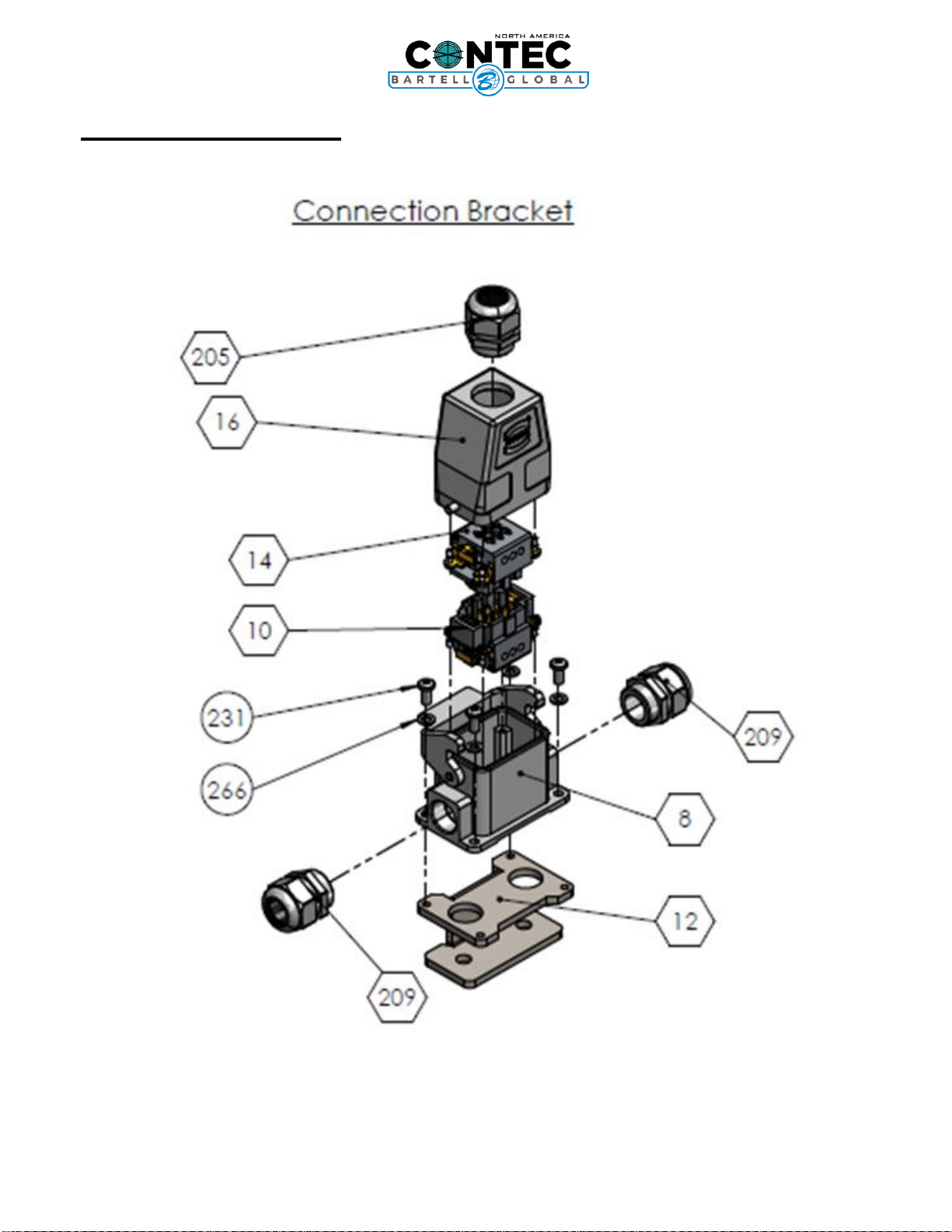
PARTS LIST 4 –BULL
Figure 6: BULL Connection Bracket

BULL FLOOR STRIPPER
OWNER’S MANUAL
18
OIPB –C15002
BULL CONNECTION BRACKET –PARTS LIST 4
Item #
Part #
Description
QTY
Remarks
8
87212313
Plug Housing
1
10
87502020131
Plug Pin Mounting
1
12
8727103204
Connection bracket
1
14
87502020121
Jack in the Housing
1
16
8750202013
Socket housing
1
205
87502023M25
Cable Gland
4
209
87502023M25MS
Cable Gland
2
231
8761310062
Screw, Skt. Button Hd. M5x12
5
266
8761330042
Washer, Serrated M5
4

BULL FLOOR STRIPPER
OWNER’S MANUAL
19
OIPB –C15002
PARTS LIST 5 –BULL
Figure 7: BULL Rear Wheels
BULL REAR WHEELS –PARTS LIST 5
Item #
Part #
Description
QTY
Remarks
21
8727101605
Wheel axis
1
23
8780202051
Drive Wheel
1
25
8761206004
Bearing
4
27
8727101607
Collar
2
29
8780202050
Binding Wheel
2
228
8761310017
Screw, Hexagon M8x16
19
235
8761330038
Washer, M12
12
251
8761310023
Screw, Allen M6x16
5
252
8761330012
Spring Washer M6
3
259
8761330041
Washer, Wide 6,4x25
2
260
8761310064
Screw, Hexagon M12x35
8
261
8761330009
Spring Washer M12
8
259
8761330041
Washer, Wide 6,4x25
2
Table of contents
Other Bartell Global Power Tools manuals


