MDI MD500T User manual

USE AND CARE GUIDE
SUBMERSIBLE SEWAGE PUMP
Model # MD500T
MD500T-G
MD500T-V
MD500T-G SHOWN

DESCRIPTION
This submersible sewage pump is designed for pumping sewage, effluent, wastewater or flooded water with up
to two-inch solids. The pump is built with overload thermal protections and auto reset. Ball bearings on motor
shafts never need lubrication.
The MD500T is equipped with a 10’ 3-prong grounding-type power cord pump is a manual pump, a switching
device is required.
The MD500T-G is equipped with a 10’ 3-prong grounding-type power cord and tethered float switch.
The MD500T-V is equipped with a 10’ 3-prong grounding-type power cord and vertical float switch.
The MD500T-G and MD500T-V pumps operate automatically.
This pump has not been tested or approved for use in swimming pools or in salt-water marine areas. It is also
not engineered to be run continuously as a “fountain” or “waterfall” pump.
Do not pump flammable or explosive liquids such as oil, gasoline, kerosene, ethanol, etc. Do not
use in the presence of flammable or explosive vapors. Using this pump with or near flammable
liquids can cause explosion or fire, resulting in serious personal injury or death and/or property
damage.
SPECIFICATIONS
Power supply required ................................................................................. 115V, 60 HZ
Water temperature range ............................................................................ Max.190°F (88°C)
Individual branch circuit required ................................................................ 15 Amp minimum
Discharge Connection ................................................................................. 2” FNPT
Motor duty ................................................................................................... Continuous
Power cord .................................................................................................. SJTW 18AWG/3C, 10ft
NOTICE: This unit is not designed to be used to pump salt water or brine! Use with salt water or brine
will void warranty.
CONSTRUCTION
Motor housing ..................................................................................... Cast Iron
Motor cap ............................................................................................ Cast Iron
Volute .................................................................................................. Cast Iron
Impeller ............................................................................................... Reinforced thermoplastic vortex
2
Warning

SAFETY INSTRUCTIONS
Please read and understand this entire manual before attempting to assemble, operate or install the product.
Failure to comply with instructions and designed operation of this system may void warranty. ATTEMPTING TO
USE A DAMAGED PUMP can result in personal injury or death!
Safety Precautions
1. Know the pump applications, limitations, and potential hazards.
2. Do not lift pump by power cord or switch cord.
3. Do not touch an operating motor housing. The motor is designed to operate at high temperatures.
4. Do not disassemble the motor housing. Motor has been filled at the factory with special oil. In normal service,
motor should not need oiling. The motor has NO repairable internal parts, and disassembling it may cause
oil leakage or dangerous electrical wiring issues.
5. Make certain the electrical power source is adequate for the requirements of the pump.
6. ALWAYS disconnect the power to the pump before servicing.
7. Release all pressure within system before servicing any component.
8. Drain all water from system before servicing.
9. Secure discharge line before starting pump. An unsecured discharge line will whip, possibly causing
personal injury and/or property damage.
10. Secure the pump on a solid base to keep the pump vertical and above mud and sand during operation to
maximize pumping efficiency and prevent clogging and premature pump failure.
11. Check that all pipe connections are tight to minimize leaks.
12. Connect the pump DIRECTLY to a grounded, GFCI outlet.
13. Extension cords may not deliver sufficient voltage to the pump motor. Extension cords present a life
threatening safety hazard if the insulation becomes damaged or the connection ends fall into water.
14. Make certain the electrical circuit to the pump is protected by a 15 Amp or larger fuse or circuit breaker.
15. Periodically inspect the pump and system components. Perform routine maintenance as required. Do
not handle pump or pump motor with wet hands or when standing on wet or damp surface, or in water.
16. Wear safety glasses at all times when working with pumps.
17. Follow all electrical and safety codes, particularly the Canadian Electrical Code, and local codes and
ordinances.
18. This unit is designed only for use on 115 volts (single phase), 60 Hz, and is equipped with an approved
3-conductor cord and 3-prong grounded plug. DO NOT REMOVE THE GROUND PIN UNDER ANY
CIRCUMSTANCES. The 3-prong plug must be directly inserted into a properly installed and grounded
3-prong, grounding-type receptacle. Do not use this pump with a 2-prong wall outlet. Replace the
2-prong outlet with a properly grounded 3-prong receptacle (a GFCI outlet) installed in accordance with
the Canadian Electrical Code and local codes and ordinances. All wiring should be performed by a
qualified electrician.
19. Protect the electrical cord from sharp objects, hot surfaces, oil, and chemicals. Avoid kinking the cord. Do
not use damaged or worn cords.
3

INSTALLATION
Materials required: 2" PVC pipe with cement to match and in-line check valve. Be sure to install the check
valve so that the flow will be away from the pump.
1. Install the pump on a solid, level foundation, or in a sump pit constructed of tile, concrete, steel, or plastic.
The recommended minimum diameter of the sump pit is 18" (46 cm) diameter and the minimum
recommended depth is 30" (76 cm). Check local codes for approved materials.
NOTICE: Pump should not be installed on clay, earth, or sand surfaces.
2. Clean the area around the pump of small stones and gravel which could clog the pump. Keep the pump
inlet screen clear.
3. Secure the pump on a level, solid base. Do not suspend the pump by the discharge pipe, hose, or power
cord.
4.
5. To reduce motor noise and vibrations, a short length of rubber hose can be connected into discharge line
near pump using suitable clamps.
6. If the pump discharge line is exposed to outside subfreezing atmosphere, then the portion of line exposed
must be installed so any water remaining in pipe will drain to outfall by gravity. Failure to do this can cause
water trapped in discharge to freeze, which could result in damage to pump.
7. Install a check valve in the pipe to prevent flow backwards through the pump when it shuts off. Make certain
the flow indicating arrow points away from the pump. This check valve will keep the water from either
running back into the basin or into the area being pumped out when the pump is not running. Check valve
should be a free flow valve that will easily pass solids.
NOTICE: For best performance of check valve when handling solids, do not install it with discharge angled
more than 45° above the horizontal. Do not install check valve in a vertical position as solids may settle in
valve and prevent opening on startup.
8. Drill a 1/8” (3.1 mm) hole in discharge pipe about 1"-2” (2.5 - 5.1 cm) above pump discharge connection to
prevent air-locking the pump.
9.
10. After the installation of the necessary plumbing, check valve, and rubber hose, follow the glue
manufacturer’s instructions for safety precautions and curing time. The pump is ready for operation.
11. Pump is designed for 115 V, 60 Hz, operation and requires a minimum 15-amp individual branch circuit.
12.
4
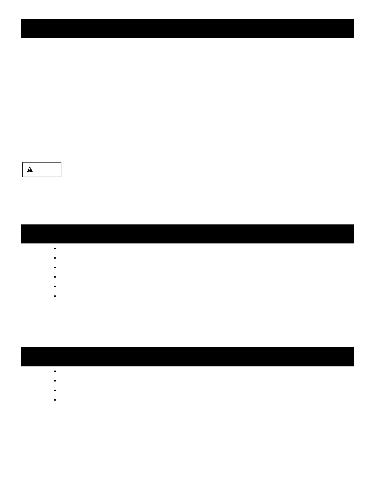
Install 2” discharge pipe into the 2” NPT discharge port. Use rigid plastic pipe and wrap threads with Teflon
tape, NOT pipe joint compound. Screw pipe into pump hand tight plus 1-1/2 turns.
Check the pump by filling the sump pit with water and observe the pump’s operation through one complete
cycle. Make sure the pump cannot move in the sump and float switch moves freely up and down.
For tethered piggyback float switch mounting. The length of the tether (distance of cord from float to clamp)
should be set around 3.5 inches (pre-set on the MD500T-G and MD500T-V) and should not be used in a
basin smaller than 18 inches in diameter. If using a differential other than the factory setting, be sure when
the pump shuts off at least 4.5” of fluid is left in the basin so the impeller remains submerged. Insert the
float switch piggy-back plug into a properly grounded outlet and the pump plug into the piggyback plug.

OPERATION
WARNING: Do not handle this pump or plug in or unplug this pump with wet hands or while standing in water,
unless you are certain all power has been turned off to the pump. Remember, the pump should be connected
only to a properly grounded, GFCI outlet.
1. Make certain the pump is submerged in water. Running the pump dry can damage the shaft seal.
2. Plug the pump into a 115V GFCI power outlet. The pump will start operating when the float switch moves
up over the pump top. The water will be pumped out. When the water lowers to certain level, the float switch
will turn off the pump.
3.
NOTICE: If the overload protector stops the pump repeatedly, disconnect the power from the pump and check
to find the problem. Low voltage, a long extension cord, clogged impeller, screen blocked by debris, or water
that is too hot can cause motor overheating.
5
The motor is equipped with an automatically resetting thermal overload protector. If the motor gets too hot,
the overload protector will shut off the pump before it is damaged. When the motor has cooled sufficiently,
the overload protector will reset, and the motor will restart.

TROUBLESHOOTING GUIDE CHECKLIST
Do notdisassemble the motor housing. This motor has NO repairableinternal parts, and disassembly
may cause an oil leak ordangerous electrical wiring issues. DO NOT lift up the pump bypower cord.
Problem Possible Cause Corrective Action
Pump does not start
or run 1. Blown fuse
2. Tripped breaker
3. Plug disconnected
4. Corroded plug
5. Thermal overload
6. Clogged impeller
7. Motor failed
8. Float failed
9. Water level too low
10.Tangled switch
Replace fuse
Reset breaker
Secure plug
Clean plug prongs
Unplug for 30 minutes, then plug in
Remove clog
Replace pump
Replace switch
Pump will not turn on unless water level
is over the pump cover and the float
switch turns upside down
Reposition the pump and make sure
switch moves freely
Pump operates but
pumps little or no
water
1. Debris caught in impeller or pipe
2. Check valve stuck or installed
backward
3. Anti-airlock hole blocked
4. Impeller loose on shaft
5. Impeller broken
Clean out debris
Inspect check valve and make sure it’s
properly installed
Remove the blockage
Reassemble impeller
Replace impeller
Pump starts and
stops too often 1. Back-flow of water from piping,
check valve leaking
2. Float switch failed
Pump will not shut off 1. Defective float switch
2. Float obstructed 1. Replace switch
2. Remove obstruction
6
1.
2.
3.
4.
5.
6.
7.
8.
9.
10.
1.
2.
3.
4.
5.
1. Replace check valve
2. Replace switch

LIMITED WARRANTY
This Limited Warranty applies to residential pumps sold under only the MDI brand.
MDI – Mercury Displacement Industries
25028 US 12 EAST
Edwardsburg, MI 49112
1-800-634-4077
88403-01
MDI warrants to the original purchaser (“Purchaser” or “You”) of MDI series pumps that they will be free from
defects in material and workmanship for the Warranty Period of 36 months from date of purchase. The date of
purchase shall be determined by the original dated sales receipt noting the model and serial number of the pump.
The original sales receipt must accompany the returned pump.
MDI shall not be liable under this Warranty for any product that, in our sole judgment, has been subject to
negligence, misapplication, improper installation, or improper maintenance. Also, MDI shall not be liable under
this Warranty if the product has been disassembled, modified, abused or tampered with; if the electrical cord has
been cut, damaged or spliced; if the pump discharge has been reduced in size; if the pump has been used in
water temperatures above the advertised rating, or water containing sand, lime, cement, gravel or other
abrasives; if the product has been used to pump chemicals or hydrocarbons; or if the label bearing the pump
model and serial numbers has been removed.
Your sole remedy and MDI’s only duty is that MDI repair or replaces defective pumps (at MDI’s choice). You must
pay all labor and shipping charges associated with this warranty and must request warranty service through the
installing dealer as soon as the problem is discovered. No request for service will be accepted if received after
the Warranty Period has expired. This warranty is non-transferable.
Some states do not allow the exclusion or limitation of incidental or consequential damages or limitations on the
duration of the implied warranty, so the above limitations or exclusions may not apply to you. This warranty gives
you specific legal rights and you may also have other rights which may vary from state to state. This warranty
applies to only MDI pumps installed in the United States of America and Canada.
This warranty supersedes and replaces all previous warranty publications.
The foregoing warranties are exclusive and in lieu of all other express and implied warranties, including
but not limited to the implied warranties of merchantability and fitness for a particular purpose. The
forgoing warranties shall not extend beyond the duration expressly provided herein.
MDI shall not be liable for any consequential, incidental, or contingent damages whatsoever. MDI
recommends using a professional plumber for all installation and repair and periodic inspection of MDI
pumps. MDI makes no warranty regarding the suitability of a product for a particular installation.
Purchasers are responsible for determining whether a pump is suitable for a specific application.
This manual suits for next models
2
Table of contents
Popular Water Pump manuals by other brands

Sunforce
Sunforce 80 WATT SOLAR WATER PUMP user manual

GORMAN-RUPP PUMPS
GORMAN-RUPP PUMPS T4A65-B Installation, operation and maintenance manual

AFL
AFL 30GHR Operating & maintenance instructions

Alaris
Alaris GW 800 Series Directions for use

AL Tech
AL Tech IRYD 25-40-70/180 user manual

Care Fusion
Care Fusion Alaris SE user manual