Bartels Mikrotechnik mp6 User manual

Bartels Mikrotechnik GmbH,
Otto
-
Hahn
-
Str.
15
, 44227 Dortmun , Germany
www.micro-components.com, microComponents@bartels-mikrotechnik. e
Tel: +49-231-9742-500, Fax: +49-231-9742-501
Last update: 15.0
5
.2013
Operating Manual
Micropump mp6/mp6-pp
and Controller

2
Bartels Mikrotechnik GmbH,
Otto
-
Hahn
-
Str.
1
5
, 44227 Dortmun , Germany
www.micro-components.com, microComponents@bartels-mikrotechnik. e
Tel: +49-231-9742-500, Fax: +49-231-9742-501
Table of contents
1. General ......................................................................................................................................... 4
1.1 Declaration o con ormity .......................................................................................................................... 4
1.2 Description o unctions ............................................................................................................................. 4
2. Proper use ................................................................................................................................... 5
2.1 Intended purpose .......................................................................................................................................... 5
2.2 Misuse ............................................................................................................................................................... 5
2.3 Sta selection and quali ication .............................................................................................................. 5
2.4 About this operating manual .................................................................................................................... 5
3. Technical specifications .............................................................................................................. 6
3.1 Technical speci ications mp6
1
................................................................................................................. 6
3.2 Technical speci ications mp6-pp
1
.......................................................................................................... 7
3.3 Typical low characteristics mp6 and mp6-pp .................................................................................... 8
3.4 Final inspection .............................................................................................................................................. 8
4. Operating the micropump ........................................................................................................10
4.1 Connecting the micropump ..................................................................................................................... 10
4.1.1 Connecting the mp6/mp6-pp to the cable ................................................................................ 11
4.2 Cleaning the system ................................................................................................................................... 12
4.3 Typical operation parameters .................................................................................................................. 13
4.3.1 mp6 ......................................................................................................................................................... 13
4.3.1.1 Medium: Dl water ........................................................................................................................... 13
4.3.1.2 Medium: air ....................................................................................................................................... 14
4.3.2 mp6-pp .................................................................................................................................................. 14
4.3.2.1 Medium: Dl water ........................................................................................................................... 14
5. The mp- controller ..................................................................................................................16
5.1 Technical speci ications mp-x controller ............................................................................................ 16
5.2 Electrical signal orm ................................................................................................................................. 17
5.3 Connecting the pump to the mp-x ....................................................................................................... 18
5.4 Operation o the mp-x............................................................................................................................... 19

3
Bartels Mikrotechnik GmbH,
Otto
-
Hahn
-
Str.
1
5
, 44227 Dortmun , Germany
www.micro-components.com, microComponents@bartels-mikrotechnik. e
Tel: +49-231-9742-500, Fax: +49-231-9742-501
5.5 Installation o the drivers “USB Micropump Control” and “USB Serial Port” .......................... 20
5.5.1 For older operating systems including “Windows XP” ............................................................ 20
5.5.2 For operating system Windows 7 .................................................................................................. 20
5.6 Operation via USB port (a ter installation o the drivers) ............................................................. 20
6.1 Technical speci ications mp6-OEM ....................................................................................................... 22
6.2 Typical low characteristics mp6............................................................................................................ 22
6.3 Connecting the mp6 to the mp6-OEM controller ............................................................................ 23
6.4 Typical schematics ...................................................................................................................................... 23
6.4.1 Fixed pump rate .................................................................................................................................. 23
6.4.2 Pump rate set by external components ....................................................................................... 23
6.4.3 Pump rate control via microcontroller ........................................................................................ 25
6.5 Electrical characteristics ........................................................................................................................... 26
6.6 Pin description ............................................................................................................................................. 26
6.7 Noise reduction ............................................................................................................................................ 26
7. The mp6-EVA evaluation board ...............................................................................................27
7.1 Sa ety notice ................................................................................................................................................. 27
7.2 Electrical speci ications mp6-EVA evaluation board ....................................................................... 27
7.3 Functional elements ................................................................................................................................... 27
7.4 Operation ....................................................................................................................................................... 28
7.4.1 Pump requency setting with jumper J1 ..................................................................................... 28
7.4.2 Pump amplitude setting with jumper J2..................................................................................... 28
7.4.3 Operation voltage setting with jumper J3 .................................................................................. 29
7.5 Connecting the pump via CON2 ............................................................................................................. 29
8. Passive check valve mp-cv .......................................................................................................30
9. Trouble shooting .......................................................................................................................31
.

4
Bartels Mikrotechnik GmbH,
Otto
-
Hahn
-
Str.
1
5
, 44227 Dortmun , Germany
www.micro-components.com, microComponents@bartels-mikrotechnik. e
Tel: +49-231-9742-500, Fax: +49-231-9742-501
1. General
This operating manual contains all necessary instructions or the installation, commissioning, operation and
maintenance o the mp6 and mp6-pp micropump and o the controller mp-x, mp6-OEM and mp6-EVA with
the mp6 and mp6-pp.
The unit has been designed with state-o -the-art technology and in accordance with all relevant sa ety
regulations. However, a risk o damage to the units, other property, the operator and/or other persons
cannot be ully excluded.
Always comply with the ollowing general instructions:
•Be ore working with a pump, you must be ully amiliar with its operation and unctions.
•Prior to operating the pump, read this operating manual and adhere to all instructions.
•Re rain rom any operations that might endanger the sa ety o the unit.
Bartels Mikrotechnik GmbH rejects any responsibility or damages to persons or property resulting rom
non-compliance with the instructions in this manual. In this case all warranties shall be void.
1.1 Declaration of conformity
Bartels Mikrotechnik GmbH is certi ied according to DIN EN ISO 9001:2000 and declares that the products
are compliant to the RoHS directive and the controller comply with the requirements o EMC 89/336/EEC
and CE markings have been a ixed to the devices.
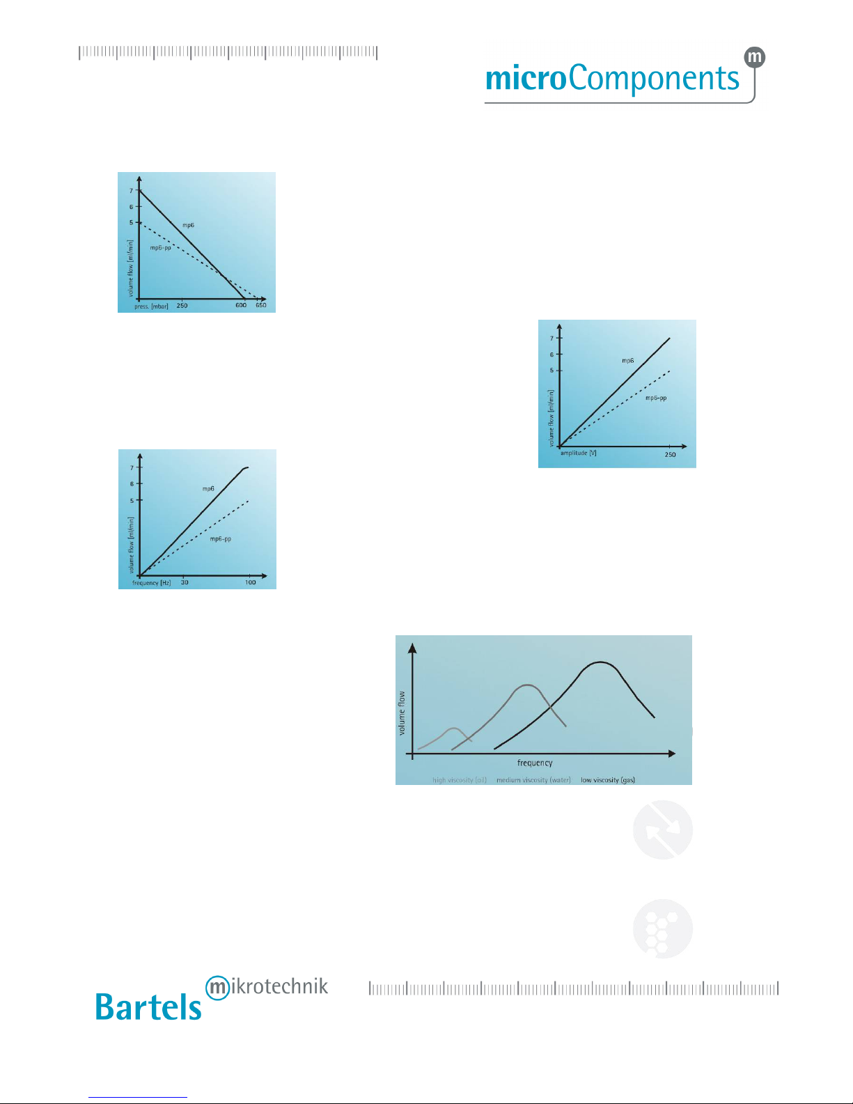
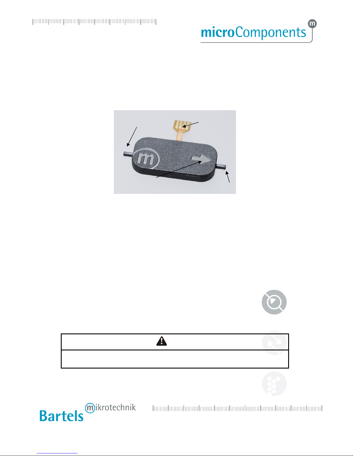
1.2 Description of functions
The micropumps have been developed or the transport o gases or liquids. The mp-x controller, the mp6-a
controller, mp6-OEM and mp6-EVA controller have been developed or operating one mp6 or one mp6-pp.
Bartels Mikrotechnik can assume no liability or damages resulting rom the pump media. This applies
especially or hazardous luids.
The pumps must be operated with Bartels Mikrotechnik electronics. Bartels Mikrotechnik GmbH cannot
guarantee the proper work o the units with customer speci ic electronics. I other controllers than the ones
rom Bartels Mikrotechnik are used, Bartels Mikrotechnik disclaims any warranty.
Please make sure that only skilled personnel works with the pump control and micropump. The micropump
shall be under constant supervision at running conditions. And please note that components o the
controller and pump are operating with high-voltage. There ore persons wearing pacemakers are
recommended to avoid the operating system.
Bartels Mikrotechnik assumes no liability or abnormal handling, improper or negligent use o the
micropump and the controller that is not con orm to the speci ied purpose o the system. This applies
especially or micropump controllers, components and systems o other manu acturers, which have not
been certi ied by Bartels Mikrotechnik.
We guarantee that the micropumps comply with the actual state o scienti ic and technical knowledge and
due to this the operational risks are limited to a minimum.
Do not open the housing o the micropump and the controllers. In those cases Bartels Mikrotechnik can not
issue a guaranty anymore. Please keep this manual sa e and give a copy to all users.

5
Bartels Mikrotechnik GmbH,
Otto
-
Hahn
-
Str.
1
5
, 44227 Dortmun , Germany
www.micro-components.com, microComponents@bartels-mikrotechnik. e
Tel: +49-231-9742-500, Fax: +49-231-9742-501
2. Proper use
2.1 Intended purpose
The micropump is intended or pumping liquids or gases with varying low rates controlled by the
electronics. The mp-x, the mp6-a, mp6-OEM and mp6-EVA controllers are intended or operating one mp6
or one mp6-pp. Any other use o the micropump or controller unit is deemed improper.
Do not make any modi ications or extensions to the pump or controller without the prior written consent o
the manu acturer. Such modi ications may impair the sa ety o the unit and are prohibited. Bartels
Mikrotechnik GmbH rejects any responsibility or damage to the unit caused by unauthorized modi ications
to the pump and risk and liability are automatically trans erred to the operator.
2.2 Misuse
The use o liquids, which may alone or in combination create explosive or otherwise health-endangering
conditions (including vapors) is not permitted.
2.3 Staff selection and qualification
All work in connection with the installation, assembly, commissioning/decommissioning, disassembly,
operation, servicing, cleaning and repairing o the pump and the controller must be carried out by quali ied,
suitably trained and instructed personnel.
Work on electrical components and assemblies must be carried out by personnel with the necessary
quali ications and skills.
2.4 About this operating manual
Warnings and important notes are clearly identi ied as such in the text. The relevant text sections eature a
speci ic sign. However, this icon cannot replace the sa ety instructions. There ore, care ully read all sa ety
instructions in this manual. Warnings and important notes in this text are highlighted as shown below,
according to the severity o the damage that might result rom non-compliance.
DANGER
DANGER INDICATES A HAZARD WITH A HIGH LEVEL OF RISK WHICH, IF NOT AVOIDED, WILL
RESULT IN DEATH OR SERIOUS INJURY.

6
Bartels Mikrotechnik GmbH,
Otto
-
Hahn
-
Str.
1
5
, 44227 Dortmun , Germany
www.micro-components.com, microComponents@bartels-mikrotechnik. e
Tel: +49-231-9742-500, Fax: +49-231-9742-501
3. Technical specifications
3.1 Technical specifications mp6
1
mp6
Order code: mp6
Pump type
piezoelect
ric diaphragm pump
Number o actuators
2
Dimensions without connectors
30 x 15 x 3.8 mm³
Weight
2 g
Fluidic connectors
barbed tube clip (outer diameter
1.9 mm, length 3.5 mm)
2
Electric connector
lex connector / Molex FCC
1.25 mm pitch
Power consum
ption
< 200 mW
Sel
-
priming
yes
3
Pumping media
liquids, gases and mixtures
Operating temperature
0
–
70°C
Li e time
5000 h
4
IP code
IP33
5
Materials in contact with media
polyphenylene sulphone (PPSU)
6
Suitable evaluation controller
mp
-
x, mp6
-
EV
A and mp6
-
OEM
Typical values o low and back pressure or selected media
(values de ined with mp-x: 250 V, SRS):
Gases
Max. low
18 ml/min (300 Hz)
Max. back pressure
100 mbar (300 Hz)
Liquids
Water
Max. low
7 ml/min +/
-
15% (100 Hz)
Max. back
pressure
600 mbar +/
-
15% (100 Hz)
1
Typical values. Values can vary under application conditions.
Content is subject to changes without notice.
2
recommended tubing: 1.3 mm inner diameter.
3
Conditions: suction pressure < 10 mbar, DI water, settings mp-x: 100 Hz, 250 V, SRS, the max. low rate will be reached a ter a ew minutes o
operation time.
4
Conditions: DI water, room temperature, settings mp-x: 100 Hz, 250 V, SRS.
5
Can be changed to IP44.
6
The mp6 is not stable against concentrated alcoholic solutions as MeOH or EtOH.

7
Bartels Mikrotechnik GmbH,
Otto
-
Hahn
-
Str.
1
5
, 44227 Dortmun , Germany
www.micro-components.com, microComponents@bartels-mikrotechnik. e
Tel: +49-231-9742-500, Fax: +49-231-9742-501
3.2 Technical specifications mp6-pp
1
mp6
-
pp
Order code: mp6
-
pp
Pump type
piezoelectric diaphragm pump
Number o actuators
2
Dimensions without connectors
30 x 15 x 3.8 mm³
Weight
2 g
Fluidic connectors
tube clip (oute
r diameter 1.
8
mm, length 3.5 mm)
2
Electric connector
lex connector / Molex FCC
1.25 mm pitch
Power consumption
< 200 mW
Sel
-
priming
yes
3
Pumping media
liquids, gases and mixtures
Operating temperature
t.b.d.
Li e time
t.b.d.
IP code
IP33
4
Ma
terials in contact with media
poly propylene (PP)
Suitable evaluation controller
mp
-
x, mp6
-
EVA and mp6
-
OEM
Typical values o low and back pressure or selected media
(values de ined with mp-x: 250 V, SRS):
Gases
Max. low
14 ml/min
+/
-
15%
(300 Hz)
Max. back pressure
150 mbar
+/
-
15%
(300 Hz)
Liquids
Water
Max. low
5 ml/min +/
-
15% (100 Hz)
Max. back pressure
650 mbar +/
-
15% (100 Hz)
MeOH
Typ. m
ax. low
6.8
ml/min (100 Hz)
Typ. m
ax. back pressure
550 mbar (100Hz)
1
Typical values. Values can vary under application conditions.
Content is subject to changes without notice.
2
recommended tubing: 1 mm inner diameter.
3
Conditions: suction pressure < 10 mbar, DI water, settings mp-x: 100 Hz, 250 V, SRS, the max. low rate will be reached a ter a ew minutes o
operation time.
4
Can be changed to IP44.

8
Bartels Mikrotechnik GmbH,
Otto
-
Hahn
-
Str.
1
5
, 44227 Dortmun , Germany
www.micro-components.com, microComponents@bartels-mikrotechnik. e
Tel: +49-231-9742-500, Fax: +49-231-9742-501
3.3 Typical flow characteristics mp6 and mp6-pp
3.4 Final inspection
A ter production the micropumps have to pass a inal inspection. They are tested concerning the maximum
low and back pressure and the sel -priming characteristic (conditions: suction pressure < 10 mbar; DI
water; settings mp-x: 100 Hz, 250 V, SRS, the max. low rate will be reached a ter a ew minutes o
operation time).
Measurement conditions
Pump media: DI-Water
Increase in amplitude linearly increases the low rate to the
maximum.
The amplitude de ines the stroke o the actuator and there ore the
displacement o the pumping media per pump cycles.
The low rate o the pumps shows a linear dependency on the back
pressure.
At 0 mbar back pressure the maximum pump rate can be achieved
and at the maximum back pressure the low rate is de
creased to
0 ml/min.
Rising requencies result in a maximum low rate at resonance
requency. At requencies above the resonant point the low rate
decreases again.
The resonance requency and the
maximum low rate strongly depend on
the viscosity o the media.
The lower the viscosity, the higher the
maximum low rate and the resonance
requency.

9
Bartels Mikrotechnik GmbH,
Otto
-
Hahn
-
Str.
1
5
, 44227 Dortmun , Germany
www.micro-components.com, microComponents@bartels-mikrotechnik. e
Tel: +49-231-9742-500, Fax: +49-231-9742-501
Temperature: room temperature
Controller: extended box mp-x
Electrical Input: amplitude o 250Vpp and SRS-Signal with 100 Hz
Sensors used:
Flow sensor
-Range: 0 - 10 ml/min
-Accuracy: +/- 1%FS (=0,1 ml/min)
Pressure Sensor
-Range: 0 – 1 bar
-Accuracy: +/- 0,35% (= 3,5 mbar)
Specifications mp6
Flowrate [ml/min]: min. 5.95 typ. 7.0 max. 8.05
Backpressure [mbar]: min. 510 typ. 600 max. 690
Specifications mp6-air (mp-x; 250Vpp, SRS-Signal, 300 Hz)
Flowrate [ml/min]: min. 15.3 typ. 18.0 max. 20.7
Backpressure [mbar]: min. 85 typ. 100 max. 115
Specifications mp6-pp
Flowrate [ml/min]: min. 5.1 typ. 5.0 max. 6.9
Backpressure [mbar]: min. 467.5 typ. 650 max. 632.5
Other application speci ic outgoing inspections can be o ered or all pumps upon customer demand.
In order to guarantee proper unction o the delivered goods and exclude transportation damages please
check the incoming devices according to speci ications a ter receipt. On the basis o these results a
replacement can be carried out within 14 days a ter delivery ree o costs.

10
Bartels Mikrotechnik GmbH,
Otto
-
Hahn
-
Str.
1
5
, 44227 Dortmun , Germany
www.micro-components.com, microComponents@bartels-mikrotechnik. e
Tel: +49-231-9742-500, Fax: +49-231-9742-501
4. Operating the micropump
In this chapter operation o the micropump during the evaluation is described. This chapter provides
in ormation on the proper connection o the pump with tubing and electrical cables and typical driving
parameters to start the evaluation.
4.1 Connecting the micropump
Please connect suitable tubes to the inlet and outlet. The tubing should have an inner diameter o ~1.3 mm
or the mp6 and ~1 mm or the mp6-pp. The micropump has to be connected to a suitable controller as
described in the next sections.
On both the mp6 and mp6-pp type pumps, traces o sur ace corrosion may appear on the electrical
connector. This corrosion only causes a visual in luence, negative e ects on the pump per ormance could
not be detected based on per ormance tests carried out by Bartels Mikrotechnik. Because o the mechanical
ixation inside the electrical connector and due to the use o elevated driving voltages it is ensured that the
pump per ormance is not a ected by the sur ace corrosion. In a long term we will work on improving the
production process. Until then, re erring to the unrestricted pump per ormance we ask our customers to
excuse visible de ects on the electrical connector.
In general the micropump can be driven with positive alternating voltages with a maximum amplitude o
250 V at a requency between 0 and 300 Hz. A rectangular signal results in best luidic per ormance while a
sine wave minimizes the audible noise. The actuators must be driven with a 180° phase shi t in the signal.
I a pump gets damaged while using a customer’s controller we do not provide any warranty. We
recommend using our dedicated controllers.
DANGER
THE MP6-SERIES MICROPUMPS ARE OPERATED AT HIGH VOLTAGES. BEFORE OPERATION,
MAKE SURE THAT ALL SPECIFIC REGULATIONS FOR ELECTICAL SAFETY ARE FULLFILLED.
outlet
inlet
pumping direction
fle ible
connector

11
Bartels Mikrotechnik GmbH,
Otto
-
Hahn
-
Str.
1
5
, 44227 Dortmun , Germany
www.micro-components.com, microComponents@bartels-mikrotechnik. e
Tel: +49-231-9742-500, Fax: +49-231-9742-501
4.1.1 Connecting the mp6/mp6-pp to the cable
The mp6/mp6-pp pump can be connected via a standard electrical connector manu actured by Molex. The
layout o the connector and pin assignment o the mp6/mp6-pp is as shown below. Each piezo (P1 / P2) has
a single lead or the negative (-P1/-P2) and the positive (+P1/+P2) supply voltage.
Subject to change without further notice
The recommended connector is a 4 pin 1.25 mm pitch FCC connector manu actured by Molex, part number
39 53 2045. The connector is available in di erent versions to it various applications. Re erence drawings
and urther speci ications are available under www.molex.com .
The recommended maximum wire length between controller and the pump is 1 m. The customer has to
assure that the assembly o pump, controller and electrical connection complies with the EMC regulations
and electrical sa ety in the speci ic ield o application.
To connect the mp6/mp6-pp and Molex, re er to ollowing three igures. Orientate both components as
indicated on the irst picture, the mp6/mp6-pp acing downwards with its serial number marking (!) and
the molex connector with the our small openings visible rom above. Then insert the mp6/mp6-pp lex into
the Molex connector (Step1). Close the Molex connector to complete the interconnection between both
components (Step 2).
Step 1 Step 2 Step 3
If the pump should be removed again, the Mole connector needs to be opened before removal!

12
Bartels Mikrotechnik GmbH,
Otto
-
Hahn
-
Str.
1
5
, 44227 Dortmun , Germany
www.micro-components.com, microComponents@bartels-mikrotechnik. e
Tel: +49-231-9742-500, Fax: +49-231-9742-501
In order to prevent damage to the lexible cable, the ollowing points should be considered or the inal
pump assembly
-the lexible connector must not be bent around sharp edges or kinked
-the lexible connector must not be bend on top or bottom o the pump
-the Molex connector is not water tight, additional sealing o both pump and connector
with e.g. silicone might be necessary
-ixation o the Molex connector in the inal assembly is recommended
4.2 Cleaning the system
The pump can be washed with water, alcohol (iso-propanol) or i necessary with weak acid by pumping or
by lushing with the help o a syringe.
!! Only use the syringe pulling from the outlet in pumping direction!!

13
Bartels Mikrotechnik GmbH,
Otto
-
Hahn
-
Str.
1
5
, 44227 Dortmun , Germany
www.micro-components.com, microComponents@bartels-mikrotechnik. e
Tel: +49-231-9742-500, Fax: +49-231-9742-501
4.3 Typical operation parameters
4.3.1 mp6
4.3.1.1 Medium: Dl water
The low curves present typical low data, results may di er under varying operation conditions.

14
Bartels Mikrotechnik GmbH,
Otto
-
Hahn
-
Str.
1
5
, 44227 Dortmun , Germany
www.micro-components.com, microComponents@bartels-mikrotechnik. e
Tel: +49-231-9742-500, Fax: +49-231-9742-501
To achieve individual low rates and optimal low conditions, the driving parameters need to be tested,
optimized and con irmed by testing under ull application conditions. As an example, typical driving
parameters are listed below to give a general orientation or testing. The parameters have been obtained
using the mp-x controller with the SRS signal preset. Please re er to chapter 5 or operation o the mp-x
controller.
Target flow rate Amplitude Frequency Target flow rate Amplitude Frequency
7 ml/min 250 V 100-110 Hz
2 ml/min 220-240 V 20 Hz
6 ml/min 250 V 80-9 0Hz 1 ml/min 125-135 V 20 Hz
5 ml/min 250 V 55-65 Hz 0,5 ml/min 90-100 V 15 Hz
4 ml/min 250 V 40-50 Hz 0,25 ml/min 85-95 V 8 Hz
3 ml/min 250 V 30-35 Hz 0,1 ml/min 80-90 V 3 Hz
As a general guideline the amplitude should be kept as high as possible while varying the frequency.
4.3.1.2 Medium: air
Driving the micropump with the controller mp-x at 300 Hz with 250 V, low rates o 18 ml/min and
backpressures o up to 100 mbar have been achieved.
In general, or driving the pump with air, higher requencies should be used than or water. To minimize
audible noise, using the sine signal is recommended. As this is preliminary data, please contact us or more
in ormation when you intend to use the pump with air.
4.3.2 mp6-pp
4.3.2.1 Medium: Dl water
The low curves present typical low data, results may di er under varying operation conditions.

15
Bartels Mikrotechnik GmbH,
Otto
-
Hahn
-
Str.
1
5
, 44227 Dortmun , Germany
www.micro-components.com, microComponents@bartels-mikrotechnik. e
Tel: +49-231-9742-500, Fax: +49-231-9742-501
To achieve individual low rates and optimal low conditions, the driving parameters need to be tested,
optimized and con irmed by testing under ull application conditions. As an example, typical driving
parameters are listed below to give a general orientation or testing. The parameters have been obtained
using the mp-x controller with the SRS signal preset. Please re er to chapter 5 or operation o the mp-x
controller.
Target flow rate Amplitude Frequency Target flow rate Amplitude Frequency
6 ml/min 250 V 120-130 Hz
1 ml/min 180-190 V 20 Hz
5 ml/min 250 V 90-100 Hz 0,5 ml/min 130-140 V 15 Hz
4 ml/min 250 V 60-80 Hz 0,25 ml/min 120-130 V 8 Hz
3 ml/min 250 V 40-50 Hz 0,1 ml/min 95-105 V 4 Hz
2 ml/min 250 V 30 Hz
As a general guideline the amplitude should be kept as high as possible while varying the requency.

16
Bartels Mikrotechnik GmbH,
Otto
-
Hahn
-
Str.
1
5
, 44227 Dortmun , Germany
www.micro-components.com, microComponents@bartels-mikrotechnik. e
Tel: +49-231-9742-500, Fax: +49-231-9742-501
5. The mp- controller
5.1 Technical specifications mp- controller
Dimensions 7.5 x 16 x 20 cm³
Weight approx. 800 g
Pumping media liquids or gases
Max. low water
mp6: 7
ml/min (
SRS, 250V, 100 Hz
)
mp6-pp: 5 ml/min (SRS, 250V, 100 Hz)
Controlling parameters amplitude, requency, signal orm
Amplitude range 0 – 250 V
Frequency range 0 - 300 Hz
Signal orm SRS, rectangular, sine
Power supply mains adaptor
Current consumption 750 mA with 7.5 V
USB (port) one, a CD with driver so tware is enclosed.

17
Bartels Mikrotechnik GmbH,
Otto
-
Hahn
-
Str.
1
5
, 44227 Dortmun , Germany
www.micro-components.com, microComponents@bartels-mikrotechnik. e
Tel: +49-231-9742-500, Fax: +49-231-9742-501
5.2 Electrical signal form
SRS:
Rectangular:
Sine:

18
Bartels Mikrotechnik GmbH,
Otto
-
Hahn
-
Str.
1
5
, 44227 Dortmun , Germany
www.micro-components.com, microComponents@bartels-mikrotechnik. e
Tel: +49-231-9742-500, Fax: +49-231-9742-501
5.3 Connecting the pump to the mp-
Please note that it is only possible to connect either one mp6/mp6-pp or a maximum o two
mp5 to the mp-x otherwise a maximum voltage drop is possible!
Step 1: Plug the micropump control cable into the corresponding micropump connector.
Step 2: Check the mains adaptor plug polarity. It is pictured next to the power supply connector at the
back o the controller. I the plug polarity is wrong, the controller can’t work. Please make sure
that the setting on the included connector is attuned to 7.5 V.
Step 3: Connect the mains adaptor with the power supply connection.
Step 4: Plug the mains adaptor into a mains socket.
Step 5: Now you can start the control unit with the main power switch.
DANGER
THE “MICROPUMP OUT” CONNECTOR CAN CARRY HIGH VOLTAGE !
BE CAREFUL, WHEN YOU PLUG IN THE MICROPUMP CONTROL CABLE!
1
4
3
1Main power switch
2Power supply connector
3USB inter ace or computer connection
4Two connectors or the mp5
5
One connector or the mp6
5
2

19
Bartels Mikrotechnik GmbH,
Otto
-
Hahn
-
Str.
1
5
, 44227 Dortmun , Germany
www.micro-components.com, microComponents@bartels-mikrotechnik. e
Tel: +49-231-9742-500, Fax: +49-231-9742-501
5.4 Operation of the mp-
The mp-x provides three parameters to be selected independently o each other to control the micropumps:
Frequency, amplitude and signal wave orm.
It is possible to change the settings while the pump is operating. But to extend the li e time it is advisable
to turn o the micropump irst be ore changing the settings.
To operate the micropump, prepare the controller as described in point 5.3 and ollow the steps below:
Step 1: Choose a requency by pushing the requency switch up and down.
Step 2: Choose one o the signal orms by pushing the signal switch.
Step 3: Set the amplitude by pushing the amplitude switch up and down.
Step 4: Push the on/o switch to turn on the micropump and the control diode.
Step 5: Push the on/o switch again and the micropump will stop while the control diode turns o .
Be ore the control unit is turned o , you can save the present settings by pushing the save switch. For
shutdown o the pump please switch o the mp-x irst and then disconnect the power plug. Do not unplug
the micropump be ore switching o the controller.
6
1 LCD display
2 On/O switch: push the on/o switch to turn the pump and control diode on or o
3 Save: push the save switch to save the present settings
4 Frequency (0 – 300 Hz): push the switch up to raise and down to reduce the requency
5 Signal orm modus: push the switch once to choose between SRS, rectangular or sine
6 Amplitude (0 – 250 V): push the switch up to raise and down to reduce the amplitude
3
1
4
2
5

20
Bartels Mikrotechnik GmbH,
Otto
-
Hahn
-
Str.
1
5
, 44227 Dortmun , Germany
www.micro-components.com, microComponents@bartels-mikrotechnik. e
Tel: +49-231-9742-500, Fax: +49-231-9742-501
5.5 Installation of the drivers “USB Micropump Control” and “USB Serial Port”
In order to control the mp-x with a computer, a driver needs to be installed. The installation is done in two
steps. First, the USB driver is installed. Second, the driver or the mp-x itsel is installed which can be used
as a serial inter ace rom di erent so tware packages.
5.5.1 For older operating systems including “Windows XP”
Step 1: Connect the control unit with the USB port and turn it on. A message appears that new
hardware was ound and the hardware assistant starts automatically. Please click “next” to
continue.
Step 2: Choose “ ind a suitable driver or the device” and click “next” to continue.
Step 3: Activate the box “search or new driver” and insert the accompanying CD.
Step 4: A ter you have ound the driver “USB Micropump Control”, click “next” to start the installation.
Maybe a message appears that the windows-logo-test has ailed. This warning can be ignored.
A ter installation click “complete” to inish the installation.
Step 5: A ter inishing the installation the assistant will start again to install the corresponding USB
serial port by repeating the description.
5.5.2 For operating system Windows 7
Dependent on the individual system settings, di erent steps or installation might be necessary. The
procedure applies in general also or Windows Vista.
Step 1: Log in with administrator rights
Step 2: Connect the control unit with the USB port and turn it on. A message appears that new
hardware was ound. This dialog does NOT allow to install the so tware.
Step 3: Open the device manager and double click the item "USB Micropump control" iled under
"additional hardware" (or similar). In the pop up window click on "update driver" and select the
directory including the driver iles (e.g. the cd rom drive). It needs to be con irmed that the
driver should really be installed as it has no digital signature.
Step 4: Second the serial port needs to be installed. Starting with step 2) again, a device named "USB
serial port" will be listed. The drivers need to be installed as described above.
Step5: Finally in the device manager the number o the serial port (e.g. COM 4) is listed, or urther use
o the device with application programs, the port number should be noted.
5.6 Operation via USB port (after installation of the drivers)
The driving parameters can be set via your PC. For this purpose you can use any so tware (or programming
language) capable o sending commands to a COM-Port, like the Hyperterminal as shown below.
As the Hyperterminal is not available in Windows 7 anymore, other ree terminal programs are
recommended like PuTTY or example http://www.putty.org/
Other manuals for mp6
1
This manual suits for next models
4
Table of contents
Other Bartels Mikrotechnik Water Pump manuals
Popular Water Pump manuals by other brands

Wilo
Wilo WEH Installation and operating instructions

Kitagawa
Kitagawa AP-20 instruction manual

Grundfos
Grundfos Conlift1 LS Installation and operating instructions

Ulvac
Ulvac DA-121D Series instruction manual

Graco
Graco ChemSafe 307 Instructions - parts

Hyundai power products
Hyundai power products HFP750 Original instructions