Barth Mini-PLC STG-820 User manual
BAR
H
Elektronik GmbH
®
1/11
9021-0020-A
12.04.2017
A
Page:
Document:
Date:
Revision:
Mini-PLC
STG-810/820
Art. No. 0850-0810/820
MANUAL
© 2016-2017 BARTH Elektronik GmbH | Im Depot 1-3 | D-49838 Lengerich | www.barth-elektronik.de
® BARTH is a registered trademark. All rights reserved. 9021-0020-A
TABLE OF CONTENT
Mini-PLC STG-810/820
Art. No. 0850-0810/820
MANUAL
SAFETY INSTRUCTIONS .................................................2
DESTINATED USE .............................................................2
DISCLAIMER .....................................................................2
EYE SAFETY INFORMATION ...........................................2
1 Product description ..............................................2
1.1 Features ...................................................................2
1.2 Applications .............................................................2
1.3 General description .................................................2
1.4 Open source programming .....................................3
1.5 Delivery content .......................................................3
2 Installation ..............................................................3
2.1 Mounting ..................................................................3
2.2 Wiring .......................................................................3
2.2.2 Connecting the power supply .................................4
2.2.3 Connecting the inputs .............................................4
2.2.4 Connecting the outputs ...........................................4
2.2.5 Connecting the CAN interface ................................5
2.2.6 Connecting the programming interface ..................5
2.2.7 Using the IrDA interface ..........................................5
3 Open source programming ..................................5
3.1 Software download ..................................................5
3.2 Connecting the Mini-PLC ........................................8
3.3 First steps in KEIL® μVision® .................................9
4 Appendix ...............................................................10
4.1 Specications ........................................................10
4.1.1 Gener al .................................................................. 10
4.1.2 Power supply ......................................................... 10
4.1.3 Inputs .....................................................................10
4.1.4 Outputs .................................................................. 10
4.1.5 Interfaces ............................................................... 10
4.1.6 Security features .................................................... 10
4.1.7 Program and data memory ...................................10
4.1.8 Timebase (oscillator) .............................................. 11
4.1.9 Electrical connection ............................................. 11
4.1.10 Electromagnetic compatibility (EMC) .................... 11
4.1.11 Environmental conditions ...................................... 11
4.1.12 Weight and dimensions ......................................... 11
4.1.13 Ordering information ............................................. 11
4.2 Documents, videos and software ......................... 11
4.3 Disposal ................................................................. 11
4.4 Conformity declaration .......................................... 11

BAR
H
Elektronik GmbH
®
2/11
9021-0020-A
12.04.2017
A
Page:
Document:
Date:
Revision:
Mini-PLC
STG-810/820
Art. No. 0850-0810/820
MANUAL
© 2016-2017 BARTH Elektronik GmbH | Im Depot 1-3 | D-49838 Lengerich | www.barth-elektronik.de
® BARTH is a registered trademark. All rights reserved. 9021-0020-A
SAFETY INSTRUCTIONS
This manual contains notices which you should observe
to ensure your own personal safety, as well as to protect
the product and the connected equipment. These notices
are highlighted in the manual by a warning symbol and are
marked as follows according to the level of danger:
Only qualied personnel should be
allowed to install and work on this
equipment. Qualied persons are
dened as persons who are authorized
to commission, to ground and to tag
circuits, equipment and systems in
accordance with established safety
practices and standards.
Turn off the power supply before
performing any wiring operations!
Short circuits can be harmful, critical and
can cause explosions and serious burns!
Please read this manual carefully and
observe all safety instructions!
DESTINATED USE
The Mini-PLC is designed for universal measuring,
controlling and regulating applications.
It must not be used for life critical, medical or fail safe
applications.
DISCLAIMER
BARTH Elektronik GmbH assumes no liability for usage
and functionality of the Mini-PLC in case of disregar-
ding this manual. The strict accordance of this manual
is important since the installation methods, peripheral
connections, usage and maintenance can not be cont-
rolled by BARTH Elektronik GmbH. Therefore BARTH
Elektronik GmbH assumes no liability for any claim.
EYE SAFETY INFORMATION
Standard Classication
IEC/EN 60825-1 (2007-03), DIN EN 60825-1 (2008-
05) “SAFETY OF LASER PRODUCTS - Part 1:
equipment classication and requirements”, simp-
lied method
Class 1
IEC 62471 (2006), CIE S009 (2002) „Photobiological
Safety of Lamps and Lamp Systems“
Exempt
DIRECTIVE 2006/25/EC OF THE EUROPEAN
PARLIAMENT AND OF THE COUNCIL of 5th April
2006 on the minimum health and safety require-
ments regarding the exposure of workers to risks
arising from physical agents (articial optical radia-
tion) (19th individual directive within the meaning of
article 16(1) of directive 89/391/EEC)
Exempt
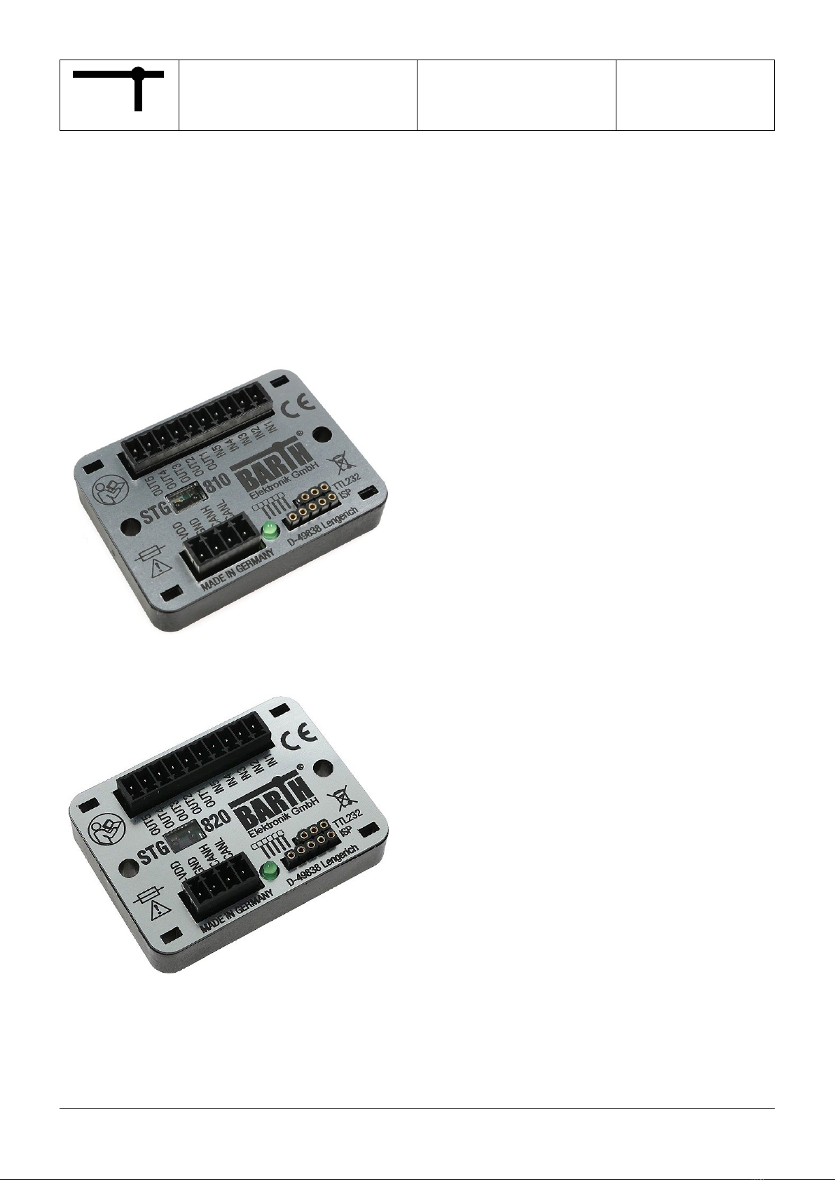
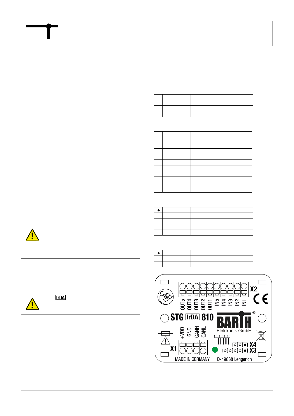
1 Product description
The picture below shows the BARTH®Mini-PLC STG-810
with the Connection Cable VK-16 (Art. No. 0019-0016).
The Mini-PLC is shipped without any Connection Cables.
1.1 Features
• Tiny and super-at CAN Logic Controller
• High-Performance 32 Bit ARM® Cortex®
• 3 analog Inputs 0 to 30 VDC, 12 bit ADC
• Event Counter Input 25 kHz
• Pulse and Frequency Counter Input 40µs
• 4 Solid-State Power Outputs up to 1.5 A
• 1 Power PWM Output 16 Bit 1 Hz to 25 kHz (STG-810)
• 1 analog Output 0 to 5V up to 100kHz (STG-820)
• CAN 2.0A/B and SAE J1939 Interface
• CANopen® Interface
• IrDA/SIR Interface
• TTL-232 3.3V Interface
• Comprehensive Fail Safe Functions
• Open Source ‚C‘ Programming
• Compatible with PG-65 Programmer
• Wide Operating Voltage Range 7 to 32 VDC
• Wide Operating Temp. Range -40 to +70°C
• Vibration resistant and rugged Sealing
• Engineered and manufactured in Germany
1.2 Applications
• Industrial / Building Automation
• Automotive and Maritime Technology
• Technical Education / University
1.3 General description
The tiny STG-810/820 extend the well established BARTH®
Mini-PLC series with their smallest models coming with a
powerful 32 bit ARM® Cortex® Core and IrDA interface.
As the top-of-the-range product the STG-810/820 feature
rugged CAN/CANopen® connectivity with Open Source ‚C‘
programming capability at lowest current consumption and
the well-known small form factor.
The 32 bit ARM® Cortex® core provides two high speed
event, pulse and frequency counter inputs and one 16 bit
PWM output (STG-810) or analog 0-5V output (STG-820)
combined with a precise internal voltage reference for the
12 bit analog inputs. The automotive-qualied CAN2.0A/B/
CANopen® interface is able to operate in noisy environment
and allows the user to connect a variety of network compo-
nents to the Mini-PLC.
BAR
H
Elektronik GmbH
®
3/11
9021-0020-A
12.04.2017
A
Page:
Document:
Date:
Revision:
Mini-PLC
STG-810/820
Art. No. 0850-0810/820
MANUAL
© 2016-2017 BARTH Elektronik GmbH | Im Depot 1-3 | D-49838 Lengerich | www.barth-elektronik.de
® BARTH is a registered trademark. All rights reserved. 9021-0020-A
The STG-810/820 can be easily interfaced using the PG-65
Programmer to upload and download user-specied
program parameters.
The Mini-PLCs do not need any peripheral components to
operate. Both inputs and outputs features highly integrated
and rugged protection circuits to operate the Mini-PLC in
really harsh environment.
These outstanding features open up a variety of application
elds in industrial, automotive and 12/24V battery-powered
applications.
The STG-810/820 are also available as customer-tailored
OEM version within 8 weeks.
1.4 Open source programming
The STG-810/820 can be programmed as Open Source
Mini-PLCs using the powerful KEIL® μVision® Software
Suite. For everyone who is familar with C-Programming this
outstanding feature opens up a variety of hardware-oriented
possibilities in a realtime environment with powerful debug-
ging options.
1.5 Delivery content
• BARTH®Mini-PLC STG-810/820
• 2x Connectors for Mini-PLC
• Open Source Templates (Download)
• Manuals and Sample Programs (Download)
2 Installation
2.1 Mounting
The Mini-PLC must be installed and wired
by a trained technician who knows and
complies with both the universally appli-
cable engineering rules and the regula-
tions and standards that apply in specic
cases.
Fastening the STG-810/820 follows using either the integ-
rated mounting holes for screws or the holes for cable ties.
The cable tie installation method is recommended for faste-
ning the Mini-PLC on wiring harness, tubes or other mecha-
nical parts.
The window of the Mini-PLC must
not be covered for proper and reliable
infrared communication.
Take care to meet the environmental conditions of the
Mini-PLC.
2.2 Wiring
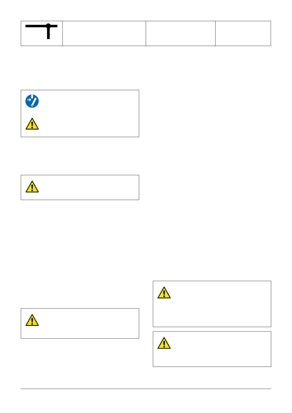
2.2.1 Overview
The graphic below shows the connection layout of the
BARTH®Mini-PLC STG-810/820.
X1 connector: power supply and CAN pins
1 +VDD positive supply terminal
2 GND ground terminal
3 CANH CAN high terminal
4 CANL CAN low terminal
X2 connector: inputs and outputs
1 IN1 analog / digital input
2 IN2 analog / digital input
3 IN3 analog / digital input
4 IN4 digital input / event counter
5 IN5 digital input / frequency counter
6 OUT1 highside output
7 OUT2 highside output
8 OUT3 highside output
9 OUT4 highside output
10 OUT5 STG-810: lowside output, PWM
STG-820: 0 to 5V analog output
X3 connector: Open Source ISP (via VK-35)
1 +3V3 positive power supply (Pin 1)
2 GND ground terminal
3 SYS_SWDIO system data IO
4 SYS_SWCLK system clock
5 SYS_RESETN system reset (inverted)
X4 connector: USB/232 interface (via VK-16)
1 GND ground terminal
2 TX 3V3 TTL TX terminal
3 RX 3V3 TTL RX terminal
BAR
H
Elektronik GmbH
®
4/11
9021-0020-A
12.04.2017
A
Page:
Document:
Date:
Revision:
Mini-PLC
STG-810/820
Art. No. 0850-0810/820
MANUAL
© 2016-2017 BARTH Elektronik GmbH | Im Depot 1-3 | D-49838 Lengerich | www.barth-elektronik.de
® BARTH is a registered trademark. All rights reserved. 9021-0020-A
2.2.4 Connecting the outputs
Depending on load type and current the Mini-PLC is able
to drive electric loads directly without any additional driver
or protection circuit. The Mini-PLC provides 4 digital solid-
state highside outputs and 1 solid-state lowside switch.
Features of OUT1 to OUT4
• Rugged solid-state higside switch up to 1.5A
• Switching up to 100Hz
• Paralleling permissible up to 4A
• Short circuit protection and current limitation
• Fast demagnetization of inductive loads
• Stable behaviour at undervoltage
• Comprehensive integrated protection circuits
• Outstanding electromagnetic compatibility (EMC)
• Electrostatic discharge protection (ESD)
Features of OUT5 (STG-810)
• Solid state lowside switch with PWM capability
• 16 bit PWM resolution from DC to 25kHz
• Sinks up to 2A
Features of OUT5 (STG-820)
• Analog 0 to 5VDC output
• Switches up to 100kHz
STG-810
The 10-pole connector X2 contains the digital outputs of
the Mini-PLC. While OUT1 to OUT4 are overload-protected
highside switches, OUT5 is carried out as lowside switch
with PWM capability without short circuit protection.
A logical HIGH within miCon-L will switch the Mini-PLS´s
supply voltage at OUT1 to OUT4, while OUT5 switches
lowside (GND). Aviod a sink current exceeding 2A at OUT5
because this outputs is not protected against short-circui-
ting or overload current !
STG-820
The 10-pole connector X2 contains the digital outputs of
the Mini-PLC. While OUT1 to OUT4 are overload-protected
highside switches, OUT5 is carried out as analog 0 to 5V
ouput with integrated short circuit protection (20mA).
The total current sourced by OUT1 to
OUT4 must not exceed 4A!
Avoid reverse voltage at any output higher
than the Mini-PLC´s supply voltage!
OUT5 provides NO short circuit protection.
Take care the sink current not exceeds 2A!
Negligence may cause irreversible
damage of the Mini-PLC!
If you use C-Programming take care of
not switching OUT1 to OUT4 higher than
100Hz (STG-810: 25kHz for OUT5)!
Rise and fall times of the output driver IC
will cause higher power-losses resulting
in heat dissipation.
Please refer to the appendix for detailed electrical
specication of the outputs.
2.2.2 Connecting the power supply
The STG-810/820 feature an outstanding wide supply
voltage range from 7 to 32 VDC at lowest current consump-
tion. So the Mini-PLCs can be integrated within battery
supplied 12V or 24V DC systems (cars, trucks, battery
powered cars, forklifts and digger, for example).
Turn off the power supply before perfor-
ming any wiring operations!
False electrical connection, voltage
reversal or disregarding the electrical
specications may cause irreversible
damage of the Mini-PLC!
Connect the supply voltage of 7 to 32 VDC to the 4-pole
terminal X1 of the Mini-PLC. Wire the positive supply to the
‚+VDD‘ marked connection. The negative (ground) will be
wired to the ‚GND‘ connection. All terminals are carried out
as plugable spring terminal connectors for a wire gauge of
0.25 to 1.5mm².
Ensure correct power supply voltage
range and polarisation! External fusing of
5A max. is mandatory! Disregarding may
cause irreversible damage of the PLC!
2.2.3 Connecting the inputs
You can connect sensors, switches or buttons to the inputs.
The sensors may be temperature, ow, pressure, photo-
electric sensors or proximity switches, for example.
Features of IN1 to IN5
• IN1 to IN3 are selectable analog/digital inputs
• IN4 is an digital or event counter input up to 25kHz
• IN5 is an digital or frequency counter input up to 25kHz
• Wide input voltage range 0 to 32VDC
• IN1 to IN3 are 0 to 10/30 V compatible (12 bit)
• Comprehensive integrated protection circuits
• Outstanding electromagnetic compatibility (EMC)
• Electrostatic discharge protection (ESD)
Due to the pull-down resistors integrated in the Mini-PLC
any switch (NO/NC) can simply be connected between the
positive supply (VDD) of the Mini-PLC and the desired input.
The voltage at any input must not exceed
32VDC referred to ground (GND).
Higher voltages or reverse voltage lower
than -32VDC may cause irreversible
damage of the Mini-PLC!
The 10-pole connector named X2 contains the inputs of
the Mini-PLC. While IN4 and IN5 are pure digital inputs, IN1
to IN3 provide both digital or analog (0-30V) functionality.
The voltage range for all inputs may not exceed 32 VDC. All
inputs refer to GND.
Please refer to the appendix for detailed electrical
specication of the inputs.
BAR
H
Elektronik GmbH
®
5/11
9021-0020-A
12.04.2017
A
Page:
Document:
Date:
Revision:
Mini-PLC
STG-810/820
Art. No. 0850-0810/820
MANUAL
© 2016-2017 BARTH Elektronik GmbH | Im Depot 1-3 | D-49838 Lengerich | www.barth-elektronik.de
® BARTH is a registered trademark. All rights reserved. 9021-0020-A
2.2.5 Connecting the CAN interface
The X1 connector of the Mini-PLC contains the CAN-
specic pins ‚CANH‘ and ‚CANL‘.
The voltage at CANH or CANL must not
exceed -32 or +32 VDC referred to ground
(GND). Higher voltages may cause irrever-
sible damage of the Mini-PLC!
There is no termination resistor (120R) integrated in the
Mini-PLC. Please add a 120R resistor at both ends (2) for
CAN bus termination.
2.2.6 Connecting the programming interface
Please use the X3 connector for programming and debug-
ging via the Connection Cable VK-35 (BARTH® Art. No.
0091-0035).
2.2.7 Using the IrDA interface
The STG-810/820 feature an IrDA (SIR) interface which
bases on infrared light technology to transfer serial data.
This interface can be used in combination with the BARTH®
PG-65 Parameter programmer (BARTH® Art. No. 0017-
0065) to communicate user-dened parameters.
Learn more about this feature in the PG-65 user manual and
product documentation.
3 Open source programming
The STG-810/820 will be programmed as Open Source
Mini-PLC using the powerful KEIL® μVision® Software
Suite. For everyone who is familar with C-Programming this
option opens up a variety of hardware-oriented features in
a realtime environment with powerful debugging features.
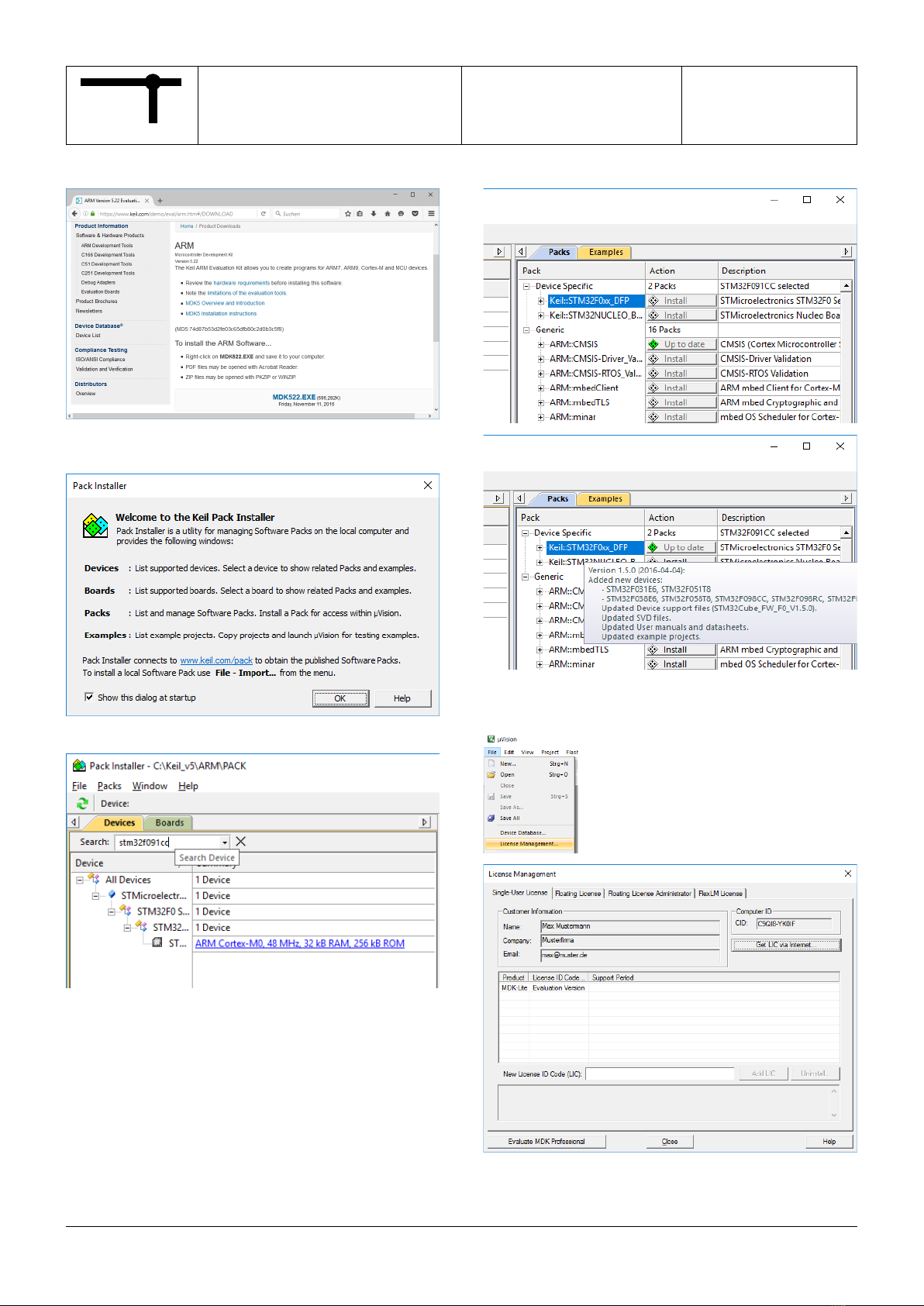
3.1 Software download
In the rst step please download the KEIL® μVision® Soft-
ware Suite from:
http://www2.keil.com/stmicroelectronics-stm32/mdk
The BARTH® STG-810 software package is available from:
http://www.barth-elektronik.de/download/9045-0015-A.zip
The BARTH® STG-820 software package is available from:
http://www.barth-elektronik.de/download/9045-0016-A.zip
The package includes free and ready-to-use sample
programming templates. Each template refers to the
STG-810/820´s hardware design and contains all required
port connections. To create your own project simply modify
or extend one of the following programming templates.
To get your password to unzipp the software package
please write the following lled mail template to:
ofce@barth-elektronik.de
First Name:
Surename:
Company:
City:
State:
Country:
STG-810/820 Serial Number:
Email Address:
Within 24h you will receive your individual password to
unzipp the the BARTH® software package.
Now rst install the KEIL® μVision® Software Suite:
BAR
H
Elektronik GmbH
®
6/11
9021-0020-A
12.04.2017
A
Page:
Document:
Date:
Revision:
Mini-PLC
STG-810/820
Art. No. 0850-0810/820
MANUAL
© 2016-2017 BARTH Elektronik GmbH | Im Depot 1-3 | D-49838 Lengerich | www.barth-elektronik.de
® BARTH is a registered trademark. All rights reserved. 9021-0020-A
Please follow the software setup instructions.
After successful software installation the Pack Installer will
be lauched:
Please search for the ‚STM32F091CC‘ device.
Select the device-specic packages to be installed.
Now please open the ‚License Management‘ to enable your
free KEIL® μVision® Software Suite.

BAR
H
Elektronik GmbH
®
7/11
9021-0020-A
12.04.2017
A
Page:
Document:
Date:
Revision:
Mini-PLC
STG-810/820
Art. No. 0850-0810/820
MANUAL
© 2016-2017 BARTH Elektronik GmbH | Im Depot 1-3 | D-49838 Lengerich | www.barth-elektronik.de
® BARTH is a registered trademark. All rights reserved. 9021-0020-A
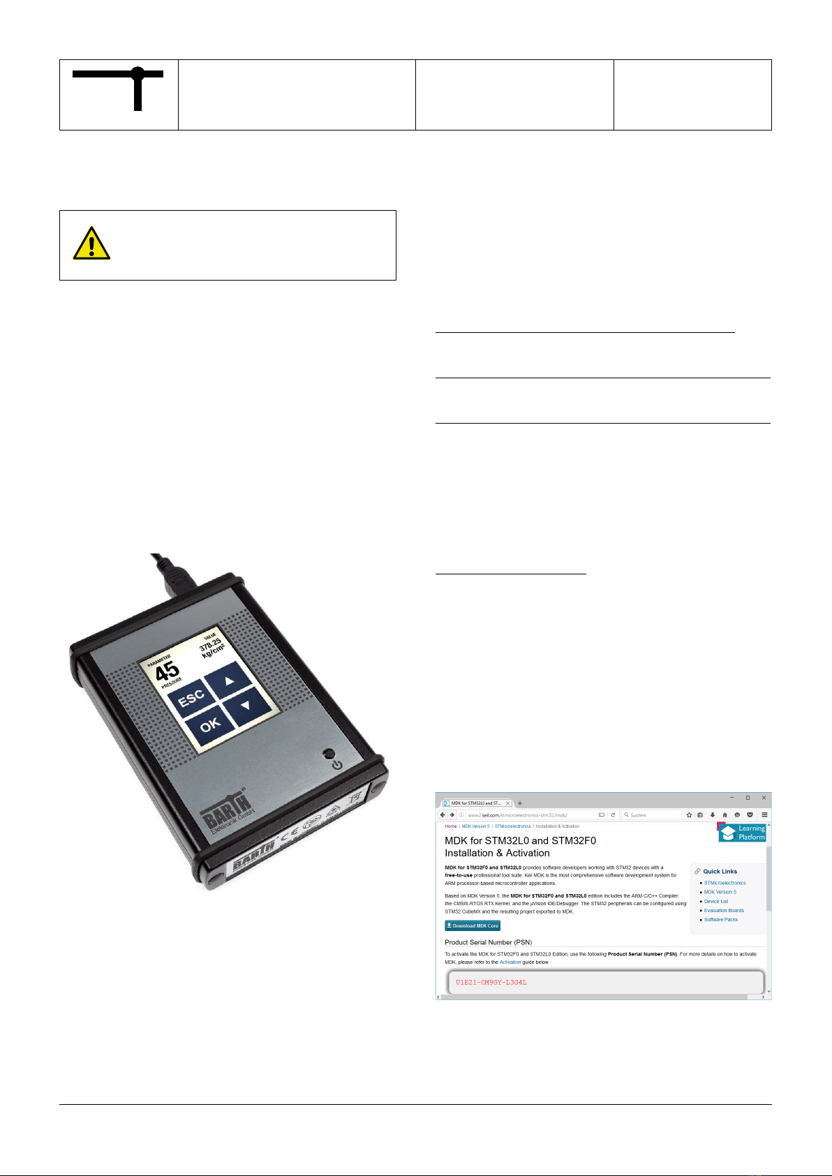
Add your personal Product Serial Number. To program and debug the Mini-PLC, the ST-Link/V2-Isol
Programmer is required (BARTH® Art. No. 0017-0066 and
Connection Cable VK-35 Art. No. 0091-0035).
Please download the ‚ST-LINK/V2‘ driver from:
http://www.st.com
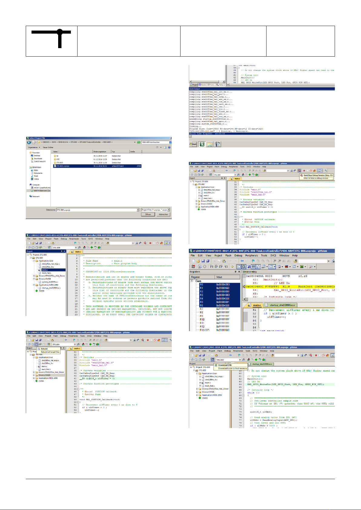
Now open a sample project in the KEIL® μVision® Software
Suite.
Open the ‚options‘ menu and select ‚ST-Link Debugger‘ as
your favourite programmer/debugger tool.

BAR
H
Elektronik GmbH
®
8/11
9021-0020-A
12.04.2017
A
Page:
Document:
Date:
Revision:
Mini-PLC
STG-810/820
Art. No. 0850-0810/820
MANUAL
© 2016-2017 BARTH Elektronik GmbH | Im Depot 1-3 | D-49838 Lengerich | www.barth-elektronik.de
® BARTH is a registered trademark. All rights reserved. 9021-0020-A
Please ensure the following programmer settings.
Now build and download a sample project.
After successful download you will be able to debug the
project.
To read online values you have to set the optimization level
down to ‚0‘ in the ‚C/C++ options menu‘.
3.2 Connecting the Mini-PLC
To program and debug the Mini-PLC, the ST-Link/V2-Isol
Programmer (BARTH® Art. No. 0017-0066 and the Connec-
tion Cable VK-35 Art. No. 0091-0035) are required.
To connect the programmer to the STG-810/820 please
use the X3 connector. The X4 connector can be used as
TTL232 UART interface within your application.
For USB communication please use the VK-16 Connection
Cable (BARTH® Art. No. 0091-0016).
BAR
H
Elektronik GmbH
®
9/11
9021-0020-A
12.04.2017
A
Page:
Document:
Date:
Revision:
Mini-PLC
STG-810/820
Art. No. 0850-0810/820
MANUAL
© 2016-2017 BARTH Elektronik GmbH | Im Depot 1-3 | D-49838 Lengerich | www.barth-elektronik.de
® BARTH is a registered trademark. All rights reserved. 9021-0020-A
3.3 First steps in KEIL® μVision®
The BARTH® software packages 9045-0015-A.zip (for
STG-810) and 9045-0016-A.zip (for STG-820) include
numerous free and ready-to-use sample programming
templates. Each template refers to the Mini-PLC´s hardware
design and contains all required port connections.
To create your own project simply modify or extend one of
the following programming templates.
Choose and open your favourite sample programming
template project in the KEIL® μVision® Software.
Open the ‚main.c‘ from the sample project.
Rebulid the project.
Wait... and have a look at the Output Window during the
Rebuild.
Now start your Debug Session...
5
...or download (F8) your application instead of debugging.
Now you are at the point to create your own programs.
Have fun with your BARTH®Mini-PLC !

BAR
H
Elektronik GmbH
®
10/11
9021-0020-A
12.04.2017
A
Page:
Document:
Date:
Revision:
Mini-PLC
STG-810/820
Art. No. 0850-0810/820
MANUAL
© 2016-2017 BARTH Elektronik GmbH | Im Depot 1-3 | D-49838 Lengerich | www.barth-elektronik.de
® BARTH is a registered trademark. All rights reserved. 9021-0020-A
4 Appendix
4.1 Specications
4.1.1 General
Hardware design BARTH®IrDA Mini-PLC
fully enclosed in proprietary PU
resin, tiny and rugged housing
with plugable spring terminal
connectors, ultra-lightweight
Programming options Open Source,
C-Programming using the
powerful KEIL®µVision® Software,
free license
Interfaces UART TTL232 (3.3V TTL level)
USB (VK-16 required)
reserved for miCon-L software
communication or USB/COM
CAN 2.0A/B/open®/SAE J1939
NMEA2000
IrDA/SIR
(for PG-65 communication)
4.1.2 Power supply
Operating voltage 7 to 32 VDC
Current consumption nominal 10 mA at 32 VDC
(depending on conguration)
Fusing 5 A max. (external)
mandatory for voltage reversal
protection
Voltage reversal protection yes
(combined with external fuse)
ESD/TVS protection yes, integrated
Heat dissipation air
(at full load)
normally < 2 W
4.1.3 Inputs
Number digital 2+3
Number analog 3
Analog / digital input
IN1 - IN3
UIN = 0 to 30 VDC
RIN > 11 kOhm
fIN <= 1kHz
tIN >= 1 ms
Digital / counter input
IN4 - IN5
UIN = 0..30 VDC
RIN > 20 kOhm
ULOW < 3 VDC
UHIGH > =5 VDC
fIN <= 25 kHz
tIN >= 40 µs
Accuracy ADC
IN1 - IN3
<0.15 VDC
ADC resolution
(internal)
12 Bit
Potential isolation no (common GND)
ESD/TVS protection yes
Permissible cable lenght
(per input)
normally 40 m
4.1.4 Outputs
Number digital 4+1
Number PWM 1
Output OUT1 - OUT4 Output type: solid state (highside)
IOUT <= 1.5 A (resistive load)
@ fOUT = 0 to 100 Hz
UOUT >= UIN-0,45 V
ITOT<= 4 A (paralleling permissible)
Maximal allowable load
inductance for a single switch off
(one output):
VDD=12VDC, IL=1.5A, ZL<=70mH
VDD=12VDC, IL=1A, ZL<=200mH
On-state resistance VDD to OUT:
RON<=180 mOhm
Turn-on time: tON<=250 µs
Turn-off time: tOFF<=270 µs
OUT5 (STG-810) Output type: solid state (lowside)
IOUT <= 2 A (resistive load)
@ fOUT = DC to 25 kHz
IOUT <= 1 A (inductive load)
OUT5 (STG-820) 0 to 5 VDC analog output
IOUT <= 20 mA (resistive load)
@ fOUT = DC to 100 kHz
Potential isolation no
4.1.5 Interfaces
CAN CAN 2.0A/B:
11/29 bit ID, base frame format
Baud rates:
50, 100, 125, 250, 500 kbit, 1Mbit
CANopen® multi line, single line,
master, slave
SAE J1939
NMEA 2000
Meets or exceeds the require-
ments of applications ISO
11898-2, loss of ground
protection from –32 V to +32 V,
thermal shutdown protection
TTL232 3.3V TTL level, cong: 8N1
Baud rates: 2400 to 115.2 kbit/s
IrDA (infrared) SIR (9.6 kbit/s to 115.2 kbit/s)
IrPHY (for PG-65 communication)
4.1.6 Security features
Security Features System and independent
watchdog
Fail safe oscillator
Power on/down reset
Supply voltage supervisor
4.1.7 Program and data memory
Memory 256 kB Flash program memory
32 kB SRAM
64 kB EEPROM

BAR
H
Elektronik GmbH
®
11/11
9021-0020-A
12.04.2017
A
Page:
Document:
Date:
Revision:
Mini-PLC
STG-810/820
Art. No. 0850-0810/820
MANUAL
© 2016-2017 BARTH Elektronik GmbH | Im Depot 1-3 | D-49838 Lengerich | www.barth-elektronik.de
® BARTH is a registered trademark. All rights reserved. 9021-0020-A
4.1.8 Timebase (oscillator)
Primary Oscillator Crystal quartz MEMS unit
(precise ‚micro-electro-mecha-
nical system‘)
Nominal Frequency 16.000 MHz
Frequency tolerance ±50 × 10-6
Frequency aging ±5 × 10⁻⁶ / year max.
4.1.9 Electrical connection
Electrical Connection plugable spring terminal
connectors 0.25 to 1.5 mm²
Manufacturer: Phoenix Contact
Series: COMBICON
Type: FMC1,5/x-ST-3,5-BK
4.1.10 Electromagnetic compatibility (EMC)
Electrostatic discharge
(ESD) on IN1 to IN5
20 kV air discharge
30 kV contact discharge
(IEC/EN 61 000-4-2, level 3)
Electrostatic discharge
(ESD) on OUT1 to OUT5
8 kV (human body model)
(MIL-STD883D)
Electromagnetic elds Field strength 10 V/m
(IEC/EN 61000-4-3)
CAN bus terminals
(CANH, CANL to GND)
IEC 61000-4-2:
Unpowered Contact Discharge
±15000 V
IEC 61000-4-2:
Powered Contact Discharge
±8000 V
4.1.11 Environmental conditions
Operation temperature -40 to +70 °C
(IEC 60068-2-1/2)
Storage temperature -40 to +70 °C
(IEC 60068-2-1/2)
Relative humidity 5 to 95% non-condensing
(IEC 60068-2-30)
Air pressure (in operation) 500 to 1500 hPa
Shock resistance min. 100 m/s²
(IEC 60068-2-27)
Vibration resistance min. 50 m/s² @ 10..100 Hz
(IEC 60068-2-6)
Degree of protection IP 20, limited by connectors
(EN 50178, IEC 60529)
Drop Drop height: 1000 mm
(IEC 60068-2-31)
Free fall (packaged) 1500 mm
(IEC 60068-2-32)
4.1.12 Weight and dimensions
Weight 50 g
(without connectors)
Dimensions 60 x 45 x 15 mm (LxWxH)
Mounting via two M4 screws or 3.6mm
cable ties
4.1.13 Ordering information
Ordering information
Mini-PLC
Mini-PLC STG-810
Art. No. 0850-0810
GTIN 4251329401320
Mini-PLC STG-820
Art. No. 0850-0820
GTIN 4251329401382
Ordering information
accessory
Connection Cable VK-16
(TTL232 <-> USB)
Art. No. 0091-0016
GTIN 4251329400187
Connection Cable VK-35 (OS)
Art. No. 0091-0035
GTIN 4251329401276
Programmer ST-Link/V2 ISOL
Art. No. 0017-0066
GTIN 4251329401269
4.2 Documents, videos and software
Detailed information, additional documents, application
notes and videos relating to this product are downloadable
from www.barth-elektronik.de and www.micon-l.de
4.3 Disposal
If you wish to nally dispose of the
product, ask your local recycling centre
or dealer for details about how to do
this in accordance with the applicable
disposal regulations.
4.4 Conformity declaration
For the following designated product it is hereby conrmed,
that the construction in that technical design brought by us
in trafc corresponds to the standards specied below. In
the event of any alternation which has not been approved
by us being made to any device as designated below, this
statement shall thereby be made invalid.
Description Mini-PLC
Type STG-810/820
Art. No. 0850-0810/820
Directive
2004/108/EG relating to-
electromagnetic
compatibility (EMC)
Applied norms:
2004/108/EG
2004/108/EC
2014/30/EU
RoHS Directive
2011/65EU
We herby declare that our
product is compilant to the RoHS
Directive on restriction of the use
of certain hazardous substances
in electrical and electronic appli-
ances.
BARTH®Elektronik GmbH, Lengerich, 03.10.2016
Dipl.-Ing. (FH) D. Barth, Managing Director
This manual suits for next models
1
Table of contents
Other Barth Control Unit manuals

Popular Control Unit manuals by other brands

PHOTOWATT
PHOTOWATT PW1650 user guide

Lutron Electronics
Lutron Electronics PowPak RMJS-CCO1-24-B Installation

Festo
Festo CPX-E Instructions for use

Johnson Controls
Johnson Controls tyco AMD-1 manual

Emerson
Emerson Sapag 1100 Installation and maintenance instructions

Speakman
Speakman SEF-TW Installation, Maintenance & Operation Instructions

Carlisle
Carlisle BINKS 240-2012-AC Service manual

Spectrum Controls
Spectrum Controls SLC 500 user manual

ICP DAS USA
ICP DAS USA ET-7000 series quick start

AXIOMTEK
AXIOMTEK FAB209-3B1 Quick installation guide

Honeywell
Honeywell SmartPAC 2 user manual

ARI
ARI Eliptix R-30ME Installation, Operating, Maintenance


