Barudan BEXS User manual

B E X S
Instruction Manual

Table of Contents
Chapter 1 Safety Instructions ............................................. 1‐ 1
1.Important Safety Instructions .................................................... 1‐ 2
2.Grounding Instructions ............................................................... 1‐ 5
3.Warning Labels ........................................................................... 1‐ 6
Chapter 2 Introduction ...................................................... 2‐ 1
1.Specification ................................................................................. 2‐ 2
2.Features ....................................................................................... 2‐ 3
Chapter 3 Before Use ......................................................... 3‐ 1
1.Appearance and Components ..................................................... 3‐ 2
2.Panel Switches ............................................................................ 3‐ 6
3.Powering the Machine On / Off .................................................. 3‐ 8
4.Origin Set ..................................................................................... 3‐ 9
5.Screen Structure .......................................................................... 3‐10
6.Information Screen ...................................................................... 3‐11
7.Design List Display Settings ...................................................... 3‐13
8.Stand-By and Drive Mode ........................................................... 3‐15
9.Switching Screens ....................................................................... 3‐16
10.Numeric Entry Dialogue Box ...................................................... 3‐18
11.Character Entry Dialogue Box ................................................... 3‐19
12.Confirmation Message ................................................................ 3‐20
13.Error Messages ............................................................................ 3‐21
Chapter 4 Manual Operations ............................................. 4‐ 1
1.Color (Needle) Change ................................................................ 4‐ 2

2.Presser Foot Height Adjustment ................................................ 4‐ 4
3.Trimmer ....................................................................................... 4‐ 5
4.Thread Clamp .............................................................................. 4‐ 7
5.Appliqué ....................................................................................... 4‐ 8
6.Change Frame ............................................................................. 4‐ 9
7.Bobbin Counter ............................................................................ 4‐10
8.Main Motor Brake ....................................................................... 4‐12
9.Lubrication (Machine Maintenance) .......................................... 4‐13
10.Holding the Needle at the Dead Bottom Center ........................ 4‐19
11.Manual Roll-to-Roll Feature ....................................................... 4‐20
12.Laser Pointer ............................................................................... 4‐22
Chapter 5 Loading / Saving Designs .................................... 5‐ 1
1.Before Loading / Downloading Designs ...................................... 5‐ 2
2.Before Using a USB Flash Drive ................................................ 5‐ 4
3.Loading Designs from a USB Flash Drive ................................. 5‐ 7
4.Saving Designs to a USB Flash Drive ........................................ 5‐12
5.USB Administration .................................................................... 5‐15
6.ABC Drive .................................................................................... 5‐20
7.Loading Thorough the COM port ............................................... 5‐21
8.Saving Through the COM port ................................................... 5‐24
Chapter 6 Memory Designs ................................................ 6‐ 1
1.Selecting a Design ....................................................................... 6‐ 2
2.Design Information ..................................................................... 6‐ 3
3.Changing Design Names ............................................................. 6‐ 5
4.Production Counts ....................................................................... 6‐ 6
5.Deleting Designs from Memory .................................................. 6‐ 8
6.Changing Color Codes of a Design ............................................. 6‐ 9

7.Outline Stitching ......................................................................... 6‐13
8.Thread Consumption ................................................................... 6‐15
Chapter 7 Programs .......................................................... 7‐ 1
1.Changing Program Settings ....................................................... 7‐ 2
2.Program List ................................................................................ 7‐ 4
3.Setting the Sub-Soft Limit .......................................................... 7‐ 7
4.Matrix Embroidery Set Up (Design Repeats) ............................ 7‐ 9
5.Automatic Matrix Embroidery Set Up ....................................... 7‐11
Chapter 8 Embroidery ....................................................... 8‐ 1
1.Start Point ................................................................................... 8‐ 2
2.Drive Mode ................................................................................... 8‐ 3
3.Speed ............................................................................................ 8‐ 4
4.Trace ............................................................................................ 8‐ 5
5.Float ............................................................................................. 8‐ 7
6.High Speed Float (By Stitch Count) ........................................... 8‐ 8
7.High Speed Float (By Color Change) ......................................... 8‐ 9
8.Color Code Change (Teaching) ................................................... 8‐10
9.Function Codes ............................................................................ 8‐11
10.Stitch Back .................................................................................. 8‐12
11.Automending ............................................................................... 8‐13
12.Stand-By Mode (Resume) ........................................................... 8‐14
Chapter 9 Network ............................................................ 9‐ 1
1.Before Using the Network System ............................................. 9‐ 2
2.Registering the Operator Code ................................................... 9‐ 4
3.Break Call .................................................................................... 9‐ 6
4.Operator Call ............................................................................... 9‐ 7

5.Time-Out ...................................................................................... 9‐ 8
6.Downloading Designs (Direct Downloading) ............................. 9‐ 9
7.Downloading Designs (Schedule Downloading) ......................... 9‐12
Chapter 10 Editing Memory Designs ................................. 10‐ 1
1.Color Change Function Codes ................................................. 10‐ 2
2.All Function Codes ................................................................... 10‐ 3
3.Running Stitch Additions ........................................................ 10‐ 4
4.DSP (Design Stitch Processor) ................................................. 10‐ 6
Chapter 11 Preference ..................................................... 11‐ 1
1.Changing Machine Conditions (MC) ....................................... 11‐ 2
2.MC List ..................................................................................... 11‐ 4
3.Sequin Adjusting Mode ............................................................ 11‐13
4.Setting the Screen Color .......................................................... 11‐14
5.Setting the Design Color .......................................................... 11‐17
6.Network .................................................................................... 11‐20
7.Date Setting .............................................................................. 11‐22
8.Software Version ...................................................................... 11‐23
Chapter 12 System .......................................................... 12‐ 1
1.System Structuring .................................................................. 12‐ 2
2.System Software Update ......................................................... 12‐ 3
3.Initializing Memory .................................................................. 12‐ 5
Chapter 13 Appendix ....................................................... 13‐ 1
1.Function Codes ......................................................................... 13‐ 2
2.Sub-Function Codes ................................................................. 13‐ 3
3.Error Messages ......................................................................... 13‐ 4

1‐1
Chapter 1. Safety Instructions
This chapter contains information on the following.
1. Important Safety Instructions
2. Grounding Instructions
3. Warning Labels

1‐2
1. Important Safety Instructions
■ Before using the machine, make sure to read this manual thoroughly and follow all
instructions.
■ The icons in the manual show the importance of the contents.
Acknowledge the following descriptions beforehand.
Icons
!Warning
!Caution
Safety information about protecting yourself.
Safety information about protecting the machine.

1‐3
!Caution
◆This machine is made for an industrial use.
This is an embroidery machine. Do not use for other applications.
◆ Read the instruction manual thoroughly and acknowledge the operation before running the
machine.
◆ Only those that know how to operate the machine should run the machine. Do not let other
personnel operate the machine.
◆Operate the machine from the front. Do not load work to the machine from the backside.
◆ Keep hands and face away from needles, take-up lever, trimmer, shafts, pulley, belts, gears,
etc. Do not operate the machine without the protect covers for the shaft, pulley belt and fear
in place.
◆Keep long hair, necklaces, and bracelets away from the machine while operating.
◆ Only one person should operate the machine. Having a multiple operators for one machine
may be dangerous as one operator may start t the machine while another is working on it.
◆ Before starting the machine, be sure nobody is near the machine.
◆ Keep children away from the machine while operating.
◆Follow the electrical specifications instructed.
◆Do not modify or dismantle the machine. It can cause fire or malfunction.
◆Connect this embroidery machine to a properly grounded outlet only.
◆Do not use the machine in the humid area. It can cause a fire or electrical shock.
◆ Do not damage, modify, pull or twist the power cable. Heating or heavy load to the cable
damages the cable and it can cause fire or electrical shock.
! Warning
◆Keep water or chemical substances away from the controller.
In case it happened, disconnect the power from the machine and call a service technician.
◆ Keep any metal items such as clips, safety pins scissors etc away from the controller to avoid
a short to the circuit, fire or electrical shock.
◆ Keep vases, flowerpots, cups, cosmetics, medicine, and chemical substances away from the
controller. They could cause fire or electric shocks.
◆ Disconnect the power to the machine and call a service technician if any foreign objects go
into the controller.

1‐4
! Caution Adjustment of the machine
◆Stop the machine before threading the machine or checking the embroidery in process.
◆Disconnect the power to the machine before turning any shafts by hand.
◆ Disconnect the power to the machine or turn OFF the machine power before opening the
controller.
! Caution
◆Avoid direct sunlight, heaters, boilers or any sources of the heat from the machine.
Do not use the machine outdoors.
◆Do not use the machine near the fire of flame. It may cause fire.
◆ Clean the ventilation opening once a week.
Never operate the machine with any air openings blocked. Keep ventilation openings of the
machine free from the accumulation of lint, dust, and loose cloth.
◆ Unplug the power cable before servicing to the controller. Residual power may cause electric
shock. Wait for more than 4 minutes before opening the cover.
Some parts in the controller can be very hot. Be sure not to burn your hands.
◆Use only attachment and parts recommended by Barudan.
Wrong parts can damage the machine.
◆Do not use bent or wrong sized needles.
It can make a needle break or fabric damaged.
◆Do not force the fabric while sewing. It can cause the needle to break or bend.
◆Turn off all power switches and unplug the power cable after use.
*Follow the lubrication instruction on the machine.

1‐5
2. Grounding instructions
1. Apply grounding to the machine.
Grounding avoids electric shocks.
Power cable on the machine has plug with a grounding terminal. Use appropriate plugs or
outlet which conform to the requirements of the power company or the law.
Danger! : Not grounding the machine may cause electrical shock.
2. Ask for a service call if the power connection is not clearly understood.
3. Do not use adaptor to the power plug.
Ask for a service call to connect the machine to another power source.
4. Ask for a service from the power company to check the connection from the ground to the
power outlet.
*Check the voltage and capacity of the power source before plugging the power cable.

1‐6
3. Warning labels
■ Give attention during operation to the parts labeled.
Warning Labels Contents
Needle Hazard Warning Label
Hair Warning Label
Take-Up Lever Warning Label
Frame Warning Label

1‐7
Warning Labels Contents
Hook Warning Label
Belt Warning Label

2‐1
Chapter 2 Introduction
This chapter contains information on the following.
1. Specifications
2. Features

2‐2
1. Specification
1. Design Capacity 100 designs
2. Stitch Capacity 1 design-1million stitches / Total capacity: 10 million stitches
3. Display 8.4 inch Color LCD 640 x 480 dots (VGA)
4. Temperature 5 – 45 Degree Centigrade (Active)
-20 – 60 Degree Centigrade (Storage)
5. Humidity 20 – 80 % RH, No condensation allowed
6. Grounding Grounding resistance to be less than 100Ohm (Type 3 grounding)
7. Trimmer Compatible Mark 4, 5, 6
8. Thread Break Detection
9. USB Ports USB2.0 (Front: 1 port Back: 2 ports)
10.Network system 100BASE / 10BASE
11.Emergency Stop Switch (Some models do not apply)
12.Option Cap frames (For Cylinder machines), Sequin device, Automatic
Lubrication system, Twin Sequin device, Light Curtain,
Automatic Presser Foot Height Adjuster, Barcode, Laser Marker,
Borer

2‐3
2. Features
1. Easy Operation
The XS Automat is specially designed for Barudan embroidery machines. Linux is used for the
OS, which allows high quality display and operation system. Graphic User Interface uses icons
that are easily recognized for quicker learning of operations.
2. USB
X Series Automat has USB ports. This enables the use of USB memory stick devices and the
following optional devices.
-Memory card reader -Barcode scanner
-Keyboard -Floppy Disk Drive
3. Standardized Networking Function
Barudan Embroidery machines can be connected to a Network server (computer) by LAN
connection and able to send / receive embroidery design data.
Moreover, by using the optional Network software, LEM Server, machine production records
and status can be viewed and reported from the server computer.
4. Large Memory Capacity
The memory capacity is 10 million stitches, with 100 memory locations.
5. High Speed Drive
The microcomputer automatically chooses the most efficient speed, in 10 rpm increments
*Max. Speed may vary for each model.
6. Quiet Drive
Inverter driven main motor allows powerful and quiet drive.
It also allows accurate speed control and stop positioning.
AC Servo Motor or 5 Phase Pulse Motor drives the pantograph at high speed and at the same
time, quietly.
7. Automatic speed and Jump stitch control
The controller varies the speed of the machine automatically depending on stitch length for
better stitch quality. The controller can also automatically convert long stitches to Jump
stitches as set by a stitch length parameter for higher quality stitching.
8. Design Information
Design information such as total stitch, quantity produced, size, and thumbnail of the design
can be seen on the screen.

2‐4
9. Head Selection System
Sewing Head switches can be turned On/Off individually depending on Design data.
They can also be switched On/Off by programming on the Automat.
10.Stitch Length Adjuster
Swing parameter allows satin stitches to be automatically sewn slightly wider or narrower
depending on the setting. This feature is helpful sewing small lettering when they need to be
sewn with a bolder effect.
11.Automatic Appliqué Positioning
This feature moves the pantograph out to a programmed position, when the machine stops for
an appliqué to be applied. This allows the operator to easily apply the appliqués to the
garments. This can also be used for replacing frames at the end of sewing.
12.Socks
Automatic design conversion for socks.
13.Matrix Embroidery
Automatic layout for the Matrix embroidery.
Easy setting can create a repetition design.
14.The registration of the start position
The controller automatically saves the last start position of designs in memory. When you go to
sew a design a second time, you can start from this same position.
15.Trace
The controller can show the area to be sewn on the screen and by a four-point trace and outline
trace.
16.Stand-By (Resume)
The machine can be turned OFF in the middle of a design. When powered back On, the
machine resumes in the same position where the embroidery was stopped, even if the
pantograph was moved when the machine was powered off.

3‐1
Chapter 3 Before Use
This chapter contains information on the following.
1. Appearance and Components
2. Panel Switches
3. Powering the Machine On / Off
4. Origin Set
5. Screen Structure
6. Information Screen
7. Design List Display Settings
8. Stand-By and Drive Mode
9. Switching Screens
10. Numeric Entry Dialogue Box
11. Character Entry Dialogue Box
12. Confirmation Message
13. Error Messages

3‐2
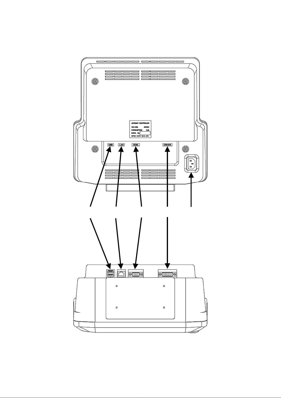
1. Appearance and Components
②
①
⑤
③
④
⑦
⑥
⑨
⑧
⑩
3‐3
⑪
⑭
⑮⑫
⑬

3‐4
1. LCD Display
Shows machine status, icons, and design information.
2. Icon key – A, B, C, D, E, F, and G-keys
Operation buttons assigned to functions displayed on screen above by icons.
3. Page key
Switches display screens. *Refer to
9. Switching Screens
.
4. Shift Key
Switches screen for more function options
5. Origin LED
When lit, the pantograph is located at the origin.
Blinks when the Jog Keys are assigned to other functions.
6. Origin key
Moves the Pantograph to the origin.
When the pantograph is located at origin, it moves the pantograph to the previous position, the
position of the last stitch while the machine was in Drive mode.
7. Jog Keys
Moves the Pantograph. Single stroke gives 0.1mm movement. Holding the button gives
continuous movement and the speed of the pantograph gradually increases. It is also used to
move the cursor for selecting items from a list.
8. Panel Keys
All operations start from selecting one of the Panel Keys.
When entering a number, these keys become a numeric key pad.
*Refer to
2. Panel Switches
for more details.
9. Power ON/OFF Keys
Turns the machine ON and OFF.
Table of contents
Other Barudan Industrial Equipment manuals

Popular Industrial Equipment manuals by other brands


Jorc
Jorc NUFORS-CR Maintenance instructions

Balluff
Balluff BCS Q40BBAA-PIM20C-EP-GS04 Series Configuration guide

Dover
Dover OPW 788 Series quick start guide

Graco
Graco ProMix PD2K Operation

MDS
MDS Ultra-Grip Attachable Grapple Mounting... Owner's/operator's manual

Salda
Salda AVS Series Mounting and installation instructions