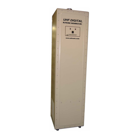
Altronic OMEGALINE 6600 Series User manual

ALTRONIC RESEARCH, INC.
P.O. BOX 249, YELLVILLE, ARKANSAS, U.S.A. 72687-0249
PHONE 870-449-4093 FAX 870-449-6000
1-800-482-LOAD (5623) in US
altronic.com
MODEL 6600 SERIES
COAXIAL LOAD RESISTOR

6600/Rev/Mar.2021 Page 2 Altronic Research Inc.
MODEL 6600 SERIES
RF COAXIAL LOADS
6606
6612 with
FANS
6620

6600/Rev/Mar.2021 Page 3 Altronic Research Inc.
ALTRONIC RESEARCH, INC.
P.O. BOX 249
YELLVILLE, ARKANSAS 72687, U.S.A.
DECLARATION OF CONFORMITY
The Omegaline RF Coaxial Load Model 6600 Series conforms to the following standards:
Low-Voltage Directive (2014/35/EU)
Electromagnetic Compatibility Directive (2014/30/EU)
Machinery Directive (2009/127/EC)
Restriction of Hazardous Substances Directive (EU)2015/863
Safety Requirements for Radio Transmitting Equipment
(IEC 215 / EN 60215)
As of the date of manufacture on the specifications page.
ATTEST:
John L. Dyess,
President

6600/Rev/Mar.2021 Page 4 Altronic Research Inc.
LIMITED WARRANTY
We take pride in manufacturing products of the highest quality and we warrant them to the
original purchaser to be free from defects in material and workmanship for the period of one year
from date of invoice. Additionally, products of our manufacture repaired by us are warranted
against defects in material and workmanship for a period of 90 days from date of invoice, with
the provisions described herein.
Should a product or a portion of a product of our manufacture prove faulty, in material or
workmanship, during the life of this warranty, we hereby obligate ourselves, at our own
discretion, to repair or replace such portions of the product as required to remedy such defect. If,
in our judgment, such repair or replacement fails to be a satisfactory solution, our limit of
obligation shall be no more than full refund of the purchase price.
This warranty is limited to products of our own manufacture. Equipment and components
originating from other manufacturers are warranted only to the limits of that manufacturer's
warranty to us. Furthermore, we shall not be liable for any injury, loss or damage, direct or
consequential, arising out of the use, or misuse (by operation above rated capacities, repairs not
made by us, or any misapplication) of the equipment. Before using, the user shall determine the
suitability of the product for the intended use; and the user assumes all risk and liability
whatsoever in connection therewith.
The foregoing is the only warranty of Altronic Research Incorporated and is in lieu of all other
warranties expressed or implied.
Warranty returns shall first be authorized by the Customer Service Department and shall be
shipped prepaid. Warranty does not cover freight charges.

6600/Rev/Mar.2021 Page 5 Altronic Research Inc.
TABLE OF CONTENTS
MODEL 6600 SERIES LOADS
SECTION PAGE
Declaration of Conformity..................................................................................3
Warranty .............................................................................................................4
Warnings and Precautions .............................................................................. 7-8
Introduction.........................................................................................................9
I. Description and Leading Particulars
1-1 Purpose and Application of Equipment........................................9
1-2 Equipment Supplied .....................................................................9
1-3 Equipment Required But Not Supplied........................................9
1-4 General Description......................................................................9
1-5 Mechanical Description................................................................9
1-6 General Principle of Operation............................................... 9-10
1-7 Operating and Adjustment Controls...........................................10
1-8 Electrical Description.................................................................10
1-9 Operator Training.......................................................................10
II. Test Equipment and Special Tools
2-1 Test Equipment Required...........................................................11
2-2 Special Tools Required...............................................................11
III. Preparation for Use and Reshipment
3-1 Unpacking Equipment................................................................11
3-2 Pre-Installation Inspection..........................................................11
3-3 Adding Fans................................................................................12
3-4 Pre-installation Test....................................................................13
3-5 Installation..................................................................................13
3-6 Location......................................................................................13
3-7 Mounting ....................................................................................13
3-8 Connections................................................................................13
3-9 Adjustments................................................................................13
3-10 Preparation for Reshipment.......................................................13
IV. Theory of Operation
4-1 General .......................................................................................14
V. Maintenance
5-1 Cleaning......................................................................................14
5-2 RF Circuit...................................................................................14
5-3 Resistor Replacement........................................................... 15-17

6600/Rev/Mar.2021 Page 6 Altronic Research Inc.
SECTION PAGE
VI. Diagrams
6-1 Outline and Dimensions ....................................................... 18-21
6-2 Parts List.....................................................................................22
VII. Specifications...........................................................................................23
VIII. Preservation and Corrosion Prevention Techniques.......................... 24-28

6600/Rev/Mar.2021 Page 7 Altronic Research Inc.
OPERATING TEMPERATURE
WARNING
FOR 6600 SERIES UNITS WITH FANS
CARE SHOULD BE TAKEN TO OPERATE UNIT BELOW STATED
MAXIMUM AMBIENT OPERATING TEMPERATURE.
OPERATION ABOVE RATED AMBIENT
TEMPERATURE CAN CAUSE MOTOR THERMAL
PROTECTION TO SHUT OFF FAN, WHICH WILL
CAUSE DAMAGE TO UNIT.
PROVISIONS ARE MADE TO TRIP THE INTERLOCK
IN THE EVENT OF OVERHEAT, BUT THE INTERLOCK
MUST BE PROPERLY CONNECTED TO THE RF SOURCE
FOR THIS FUNCTION TO OPERATE.
NEVER OPERATE WITH INTERLOCK
BYPASSED OR MALFUNCTIONING.
TO DO SO WILL VOID THE WARRANTY.

6600/Rev/Mar.2021 Page 8 Altronic Research Inc.
PRECAUTIONS
DANGER
Do not attempt any service or parts replacement without first disconnecting all
RF power. Failure to do so may result in serious or fatal electrical shock.
WARNING
The thermal alarm switch indicates an overtemperature condition of the load and
is not to be used for VSWR fault or transmitter protection.
WARNING
Digital Reject Load Warning: In a condition of load failure or if the load is
disconnected while the analog transmitter is operating, all coupled power is
directed to the digital transmitter. This will result in excessive reflected power
and immediate destruction of the digital transmitter if automatic VSWR
protection is not in effect.
OPERATING TEMPERATURE WARNING
Care should be taken to operate unit below stated maximum ambient operating
temperature. OPERATION ABOVE RATED AMBIENT TEMPERATURE
MAY CAUSE DAMAGE TO UNIT.
CAUTION
Hazardous temperatures within this device ma
y
i
g
nite combustible materials.
Place device on non-combustible pad and keep grass and other combustibles
clear. Maintain free airflow around load at all times. Do not block air grills;
blocking air flow can cause unit to fail!
CAUTION
Do not apply more than rated power to unit.
Damage will occur if large overloads are applied.
1CAUTION1
When using any cleaning solvents or solutions, assure that there is adequate
ventilation to protect personnel from breathing any irritable or possibly toxic
fumes.

6600/Rev/Mar.2021 Page 9 Altronic Research Inc.
INTRODUCTION
This handbook was prepared for skilled personnel as an aid in understanding and performing
installation, service and maintenance procedures for the OMEGALINE Model 6600 Series
Coaxial Load. Personnel are considered to be skilled if they have the necessary knowledge and
practical experience of electrical and radio engineering to appreciate the various hazards that can
arise from working on radio transmitters, and to take appropriate precautions to ensure the safety
of personnel.
SECTION I
DESCRIPTION AND LEADING PARTICULARS
1-1. Purpose and Application of Equipment. The OMEGALINE Model 6600 Series Coaxial
Loads are designed to safely dissipate 6,000, 12,000, and 20,000 watts maximum of
electrical energy over a frequency range of DC to 110 MHz.
1-2. Equipment Supplied. The Model 6600 Series Coaxial Load is supplied with standard RF
connectors. Their designations are:
1-5/8" EIA Swivel flange: Model # 6600E1
1-5/8" Unflanged flush: Model # 6600F1
1-5/8" Unflanged recessed: Model # 6600R1
3-1/8” EIA Swivel flange: Model # 6600E3
Units purchased with fans have three terminal connections supplied for AC main power.
1-3. Equipment Required But Not Supplied. The Model 6600 Series Coaxial Load is
complete as supplied, but the user must furnish RF input, and alarm indicator cable. For
units purchased with fans the user must also supply interlock control cable, AC main power
and ground cable appropriate for each installation. A user supplied disconnect must be in
place before operating this load.
1-4. General Description. The Model 6600 Series Coaxial Load is enclosed in a single
aluminum case which is painted with a durable acrylic finish. The RF connector is located
on the end panel of the load .
1-5. Mechanical Description. The Model 6600 Series RF Coaxial Load is a 50 ohm non-
reactive resistor assembly which is cooled by ambient air. Units purchased with fans are
cooled by air forced through the resistor assembly by two 12-inch fans.
1-6. General Principle of Operation. After ascertaining that the Model 6600 Series Coaxial
Load is correctly connected to the RF source and the transmitter alarm, operate transmitter
as desired. Units purchased with fans may be operated after ascertaining that the load is
connected to the correct power supply with a disconnect, connect the transmitter interlock

6600/Rev/Mar.2021 Page 10 Altronic Research Inc.
circuit, the alarm circuit, and RF source(s). Turn the user supplied main power switch
"ON" and enable the transmitter. Operate the transmitter as desired. To stop operation, it
is necessary to first turn off the transmitter. The fan may continue to run for some time.
This depends upon the power level at which the load was operating and upon the ambient
air temperature. This feature is necessary to prevent damage to the load. 6600 Series
Coaxial Loads with fans operates in "Standby" or "Reject" mode with the blower off.
1-7. Operating and Adjustment Controls. No field adjustments are necessary or possible.
1-8. Electrical Description. Models sold with fans contains a 50-ohm non-reactive resistor
assembly capable of dissipating a total of their rated watts of applied electrical energy at
frequencies between DC and 110MHz with a maximum VSWR of 1.10 to 1. No provisions
are made for tuning the resistor assembly and all operating controls relate to the operation
of the optional fan assembly. The fan control circuit consists of two switches wired in
parallel to control the fan motor. Power is supplied to the fan whenever the equipment is
attached to the correct power supply and the user supplied main power switch is "ON" and
the fan thermal switch senses a temperature equal to or greater than 120°(±7 °)F. When
sold with fans the transmitter interlock circuit consists of one normally closed 250°F
thermal switch wired to terminals (C,D) on the Amphenol four pin cylindrical twist lock
connector located on the front panel of the unit. There is no interlock circuit provided for
units sold without fans. The alarm circuit consists of one normally closed 372°F thermal
switch wired to terminals (A,B) on the Amphenol four pin cylindrical twist lock connector.
1-9. Operator Training. The operator of this equipment must have the following
skills/knowledge:
An understanding of the purpose of the equipment;
An understanding of the principles of operation of the equipment;
An understanding of the normal operating procedures for the equipment;
An understanding of the normal and abnormal indications which may be presented at
the control point;
The proper procedures for starting, using and stopping the equipment under normal
conditions;
The proper procedure for stopping the equipment under abnormal or emergency
conditions;
The proper procedure to lock out and mark controls prior to allowing or commencing
maintenance on the equipment;
The proper procedure to obtain clearance to remove lockouts and out-of-service
marks and return the equipment to normal service.

6600/Rev/Mar.2021 Page 11 Altronic Research Inc.
SECTION II
TEST EQUIPMENT AND SPECIAL TOOLS
2-1. Test Equipment Required. No test equipment is required for routine maintenance. In
some circumstances it may be desirable to determine the temperature differential (outlet air
minus inlet air) and ambient air temperature which the equipment is experiencing. We
recommend the John B. Fluke Mfg. Co. Model 52 or equivalent instrument for this
function.
2-2. Special Tools Required. Although no non-standard tools are required for routine
maintenance, we recommend the technician have the following specialized tools available:
1 Torx T-20 driver
1 Tee handle hex key, 3/16" bit
1 Power screwdriver with 3/16" hex key & torx T-20 bit
SECTION III
PREPARATION FOR USE AND RESHIPMENT
3-1. Unpacking Equipment. The units should be handled and unpacked with care. Inspect
outer cartons for evidence of damage during shipment. Claims for damage in shipment
must be filed promptly with the transportation company involved. No internal packaging or
bracing is used for shipments and the units should not rattle when being unpacked.
3-2. Pre-installation Inspection. Conduct a thorough inspection of the units, paying particular
attention to the following items:
a. Screws in place and tight.
b. All panels and grills free of dents and scratches.
c. RF connector visually OK.
d. Twistlock Amphenol connector OK.
While inspecting RF connector, measure DC resistance of the unit by reading from the
center conductor to the outer conductor. Compare this reading to that on the specification
sheet at the end of this manual. Reading should be ±1 ohm. If not, consult factory.

6600/Rev/Mar.2021 Page 12 Altronic Research Inc.
3-3. Adding Fans to 6612 Convection Cooled Loads
•Place the 6612 on the end panel away from the RF connection.
•Remove the 8-32 Torx head screws
around the outside of the bottom panel
and remove the bottom panel assembly.
•Place the new fan assembly on the 6612.
Use the screws removed from the old
bottom panel assembly to fasten the new
fan assembly in place.
•The hole patterns are the same. The
electrical components will be installed
after the fan assembly is in place.
•Place the 6612 back in the upright
position.
•Remove the roof assembly by removing
the six 8-32 Torx head screws that hold it in place. There are three screws on either end.
•Fasten the thermal switch brackets in place as shown. The location is important for
proper operation of the fans and the interlock circuit.
•The interlock consists of a thermal switch
and connecting wires. Solder the wire ends to
the open terminals of the four-pin amphenol
circular connector.
•Make electrical connections to the load by
using the terminals supplied in the 4 X 4
weatherproof box on the front panel of the
load.
•Leave the roof off the load until proper fan
operation is verified.
•Test for proper fan operation by jumping the
terminals of either thermal switch that is
wired in the fan circuit. They have a yellow
dot on them.
•Place the roof back on the load.

6600/Rev/Mar.2021 Page 13 Altronic Research Inc.
3-4. Pre-installation Test.Prior to installation, connect the unit to a suitable source of AC
power. Turn main switch on and check for quiet fan operation. Connect an ohmmeter or a
battery operated test lamp across the normally closed terminal pair on the interlock terminal
board and check for less than 1 ohm of indicated resistance.
3-5. Installation. 6600 Series Coaxial Loads must be installed in locations convenient for
servicing. Consideration should be given to adequate accessibility for maintenance and
unit replacement. No attempt is made in this handbook to present complete installation
instructions, since physical differences in plant will determine the installation procedure.
General guidelines are outlined in subsequent paragraphs.
3-6. Location. Locations selected for the 6600 Series Coaxial Loads should have an ambient
temperature below 104°F (40°C). The room should be well ventilated to prevent excessive
temperature rise and consequent derating of the unit. The maximum dissipation of the
6606, 6612, and the 6620 is 6,000, 12,000 and 20,000 watts of electrical energy. This is
equal to 20,491, 40,982, and 68,304 Btu/hr respectively. When ordered for exterior
installation, an isolated concrete pad is preferable to eliminate burn/fire hazards. The
location must allow sufficient area to prevent debris or foliage from restricting the intake or
exhaust air flow. Consideration should also be given to keeping combustible materials
away from the load.
3-7. Mounting. 6600 Series Coaxial Loads are designed to be floor mounted and should be
securely attached to the mounting surface. Adjustable legs are provided for leveling prior
to attaching to a secure surface. The enclosure rests on four fixed aluminum feet. These
are drilled for 3/8-16 machine screws.
3-8. Connections. There are two connections on conventional 6600 series convection cooled
loads: the RF connection and the thermal alarm connection. The RF connection is located
on the front panel of the unit. The thermal alarm connection is a four-pin Amphenol
cylindrical twist lock connection on the front of the load. The user must solder the alarm
leads to the terminals labeled A and B on the male component of this connector for the
circuit to be completed.
On 6600 Series Coaxial Loads supplied with fans, terminals C and D of the Amphenol
cylindrical twist lock connections are supplied for interlock leads. AC main power
connections are also supplied on the front panel of the load.
3-9. Adjustments. No field adjustments are necessary or possible.
3-10. Preparation for Reshipment. No special measures are required to prepare the Model
6600 Series Coaxial Load for reshipment. Care must be taken to protect the RF connector
and to immobilize the swivel flange. Packaging should provide protection against abrasion
and impact.

6600/Rev/Mar.2021 Page 14 Altronic Research Inc.
SECTION IV
THEORY OF OPERATION
4-1. General. Model 6600 Series Coaxial Loads contain a 50-ohm non-reactive resistor
assembly which is cooled by static air.
SECTION V
MAINTENANCE
WARNING!!
BEFORE PERFORMING ANY MAINTENANCE:
1. DISCONNECT RF CONNECTOR ASSEMBLY.
2. OPEN TRANSMITTER VSWR ALARM CIRCUIT.
3. ON UNITS SUPPLIED WITH FANS DISCONNECT
AC MAIN POWER TO THE LOAD.
FAILURE TO FOLLOW THESE DIRECTIONS
MAY CAUSE FATAL ELECTRICAL SHOCK!
5-1. Cleaning. The enclosure of the Model 6600 Series Coaxial Load is finished with an acrylic
finish or other durable coating system. It should be cleaned with a neutral plastic and glass
cleaner such as Windex or Glass Plus. The RF connector should be cleaned with a non-
residue contact cleaner.
5-2. RF Circuit. The RF Load Resistor does not require any periodic maintenance and the only
repairs possible are the replacement of parts in the connector, quickstep or support portions
of the resistor assembly or the replacement of resistors.

6600/Rev/Mar.2021 Page 15 Altronic Research Inc.
5-3. Resistor Replacement.
Remove the six torx head screws shown in Figure 1 and remove the roof as shown in Figure 2.
Remove the Torx screws around the outside edge of the front panel as shown in Figure 3, and
with the help of an assistant holding the bottom of the tower, remove the tower from the load.
Remove the 8-32 X ½” screws from the
tower panel as shown in Figure 5.
Fig. 1 Fig. 2
Fig. 3 Fig. 4
Fig. 5

6600/Rev/Mar.2021 Page 16 Altronic Research Inc.
Remove the ½-20 X 2” hex head screws at the
bottom of the tower panel as shown in Figure 6.
Remove the three 8-32 Torx head screws that
hold the RF panel to the tower panel, and remove
the tower panel as shown in Figure 7.
The bolts shown in Figure 8 hold
the resistor clip bracket in place.
There are two bolts on each of the
two brackets. They must be
loosened before removing and
replacing resistors. Removing the
resistors without first loosening
these screws may cause the
resistors to break or crack. The
resistors are hard, brittle ceramic
material. Avoid impact and
excessive force when installing or
removing them.
Fig. 7
Fig. 6
Fig. 8

6600/Rev/Mar.2021 Page 17 Altronic Research Inc.
After placing resistors back in the resistor clips,
apply light pressure between the clip bracket and
the ground panel while tightening the side bolts.
The resistors must be held firmly against the
ground panel for the VSWR of the load to remain
at factory presets.
Resistors can be removed and replaced on the other
side of the tower by removing the resistors above
them and loosening the two sets of resistor clip
bolts on that side of the tower shown in Figures 9
and 10.
After placing
resistors back
in the clips
on the far
side of the
tower, first
tighten the ¼
- 20 X 2” hex
head bolts
shown in
Figure 10,
then the bolts
shown in
Figure 11.
Assembly is done by reversing the process described in this section.
Fig. 12
Fig. 9
Fig. 10
Fig. 11

6600/Rev/Mar.2021 Page 18 Altronic Research Inc.
SECTION VI
6-1 OUTLINE AND DIMENSIONS

6600/Rev/Mar.2021 Page 19 Altronic Research Inc.

6600/Rev/Mar.2021 Page 20 Altronic Research Inc.
This manual suits for next models
3
Table of contents
Other Altronic Industrial Equipment manuals

