manuals.online logo
Brands
  1. Home
  2. •
  3. Brands
  4. •
  5. Rodix
  6. •
  7. Industrial Equipment
  8. •
  9. Rodix FEEDER CUBE FC-90 Plus Series User manual

Rodix FEEDER CUBE FC-90 Plus Series User manual

MODEL FC-44-PLC
Plus
PlusPlus
Plus
P/N 121-686
SUB PANEL MOUNT
Listed, File No. E183233
Input: 120 VAC
50/60 HZ.
Output: 0-120 VAC
Single Unit Fuse Size: 15 AMPS
80% Duty Cycle at Rated AMPS
© 2000 RODIX
RODIXRODIX
RODIX INC
INCINC
INC.
..
.
Mount Open Frame controls within an enclosure.
1. SELECTING 60 OR 120 PULSE
OPERATION
A. For 60 pulse output - Set switch (S1) to 60 on
"master control" P.C. card (No. 24-488).
B. For 120 pulse output - Set switch (S1) to 120
on "master control" P.C. card.
Note: Readjust MAX pot after changing pulse
switch setting.
2. LIMITING THE MAXIMUM
OUTPUT OF CONTROL
Adjust the MAX Output trimpot so that the output
to the feeder reaches its desired maximum level
when the MAIN CONTROL DIAL is turned fully
clockwise. The MAX Output trimpot should be
adjusted to keep the vibratory feeder from
hammering when the control is turned up to full
power.
NOTE: Output to feeder must be connected
and the control set for proper output frequency
(60 or 120 pulse) setting. The Run Jumper
must be connected as shown on the wiring
diagram.
A. Power input should be OFF or disconnected.
B. Rotate MAIN CONTROL DIAL on front cover
to 0 or its minimum setting.
C. Open cover to allow access to printed circuit
card.
D. Using CAUTION, turn power ON (no output
should be present).
E. Rotate the MAIN CONTROL DIAL on front
cover slowly to its highest setting.
F. Adjust the MAX Output trimpot so that the
output to the feeder reaches its desired
maximum level when the MAIN CONTROL
DIAL is turned fully clockwise. Turning the
MAX Output trimpot clockwise increases the
maximum output level.
3. REMOTE OFF/ON CONTROL
Note: a Run Jumper has been installed at the
factory as shown on the enclosed wiring diagram.
Remote OFF/ON operation of the FC-40
Plus
PlusPlus
Plus
Series
SeriesSeries
Series
Feeder Cube®control can be configured
to operate in one of the following ways.
A. A low current switch such as a paddle switch
can replace the factory-installed Run jumper
"J1." The "Run Contact" connects to
terminals 6 and 7. The contact must be able
to switch 5VDC and 2mA. The control will
then run only when the contact is closed.
Refer to Section A of the OFF/ON CONTROL
GUIDE.
B. Feeder Bowl/Hopper Interlock allows the
Hopper control to operate only when the Bowl
is running and the paddle switch contact is
closed. The interlock input on terminals 11
and 12 of TB2 is controlled by the interlock
output of a "Parts Sensing Feeder Bowl
Control" such as an FC-90 Plus
PlusPlus
Plus.
Remove jumper "J1" of this control from TB2
terminals 6 and 7. Connect the Hopper
Paddle switch to alternate terminals 5 and 6 of
TB2. Connect TB2 terminals 11 and 12 of this
control to the "Parts Sensing Control". Refer
to Section B of the OFF/ON CONTROL
GUIDE. Check specific instructions for the
"Parts Sensing Control" wiring.
Note: Only use the Bowl/Hopper Interlock with
a FC-90 and FC-40 Series control. Two FC-
40 Series controls will not interlock to each
other since neither one has an interlock
output.
FC-44-PLC APP 1/21/2000
RODIX INC.
FEEDER CUBE
FC-40
Plus Series
Plus SeriesPlus Series
Plus Series
OPEN FRAME
ADJUSTMENTS AND
SET UP
C. Low Voltage DC can be used to turn the
control ON and OFF. Move jumper "J1" from
terminal 7, to terminal 5, (6 remains the
same).
Connect a +5 to 30VDC (10mA) signal to
terminal 12 and the reference (GND) to
terminal 11 of TB2. The control will now turn
ON when the DC signal is present at terminals
11 and 12 of TB2. This input is optically
isolated. Refer to Section C of the OFF/ON
CONTROL GUIDE.
D. AC Voltage may be used to turn the control
ON and OFF. This requires a 105-250VAC
signal, with 2mA leakage maximum. Set up
the control by moving the jumper "J1" from
terminal 7, to terminal 5, (6 remains the
same). Connect the 105-250VAC Signal to
terminal 12 (L1) and the common (L2) to
terminal 10 of TB2. The FC-40 control will
now turn ON whenever the AC signal is
applied to terminals 10 and 12 of TB2. This
input is optically isolated. Refer to Section D
of the OFF/ON CONTROL GUIDE.
TB-2 terminals 5-7 are transformer isolated from
the line voltage circuit.
4. MAIN CONTROL DIAL
The output power is controlled by the MAIN
CONTROL DIAL. A special logarithmic-tapered
power out curve (non-linear) spreads the power
broadly across the MAIN CONTROL DIAL to help
give maximum "Fine Control" over the output
speed of the vibratory feeder.
5. SETTING THE SOFT-START
The start-up of the control output can be adjusted
to ramp up to the desired output level instead of
starting abruptly. This keeps parts from falling off
the tooling of a vibratory feeder when it turns on; it
can reduce hammering during turn on; it can also
simulate a paddle switch ON delay. Adjust the
SOFT Start trimpot clockwise for the gentlest start
(about a 10-second ramp up to full output). Turn
the trimpot fully counter-clockwise for no soft start.
6. LINE VOLTAGE COMPENSATION
Fluctuations in the line Voltage can cause a feeder
bowl to vary its feed rate. The line voltage
compensation feature adjusts the control's output
to help compensate for fluctuations in the supply
voltage. If it becomes necessary to disable this
feature, remove resistor R4 from the bottom of the
board with a pair of pliers, twist R4 to snap it off.
7. REMOTE SPEED CONTROL
Remote control of the power signal level can be
accomplished by the following methods:
A. 0-5VDC Analog input signal may be applied in
place of the Main Control Dial. For further
information, contact RODIX.
B. 4-20mA signal from a PLC can be used to
remotely vary the output of the control instead
of the Main Control Dial. This feature is
automatically turned on whenever a 4-20mA
signal is applied to the control. To return
control to the Main Control Dial, remove the 4-
20mA signal by turning it off or use a switch to
open the circuit. The 4-20mA input is
transformer isolated from the power line.
C. Remote control of the output power level can
be accomplished by using an optional Step
Up/Down Remote Speed Interface P/N 123-
148.
WARNING:
Fuses should be replaced with Littelfuse 3AB
"Fast Acting" type or equivalent of
manufacturer's original value.
Mounting this control on a vibrating surface
will void the warranty.
WARRANTY
Rodix Control Products are Warranted to be
free from defects in material and workmanship
under normal use for a period of two years
from date of shipment. For the full description of
the warranty, terms, and software license, please
contact the factory.
For assistance installing or operating your Rodix
Control please call the factory. Technical help is
available to answer your questions and Fax any
needed information. To return a control for IN or
OUT of Warranty Service, please ship it prepaid
to: Rodix Inc., ATTN: Repair Department
If under Warranty, Rodix will repair or replace your
control at no charge; If out of Warranty, we will
repair it and you will be billed for the repair charges
(Time and Material) plus the return freight. Quotes
for repairs are available upon request. A brief note
describing the symptoms is appreciated by our
Technicians.
Feeder Cube®is a registered TM of Rodix Inc.
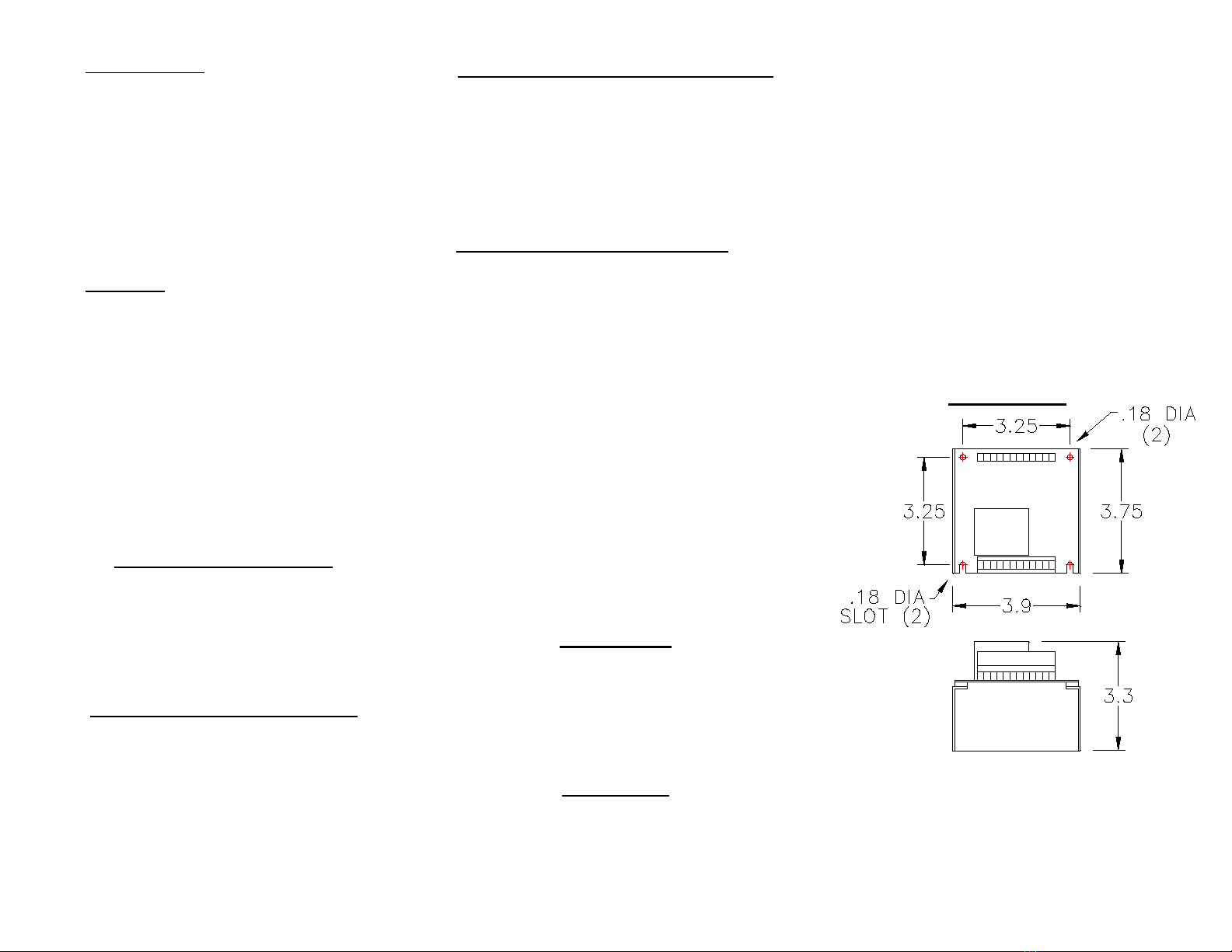
DIMENSIONS
RODIX, INC.
2316 23rd Ave, Rockford, IL 61104
Toll Free (800) 562-1868
E-mail custserv[email protected]
FAX (815) 316-4701
www.rodix.com
FC-44-PLC APP JANUARY 2000
+
FC-40-PLC PLUS
L2VAC:
MAXSOFT
60
-
L1
4-20mA
120
LOAD
(SMALL)
TB1
INPUT
J1
COMMON
AUX FEATURE
G
JUMPER
TB2
TB2
P/N 24-488
TERM. STRIP
-
RUN
S1
CONTROL CARD
HOT
INTERLOCK
+
Transformer
VDC:
Bl #14
Bl #14
WH #14
Vi #20
Or #14
Bl #14
Wh #14
CONTROL
1
-
1/8W MIN
SIG
red
CHASSIS
white
black
SHIELD
J1
MAIN
TIE SHIELD TO
CHASSIS GROUND
AT THE POT END
cw
POT
100K
OPTIONAL
POT
+
GND
TB1
CHASSIS
LINE VOLTAGE
3
12
12
11
8
POWER
HOT
78
11
GND
TRIAC
9
COM
5
4
INPUT POWER
HOT
A2
A1 GATE
1
6
(TALL)
2
TERM. STRIP
10
COM
5 976
10
OUTPUT POWER
RODIX FEEDER CUBE
RODIX INC. ROCKFORD IL 61104-7337
FC-40
Plus Series
Plus SeriesPlus Series
Plus Series
APPLICATION NOTE
OPEN FRAME MODEL
RODIX INC.
FEEDER CUBE


FC-44-PLC
Plus
PlusPlus
Plus
ALL PURPOSE
OPEN FRAME MODEL
IMPORTANT: APPLICATION NOTE
MODEL INPUT VAC AMPS OUTPUT
FC-44-PLC PLUS 120VAC 15A 0-120
1/24/2006 1999-2006 RODIX Inc.



Customer supplied wiring
is shown by dashed lines
7
A)
712
FC-90 PLUS SERIES
AC VOLTAGE INPUT SWITCHING
TERM STRIP TB-2, OUTPUT
5-30 VDC INPUT VOLTAGE
B)
L1
7
J1
OFF/ON CONTROL
8
FC-40 PLUS SERIES TERM STRIP TB-2
12
FEEDER BOWL/HOPPER INTERLOCK
2
11
11
J1
6
L2
8
9
8
12
OFF/ON CONTROL GUIDE
PADDLE
FC-40 PLUS SERIES TERM STRIP TB-2, INPUT
5
1
+
C)
11
8
5
10
FC-40 PLUS SERIES TERM STRIP TB-2
6
105-250 VAC INPUT VOLTAGE
FC-40 PLUS SERIES TERM STRIP TB-2
5
7
D)
10 6
910 6
See section 3 of the Application Note for more
details.
SWITCH
LOW VOLTAGE INPUT SWITCHING
9
9
-
11
OFF/ON CONTROL
3
10
LOW CURRENT
SWITCH
12 5
RODIX SOLUTION
Good wiring practices for
avoiding electrical noise
problems.
Rodix controls have been designed with a
high degree of immunity to electrical
noise; however, depending on the control
installation, electrical noise can cause
problems. These problems occur in less
than 1% of the product installations. Most
electrical noise problems can be avoided
by following some simple guidelines.
Good wiring practices need to be used to
prevent electrical noise from interfering
with your control’s operation. Another
name for electrical noise is Electro-
Magnetic Interference (EMI).
Symptoms of Electrical Noise
The symptoms of electrical noise would
appear as follows: a brief pause or a brief
“bump” in the vibratory feeder’s output
that the control automatically recovers
from. In rare cases the control will either
stop operating or run continuously at full
power in 120 pulse mode until the power
switch is slowly cycled OFF and ON.
Sources of Electrical Noise
Electrical noise is generated by devices
like relay coils, solenoid valves,
contactors, servo motors, and variable
frequency inverter drives. The electrical
noise is then transferred to another
device by one of three ways. The noise
could be conducted through the power
wires, or capacitively coupled from wire to
adjacent wire, or it is transmitted from the
wires of a noise source.
Solutions for Electrical Noise
1. Use shielded wires for all I/O (Input
/ Output) signals. The I/O signals may
include: 4-20mA input, Run input, Sensor
input, 0-5VDC input, Interlock input or
AUX output. The shield “drain” wire
should be tied to the chassis in the Rodix
control. The drain wire should be kept
shorter than 2”. Please see the enclosed
picture.
Example of a “drain” wire termination
2. Never run I/O signal wires in the
same conduit or raceway as AC power
lines such as wires to motors, solenoids,
heaters, welders and Rodix controls, etc.
3. I/O wires within an enclosure
should be routed as far away as possible
from relays, solenoids, transformers,
power wiring and other noisy equipment.
Keep the I/O signal wires separate from
the control’s input and output power
wiring. Secure the wires in place.
4. Whenever relays or solenoid
valves are used, install a Snubber on
them to reduce electrical noise. Use a
diode on a DC coil. Use a RC Snubber
on an AC coil.
5. In extremely high EMI
environments, Power Line Filters and
ferrite beads can be effective. Install
ferrite beads on I/O signal wires as close
as possible to the circuit board terminal
strip. Loop the wire through the bead
several times or use several beads on
each wire for additional protection.
RODIX, INC.
2303 23rd Ave. Rockford, IL 61104
Toll Free (800) 562-1868, FAX (815) 316-4701
E-mail custserv[email protected]
www.rodix.com
2000, 2003 RODIX INC. Solution 408 11/17/03
RODIX INC.
FEEDER CUBE


Plus Series
Plus SeriesPlus Series
Plus Series
RODIX SOLUTION
.408



Drain
Wire
RELAY
COILSNUBBER
VAC
104M06QC47
QUENCH-ARC
RECTIFIER
DIODE RELAY
COIL
1N4006
VDC
+
-

Other manuals for FEEDER CUBE FC-90 Plus Series

3

This manual suits for next models

3

Other Rodix Industrial Equipment manuals

Rodix FC-40 Plus Series Setup guide

Rodix

Rodix FC-40 Plus Series Setup guide

Rodix Autotune Series User manual

Rodix

Rodix Autotune Series User manual

Rodix FC-100-PLC Plus Setup guide

Rodix

Rodix FC-100-PLC Plus Setup guide

Rodix FEEDER CUBE VF-393 User manual

Rodix

Rodix FEEDER CUBE VF-393 User manual

Rodix FC-42-DC Plus User manual

Rodix

Rodix FC-42-DC Plus User manual

Rodix FEEDER CUBE CE-40 Plus Series Setup guide

Rodix

Rodix FEEDER CUBE CE-40 Plus Series Setup guide

Rodix FEEDER CUBE FC-40 Plus Series Setup guide

Rodix

Rodix FEEDER CUBE FC-40 Plus Series Setup guide

Rodix FEEDER CUBE VF-3-2 User manual

Rodix

Rodix FEEDER CUBE VF-3-2 User manual

Rodix FEEDER CUBE FC-40 Plus Series Setup guide

Rodix

Rodix FEEDER CUBE FC-40 Plus Series Setup guide

Rodix FEEDER CUBE FC-40 Plus Series Setup guide

Rodix

Rodix FEEDER CUBE FC-40 Plus Series Setup guide

Rodix FEEDER CUBE FC-41-480 Series Setup guide

Rodix

Rodix FEEDER CUBE FC-41-480 Series Setup guide

Rodix FEEDER CUBE VF-18 User manual

Rodix

Rodix FEEDER CUBE VF-18 User manual

Rodix FEEDER CUBE FC-100 Plus Series Setup guide

Rodix

Rodix FEEDER CUBE FC-100 Plus Series Setup guide

Rodix FC-40 Plus Series User manual

Rodix

Rodix FC-40 Plus Series User manual

Rodix FEEDER CUBE VF-3-3 User manual

Rodix

Rodix FEEDER CUBE VF-3-3 User manual

Rodix FEEDER CUBE FC-40 Plus Series Setup guide

Rodix

Rodix FEEDER CUBE FC-40 Plus Series Setup guide

Rodix FEEDER CUBE FC-40 Plus Series Setup guide

Rodix

Rodix FEEDER CUBE FC-40 Plus Series Setup guide

Rodix FEEDER CUBE VF-9-2 User manual

Rodix

Rodix FEEDER CUBE VF-9-2 User manual

Rodix FEEDER CUBE FC-40 Plus Series Setup guide

Rodix

Rodix FEEDER CUBE FC-40 Plus Series Setup guide

Rodix FEEDER CUBE VF-12 User manual

Rodix

Rodix FEEDER CUBE VF-12 User manual

Rodix FEEDER CUBE VF-9-3 User manual

Rodix

Rodix FEEDER CUBE VF-9-3 User manual

Rodix FEEDER CUBE VF-9 User manual

Rodix

Rodix FEEDER CUBE VF-9 User manual

Rodix FEEDER CUBE FC-40 Plus Series Setup guide

Rodix

Rodix FEEDER CUBE FC-40 Plus Series Setup guide

Rodix FEEDER CUBE FC-70 Series Setup guide

Rodix

Rodix FEEDER CUBE FC-70 Series Setup guide

Popular Industrial Equipment manuals by other brands

Lavorwash SPRAY NV24 manual

Lavorwash

Lavorwash SPRAY NV24 manual

SnowEx Brine PRO 2000 manual

SnowEx

SnowEx Brine PRO 2000 manual

Tetra Pak COMET RC manual

Tetra Pak

Tetra Pak COMET RC manual

Premier 240 COUPLING Installation, Inspection, Operation & Maintenance Guide

Premier

Premier 240 COUPLING Installation, Inspection, Operation & Maintenance Guide

hager UZ1LA2 Series Mounting instructions

hager

hager UZ1LA2 Series Mounting instructions

RIDGID 141 Operator's manual

RIDGID

RIDGID 141 Operator's manual

Aerotech ACS LP Series Hardware manual

Aerotech

Aerotech ACS LP Series Hardware manual

ABB TPS48-H32 Operation manual

ABB

ABB TPS48-H32 Operation manual

Trak Machine Tools TMC5 manual

Trak Machine Tools

Trak Machine Tools TMC5 manual

Nakanishi AL-A1205 Operation manual

Nakanishi

Nakanishi AL-A1205 Operation manual

BLUM MINIPRESS Safety instructions, set-up instructions and instruction leaflet

BLUM

BLUM MINIPRESS Safety instructions, set-up instructions and instruction leaflet

Pitzl 10529.1093 quick start guide

Pitzl

Pitzl 10529.1093 quick start guide

Siemens SIMATIC IPC operating manual

Siemens

Siemens SIMATIC IPC operating manual

PCB Piezotronics 1631-06C Installation and operating manual

PCB Piezotronics

PCB Piezotronics 1631-06C Installation and operating manual

Eastey EA Professional Series user guide

Eastey

Eastey EA Professional Series user guide

Metso Nordtrack J90 DRIVING INSTRUCTION

Metso

Metso Nordtrack J90 DRIVING INSTRUCTION

Panblast BB120S-2 CORSA II Owner’s Operation and Safety Manual

Panblast

Panblast BB120S-2 CORSA II Owner’s Operation and Safety Manual

Pinnacle Aquatic Hyprolyser 560 user guide

Pinnacle Aquatic

Pinnacle Aquatic Hyprolyser 560 user guide

manuals.online logo
manuals.online logoBrands
  • About & Mission
  • Contact us
  • Privacy Policy
  • Terms and Conditions

Copyright 2025 Manuals.Online. All Rights Reserved.